| Index About Me |
Computer-Controlled Machining AssignmentThe indications for this assginment were simple and practical: make something big.After the class session, I spent quite a while going over different ideas of something to make, I stopped writing when I surpassed twenty-five. In the end, the decision came from meeting wishes with actual reality: The lab needed some furniture and, since the best idea I could come up with was a dopamine-molecule-like coffe table, which included a central table (The Benzene ring) and some arms with spaces with glasses or other stuff. I scribbled kind of a sketch over this molecular diagram, in red the platforms (or receptacles) and in green the main table.  BitsBeing aware of the conditions and rectrictions, and after the experience acquired in previous lessons, I started designing in Inventor: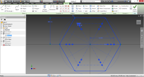 I started with a
hexgonal piece for the table top, and in doing this, I dedcided that I
needed something unconventional about the support, I was thinkning of
using supports parallel to the hexagon sides, which would have sufficed
as coffee table, but not for a taller table, so I decided to make holes
in the top piece in different radial directions in order to press-fit
the suports below.
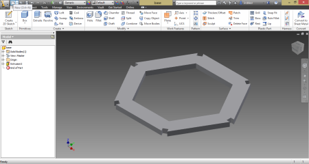
I was not very clear about how to make the fittings independent from the material thickness, so I decided to make simple fittings, relying on the material thickness and making them parametric, building on the lessons learned from the second assignment. Thus, I came out with a top piece and six legs (three would have done the job) I went on for six in order to increase stability 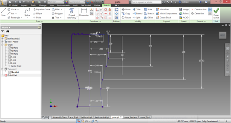 I finished
designing both parts and simulated the assembly in inventor, the
software lets you simulate where will the center of gravity of the
assembly be, which can be seen in the image below.
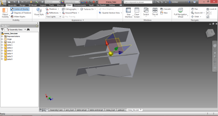 In order to lower the center of gravity, I dediced to add another piece to the assembly in the lower part in order to lower the center of gravity and secure the legs in the lower part. As the original geometry was an hexagon, I made an hexagonal profile, created the fittings in the 2D drawing and extruded it with inventor.
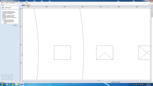
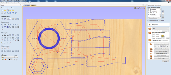
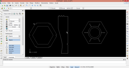 As soon as the exported DXF files were opened in Partworks, I realized some adjustments had to be made, first, as it had already ocurred in the laser cutting assignment, the exported drawings had disjointed and duplicated lines, which I had to take care of in Partworks, joining lines and curves in closed trajectories and deleating repeating lines:
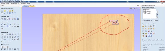
Roberto suggested I
should make a test cut to check if the fittings were good, the lines
not being welded properly was useful for this. The test cut is marked
in red. I made three parts, one for the legs' fittings(or claws)
another, with the holes for the table top and the third and smaller one
for the hexagonal profile piece.
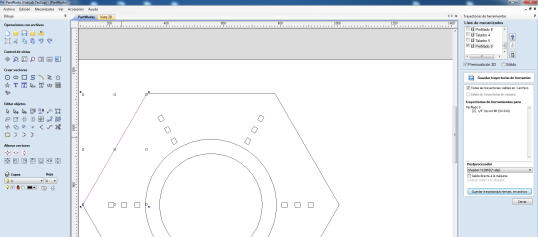
After testing, I placed the pieces in the partworks sheet, here I made a mistake regarding the canvas height, I worked and placed the pieces using a measurement greater than the actual height of the workpiece. This would cost me in the machining phase.
After placing the pieces, I proceeded to generate the toolpaths for the milling machine as they can be seen in the image below. I used small drillings for placing the screws and profile cutting in order to obtain the legs and table top, I made the profile cutting in four tool passes, with a total height of 16mm (4mm each) at a 18000 rpm speed. Additionally, I added a pocket milling toolpath in the region between the circles that can be seen in the picture above. The same 1/4' straight cut mill was used for all the toolpaths.
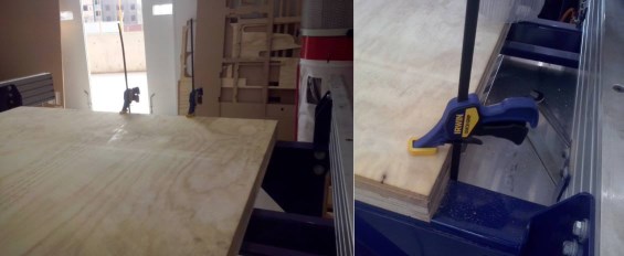
AtomsThe following section of the report is about, esentially, the machining process, the first thing to do was to select the material for machining, following a suggestion by Roberto I chose a 15.6 mm Plywood for milling. After selecting it, the next step was to place it in the machining bed. But first, cleaning: 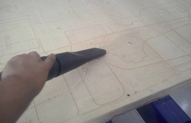 The second thing to do was fixating the plywoood to the machine, which I did using screws and clipping pressed, this because the piece was bent, ultimately, this fact would be determinant.
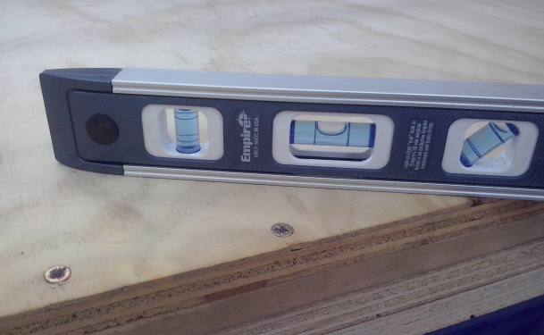
As the plywoood was
place and y drilled the screws to fixate it, I realized it was still
bent and more screws would be needed in order to keep the sheet
leveled. I added three more in different places of the sheet, after
doing this, I checked if the platform was leveled:
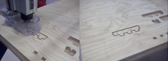
After this, It was time to start machining, as already written: It was first milling the test pieces:
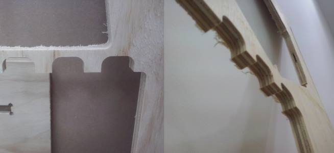
the first attempt was not succesful, so I added "Rabit ears" to the holes and made them a little wider in the design, accordingly, I milled a new piece in order to test this new set of holes and... It fits!
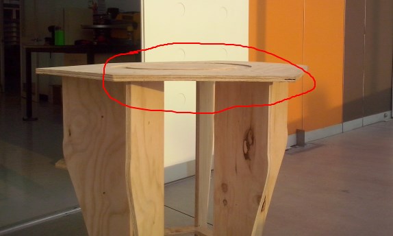
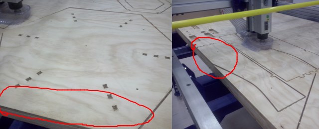
Then, it was time to machine the whole set, but first, I had to place the screws in the table, afterwards, machining: 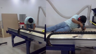 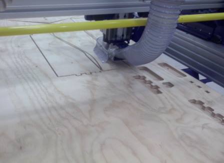 As the miller was
progressing, the mistake I made regarding the canvas height became
evident, as one of the legs was not completely cut ( a short part was
not really milled, since there was nothing there) and the table top
(which lost a few millimeters for the same reason) in the image below,
they are marked in red:
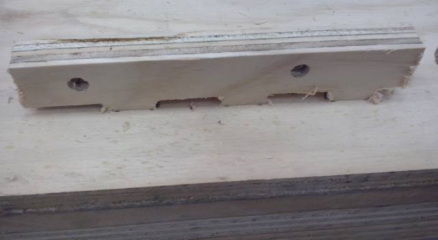
 The first thing I noticed after unscrewing the pieces, was that there was a certain amount of plywood fiber left in the cut pieces, and particularly, in the holes drilled:
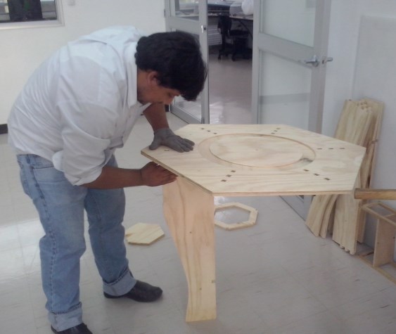
The assembly was not very complicated, but the pieces required a moderate amount of sanding before assembling, specially, the holes. Then it was time to putting the legs together with the tabletop:
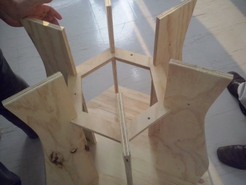
The workflow was simple: inserting the "claws" of the legs into the holes of the tabletop and then, using the rubber mallet to get them firmly togehter, Yabed helped me with that. Then, as the final piece of the base was added, I realized of another mistake:
The Base piece would not fit in all the six legs holes, in the photo, it looks good enough, but it is not tightly fit into the structure, so, in the current state of things, is kind of useless. I need to cut a bigger piece to compensate. Also, We found out that the table was not fully leveled, Why? The plywood is to blame for this, it seems it was bent all along, a slightly longer leg would be needed to compensate for this:
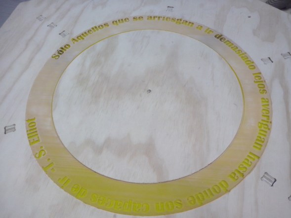
As a final detail, I laser cut an acryllic glass piece in the laser cutter to fill the pocket cut. The fit was not perfect and needed some extra sanding and cutting, still not completely finished:
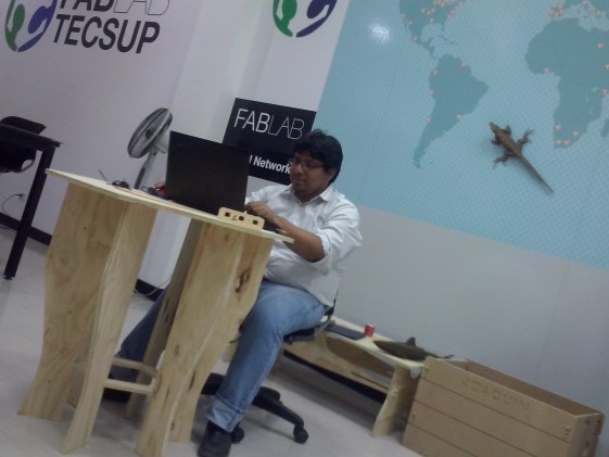
After this, it was time to make some test driving, so I put my laptop on top of it and started working, the space is comfortable, not completely ergonomic, and two people can work in the table just fine, three a little crowded.
The Inventor parts and assembly for this project can be found Here. Conclusions?First, be mindful about the materials you use, Plywood tends to bend, MDF not, and so on... Second, check ALL parts of the machining bed are leveled Third, test your assemblies BEFORE actually cutting the piece Fourth, sanding is essential. Fifth, be patient (I think this one is the most important) |