| Index About Me |
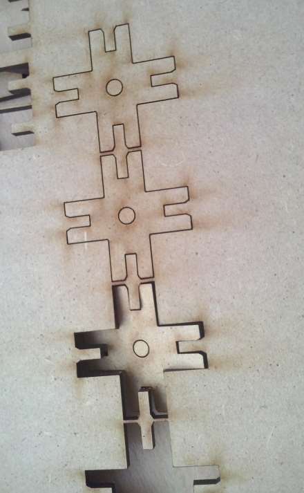
Computed Controlled Cutting AssignmentThe Challenge for this assignment was two-fold: first, using the Vynil Cutter and second, making a press-fit kit, which I chose to make using the laser cutter.Vynil CuttingI decided to go as simple as possible with the Vynil cutter, and since I needed some decorations for my laptop, I readied a couple images for cutting using the fab modules app, The process was quite easy and simple to get through. 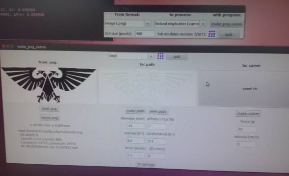 The tricky part came when It was time to take it out of the Vynil and paste it into the laptop. First mistake: I sent another image to the plotter without actually verifying the position for the blade, meaning I actually had to re-cut the eagle, not so good-work. 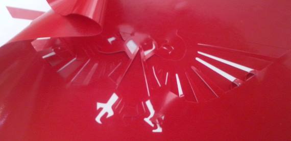 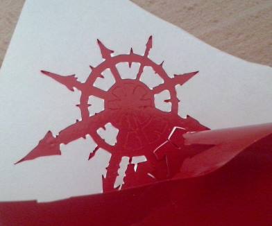 The second mistake I made was actually not being patient enough when the time came to paste the objects into the laptop. Why? The parts (being more specific, the eagle) were quite small,and some details (like the head and beak) did not bonded properly to the surface, so, when I removed the transfer tape, the results were not optimal. the second figure was not so complicated, so it was simpler to get it pasted. Finally, here are both figures in place, the one of the eagle´s heads and one of the claws are gone by now. 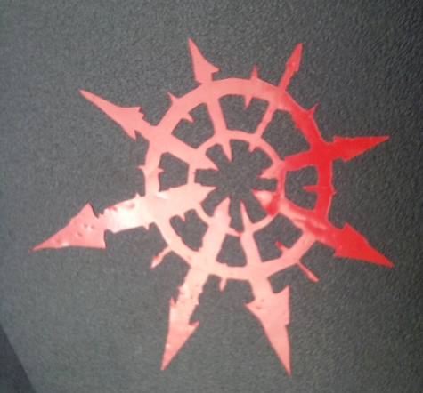 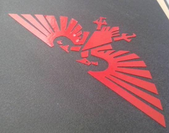 Laser CuttingThe real challenge, on the way to getting a press-fit kit done, was how to design the kit in order to take into account the thickness for various materials. The first idea I had was to make a press-fit molecule kit, so simple molecules could be represented (for instance, Hydrocarbons) I was aiming to make a methane-like structure, or some other simple Hydrocarbons 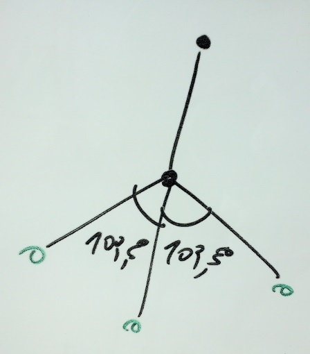 Afterwards, I
started designing, but
as I was going on tinkering with CAD software I started to work on how
to make the designs parametric.
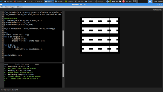
Since the simplest way of getting parametric was setting the model geometry as a function of a given variable (the parameter) I picked up where I left off in the last assignment and started coding in OpenSCAD: 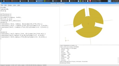 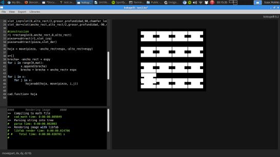 After reading,
re-reading, and testing the script, I got to make it work just fine
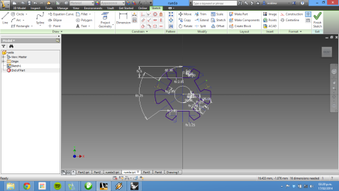
 Next on my list was using grasshopper to see how different is was to produce parametric forms for cutting. But I could not make it work, so, after some researching, I went to Inventor.
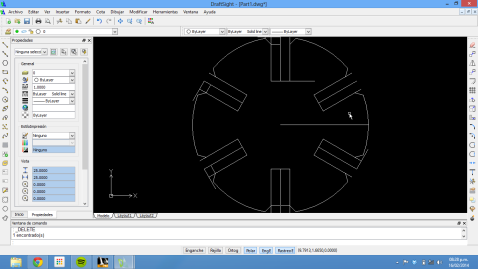
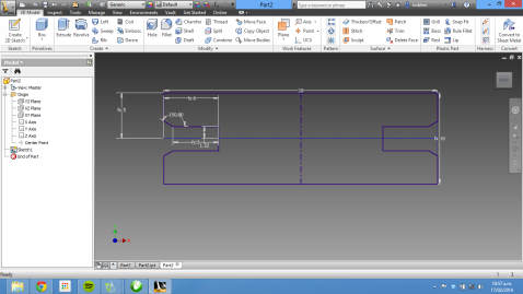 However, designing with Inventor forced my to add an additional step to the workflow, given that Inventor will not export its sketches to DXF for laser cutting, I had to save them as DWG (AutoCAD format) and then open them for export using Draftsight:
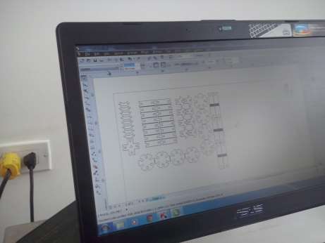
This added up to the workload, since the exporting process sent all the lines in the same layer, regardless of them being drawing or construction lines. A line-clean up was in place, and it had to be done anyway since it is necessary to check for double lines or ghost lines before actually cutting. After this being done, I exported the files to Corel Draw for cutting:
Cutting was actually the easiest and quickest part of the assignment. 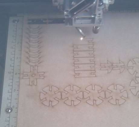
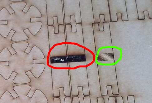
First, in the model I drew a set of lines in the middle of one piece in order to make it flexible, the lines were too tightly drawn, and the MDF burnt, I corrected by removing most of the lines, but to no avail, the piece was just as rigid, A bigger model with more lines would be more suitable. The second mistake was the scale, the pieces were too small to be fully useful.
Third, some slots
were just too wide to make a good match, so the couplings were, at some
cases, too loose.
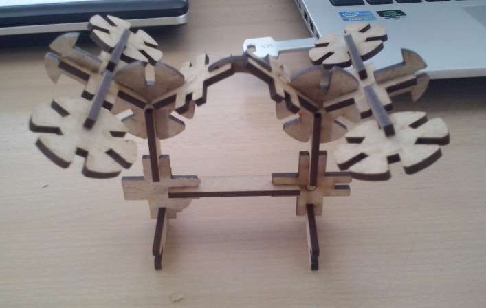
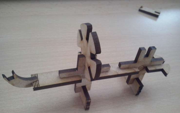
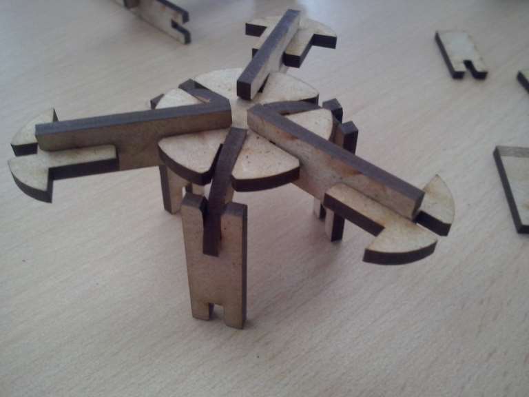
As I was starting to assemble, I realized that in order to make the assemblies stand I needed a different kind of piece to make this happen, farewell hydrocarbon models. There is a lot of room for improvement. Below are some photos of shapes I made tinkering with the kit: |