| Index About Me |
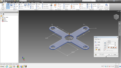
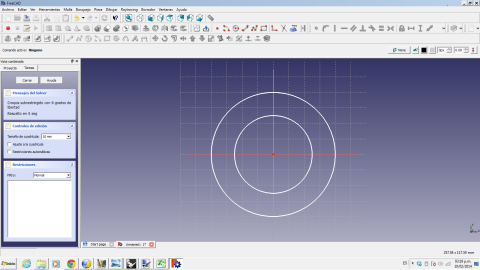
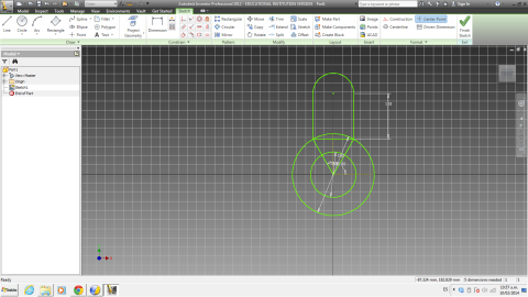
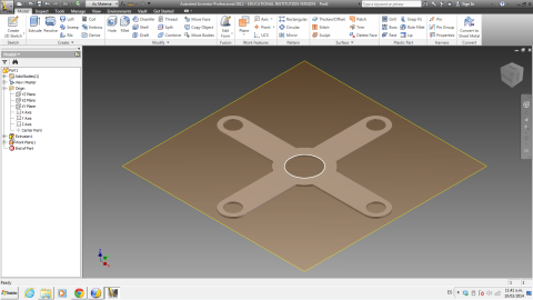
Computed Aided Design AssignmentFor this assignment I decided it was necessary to wortk through different tools to compare and work through, taking into consideration that the short amount of time given would not let me go fully through the learning curve of every software chosen, so, ultimately it was about which sotwrare could get the job done in the most comforable and straightforward manner.During the last week I tried to work with several Software Tools including: Autodesk Inventor and Fusion 360, Rhinoceros, OpenSCAD and FreeCAD. Of all of the mentioned above, I found Inventor the most useful, mostly because of some previous experience I had with it and because of the how the software emphasizes model dimensioning over geometry drawing, which is, in my opinions, one of the reasons why Rhinoceros was not so appealing to me. First, I thought of the simplest possible design for my project, which you can see in sketch below: 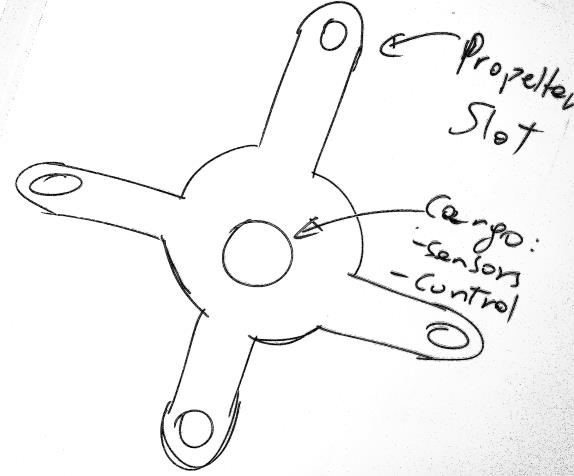 A different option would need to be chosen in the case of making a Hexacopter, since its complexity would not make it possible to cut it in a single piece and an assembly process would be recomended, I will return to the hexacopter issue in a further update. Having already decided on the shape, it was time to work on the software. I started with inventor. The interface was pretty friendly and the model geometry work was quite straightforward, using simple geometric features and symmetry to get the model done 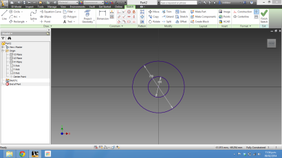 Creating the model
implied drawing the "arms" of the copter and the slots indicated in the
sketch above, it had to start with at least one of them, based upon the
geometry of the circles. One of the important features of Inventor is
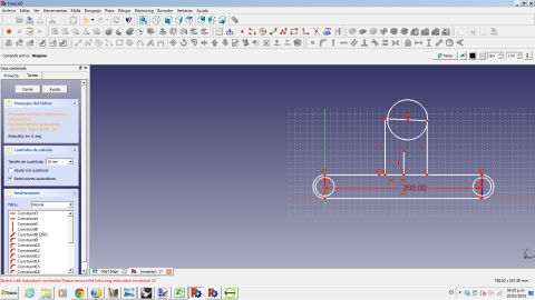
the importance of constrains in geometry, which can be seen in the
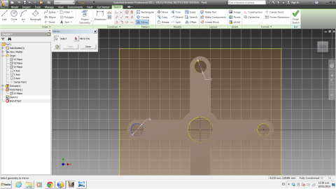
screen as blue lines (when it's ok) and in green (see picture below)
when some measurements or constraints are not ready. It is important to
be mindful about the constraints before making transformations such as
mirroring and rotating a section of the sketch, since this can alter
the constrained geometry and create inaccurate measurments.
 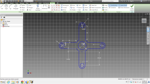 After finishing
the 2D sketch, you can see the drawing in an isometric view::
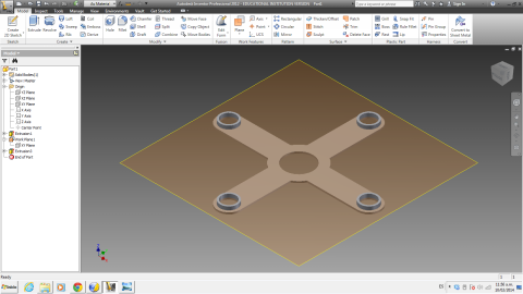
 From there, I extruded the profile to a 3mm height, since acryllic can be found of such height.
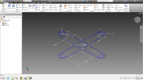
 From here, drawing the circles for the additional pieces was quite simple.
And, after a few transformations, and another extusion, I had the additions ready: 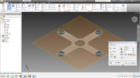
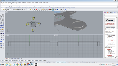
When I switched to Rhino, the main difference I could find was that it does not really enforce a definite geometry or adscribes it to certain measurments. In 2D the drawing is pretty straightforward but since there are not first-hand drawing aids like inventor, you need to be mindful about the measurments and geometry. The main incident I had with this was when I made the extrusion from 2D to 3D, I did not take into account the effects derived from grouping the curves in two different sets, one the center hole and the "cross" section, and another for the holes in the sides.
This forced me to use another command to create the holes, instead of getting it all round up in a single extrusion, but finally, it was done: 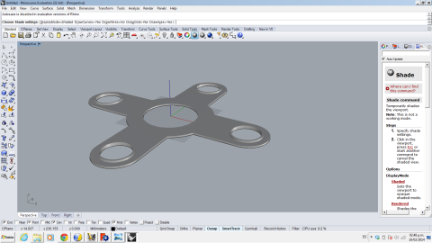 Attempting to get some work done with FreeCAD turned out to be a lot more challenging that expected, due to the lack of usability features in the program (for instance, you need to locate very precisely the location of a given point in order to draw a figure) and 2D transformations (such as mirroring) made it very hard to use, it's just not there. So after more than an hour of trial and error, I left it. Just a couple things: in the first photo you cannot know if both circles are really concentrical . And in the second, the difficulties arising from trying to work with the sketch are shown, there are not enoguh features to get the work done without incidents.
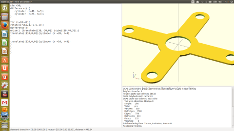
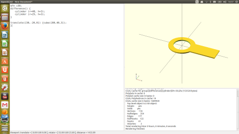
Finally, I decided to give openSCAD a try, since the coding syntax seemed somewhat familiar, a remarkable difference compared to the other applications used is the design approach, since you can work directly with 3D forms without any need for 2D modelling, this is a photo of the final model:
However, just like everything related to coding, it is necessary to plan ahead a development strategy for your geometry, in my particular case, I decided to start from the central cylinders and work the "arms" afterwards. 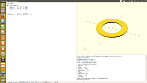 After watching a
few online videos and reading a few more. I was able
to produce the intended geometry with some lines of code, it may not
be the optimal way, but certainly gets the job done.
It is still pending the animation/simulation part of the assignment, which will be dealt with in a further update. |