| Index About Me |
Machine Design AssignmentThis assignment was a hands-on approach to making a MTM machine  In this case, the instructors chose to make a MTM Snap mini- Milling machine. We worked in the assembly of the mehanical and structural parts, but not the Electronics/control. The MTM Snap is a 3-axis smal milling machine, before talking about the assembly, I'll mention a few details about the machine.
 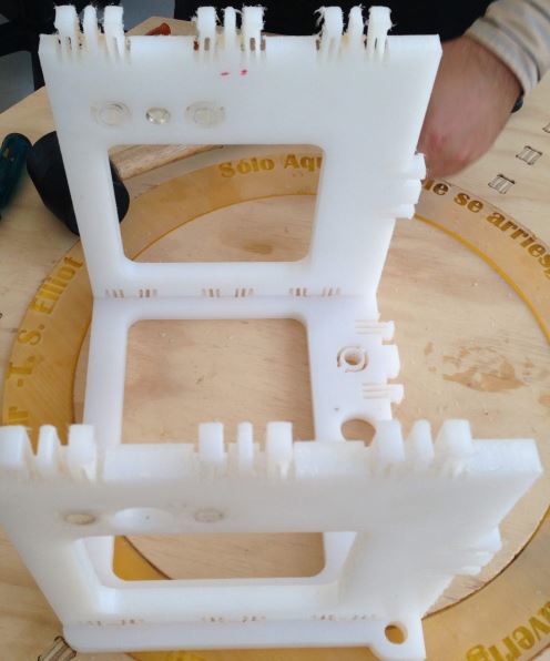
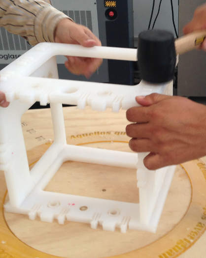
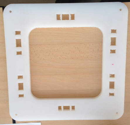
The first piece to
start the asembly is the side frame. The holes designed for the snap
press-fit can be seen in this image.
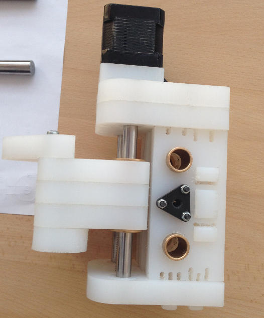
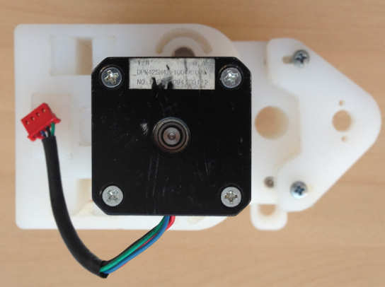
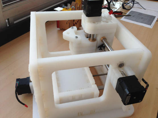
The Z- axis movement, which will determin the height of the mill is governed by the montage below, as it can be seen, the stepper motor uses a threaded rod to move the assembly on the Z-axis, in this image the assembly for the X- axis can be sen on the side, the spacers for the reference shafts and the center piece for the threaded rod, still not fully assembled..
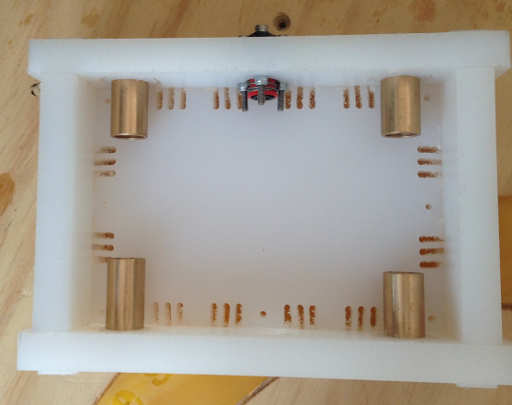
The Y-axis array is moved through a similar mechanism as the Z and X-axis, only in this case, the container is the moving table for the stock material to be milled, so the moving array is essentially moving a box in the axis.
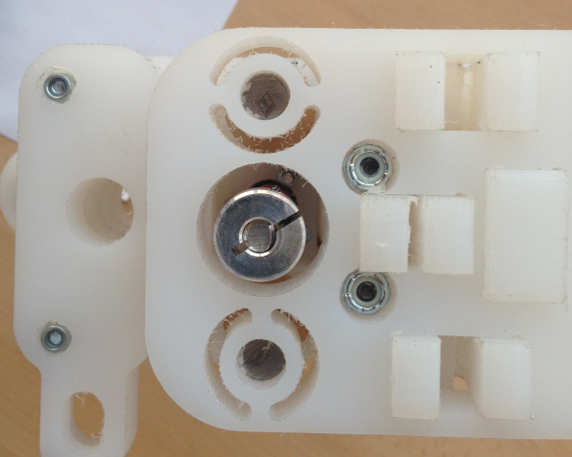
Below a detail of the endmill assembly can be ssen, the shafts and the coupling for the threaded rod.
This is a detail view of the Z-axis array.
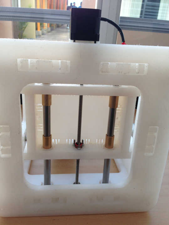
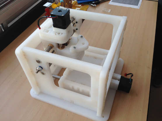
As the assembly progressed, more and more details of the integration can be seen, the image below, the Y-axis array integrated to the framing, the moving table can be seen too.
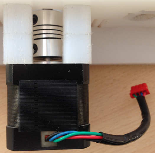
To make a machine of this kind, the usage of elements such as bearings, nuts, bolts, washers and couplings is mandatory, here can be seen a helical coupling attached to the stepper motor.
After some hours of work, the final design could be seen:
From another angle, the machine assembled:
Conclusions?It is necessary to know about the mechanical elements before assembling the machine. Even though the work was very thorough, more is needed in order to really understand the details Third, making a machine requires careful planning and testing, well established tolerance margins are needed. |