Output Devices
Task:
add an output device to a microcontroller board you've designed and program it to do something.
Description:
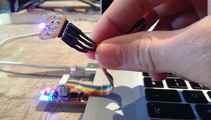
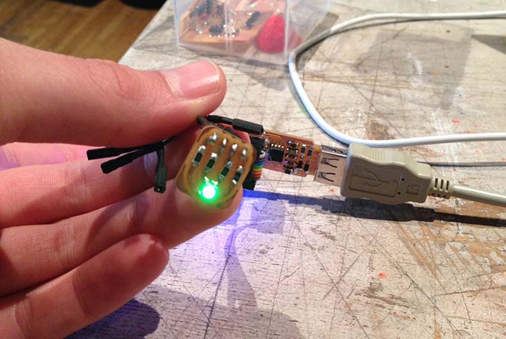
For this assignment I created something that could be used for my final project. I programmed my FabtinyStar with an edited version of the DigiBlink code. This is a code used to give an input to an RGB led. Next things I want to do is designing the board in a more suitable way so I can save a lot of space.
What did I do:
- Electronics production
- Installed libraries on my laptop
- Program the board
- Using the DigiBlink script
Electronics production:
This we all did before I milled out another FabTinyStar, this because due to the lack of time to design my own board. I want to do this when I find the time for it. I also milled out a break out board for the RGB led. You can see the process of this at my electronics production page. You can also find the files of the break out board underneath this page.
Installed libraries on my laptop:
For using the DigiBlink python I needed to install different libraries to my computer such as: LibUSB, Python3, PyUSB and webcolors. LibUSB and Python3 are very easy to install through Homebrew. I would recommend anyone with a mac to work through Homebrew it makes live more easy. For libusb just simply input brew install libusb in your terminal if you don't have permission make it sudo brew install libusb for python simpely make it brew install python
The other scripts you should download (bottom of the page) and browse to their directories inside the terminal after this run python setup.py install
Program the board:
For the programming of the board I used the DigisparkArduino environment to program the board. Under examples > DigisparkUSB you can find the DigiBlink code. I adjusted the code a little, this because they used a common cathode and my RGB led uses a common anode.
My code:
#define USB_CFG_DEVICE_NAME     'D','i','g','i','B','l','i','n','k'
#define USB_CFG_DEVICE_NAME_LEN 9
#include <DigiUSB.h>
byte in = 0;
int Blue = 0;
int Red = 0;
int Green = 0;

int next = 0;

void setup() {
    DigiUSB.begin();
    pinMode(0,OUTPUT);
    pinMode(1,OUTPUT);
    pinMode(2,OUTPUT);
}
void loop() {
  setBlue();
      DigiUSB.refresh();
      setBlue();
     if (DigiUSB.available() > 0) {
       in = 0;

       in = DigiUSB.read();
       if (next == 0){
         if(in == 115){
           next = 1;
           DigiUSB.println("Start");
         }
       }
       else if (next == 1){
            Red = in;
            DigiUSB.print("Red ");
            DigiUSB.println(in,DEC);
            next = 2;
       }
       else if (next == 2){
            Green = in;
            DigiUSB.print("Green ");
            DigiUSB.println(in,DEC);
            next = 3;
       }
       else if (next == 3){
            Blue = in;
            DigiUSB.print("Blue ");
            DigiUSB.println(in,DEC);
            next = 0;
       }
     }
    analogWrite(0,255-Red);
    analogWrite(1,255-Green);
     setBlue();
}
void setBlue(){
    if(Blue == 0){
      digitalWrite(2,HIGH);
      return;
    }
    else if(Blue == 255){
      digitalWrite(2,LOW);
      return;
    }
    // On period
    for (int x=0;x < Blue;x++){
    digitalWrite(2,LOW);
    }

    // Off period

    for(int x=0;x < (255-Blue);x++){
    digitalWrite(2,HIGH);
    }

}
Assignment images:
Next steps:
- Design a more suitable(smaller) board.
- Design a cover for the board.
Conclusion:
You really need to be secure with installing the libraries. I installed one without permission and this is why I couldn't figure out at first why the DigiBlink was not working.