Input Devices
Task:
measure something: add a sensor to a microcontroller board that you've designed and read it
Description:
I decided to try out the step response input device for this assignment, this because of the endless possibilities of this input device. I started with designing a circuit board with a ATTINY44 so I would have more analog inputs than the ATTINY45.
What did I do:
- Design a circuit board
- Mill the circuit board
- Create a touchpad
- Read out the board
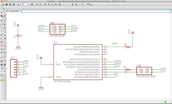
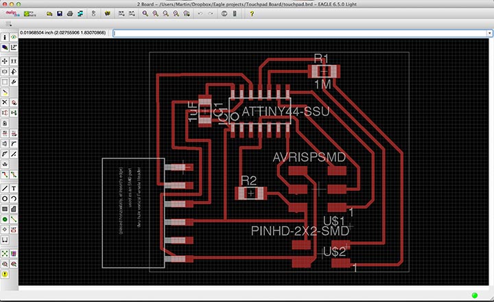
Design a circuit board: (image.1 & image.2)
I used Eagle again to design the board and I added the components. However, first I took some wrong pin headers, instead of using the SMD 2x3 header I used the 6pin through-hole header. The same for the 4pins header so I needed to change this after placing the right components I designed the board layout.
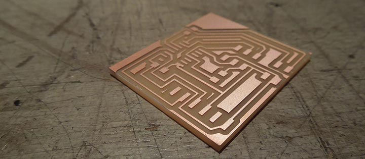
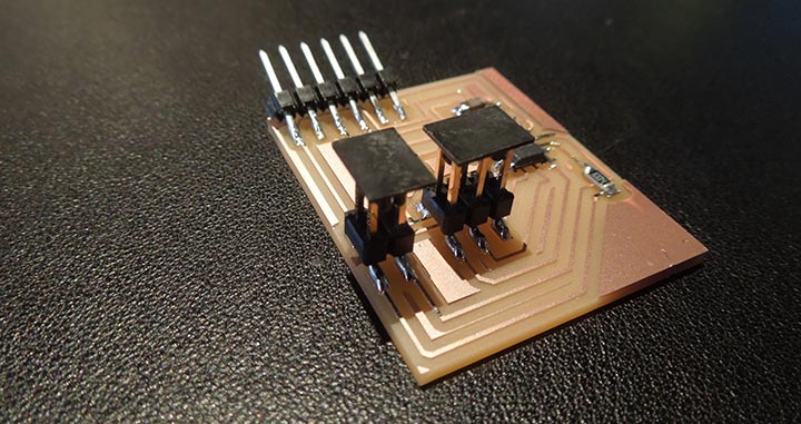
Creating the circuit board: (image.3 & image.4)
After designing the circuit board I was almost good to go for the milling process. This process is familiar to me and again I used the 1/64 for the traces and the 1/32 milling bit for the cutting out of the board. Following the milling process I soldered the components on the board and proud to say I was able to solder the ATTINY44 in the right position the first try :-).
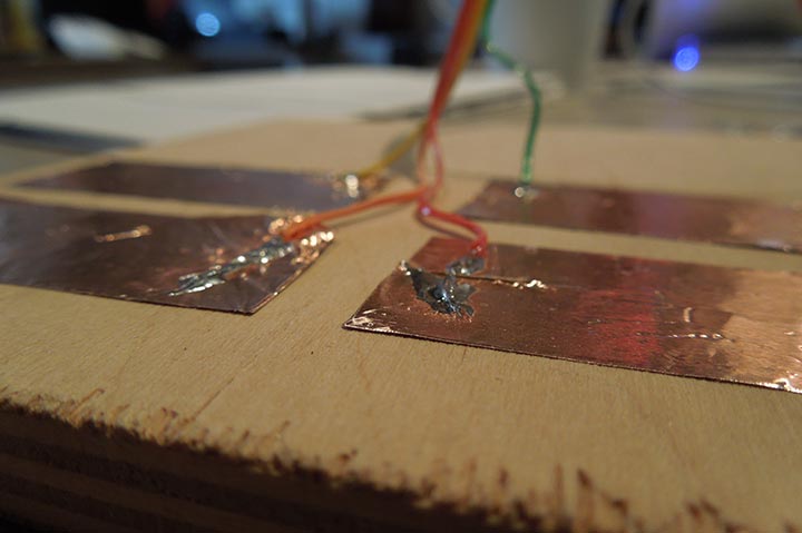
Create a touchpad:(image.5)
For the touchpad I took a piece of triplex and put 4 pieces of copper foil onto it. Then,I connected the 4 cables from the 4pin connector and I soldered to this copper foil.
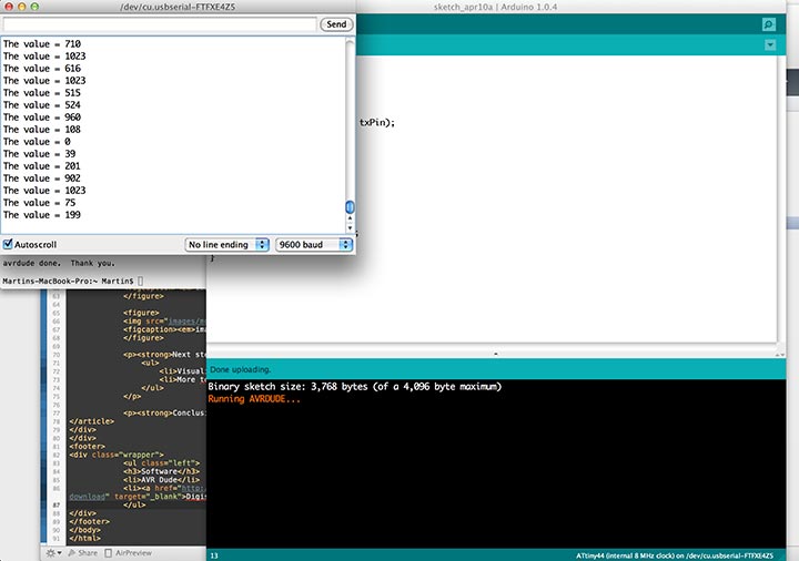
Read out the board:(image.6)
For reading out the touchpad pin, I used the Software Serial library. With this library you can connect your circuitboard to you computer and read it out inside the Arduino IDE. You can find some more information about the library here.
My arduino code:
#include
#define rxPin 0
#define txPin 1
int sw_pin = 2;

SoftwareSerial serial(rxPin, txPin);

void setup() {
serial.begin(9600);
}

void loop(){
delay(600);
int  a = analogRead(sw_pin);
serial.print("The value = ");
serial.println(a);
}
Assignment images:
Next steps:
- Visualise the read out
- More touchpads
Findings:
It's handy to add a ground to your touchpad, this because the values stay much more stable than when the ground needs to go through the literal ground.
Conclusion:
I'm getting more comfortable with designing and programming a circuit board. At first, the input device was quite a blur for me but after an awesome explanation by my fellow student Emma I started to understand the touch response.