ASSIGNMENT
Redraw the echo hello-world board, add (at least) a button and LED (with current-limiting resistor)
check the design rules, and make it. extra credit: simulate its operationBuild our own web-site.
LAYOUT PCB
I dowloaded the schematic of the hello-word board from this tutorial. I already had some expirience with eagle and PCB layout and I decided to try a double-side mill.
This is the my hello-word board schematic:
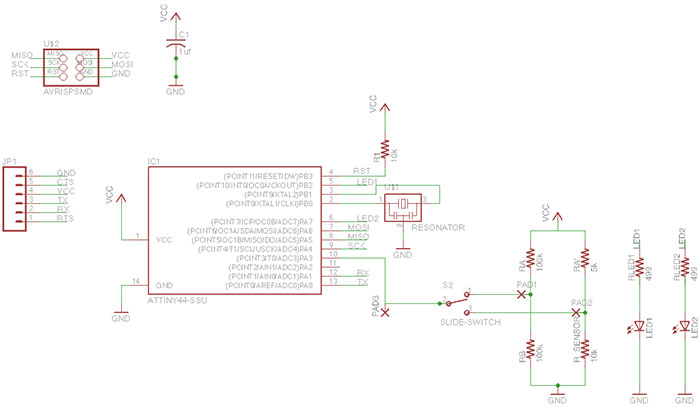
I added:
- 1 blue LED and 1 RED LED
- 2 resistors (499 Ohm), to limite the current over the LED
- 2 resistors (100k), to create a resistor divider
- 1 vibration sensor (sensore-micro-vibration)
- 1 resistor (5k), to limite the current over the sensor
- a slide switch, to select olny one input for the microcontroller.
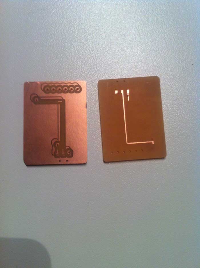
The board layout is:
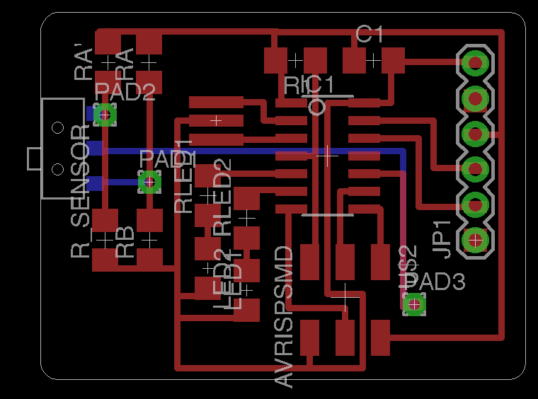
The red lines are the copper line on the top, the blue line are milled on the bottom and the green pad are called VIA and are the holes I will use to connect the top and the bottom side. I generated my .png image directly from eagle: File -> Export -> Image and selected the option: Monochrome, dpi 1000. My three png files were ready:
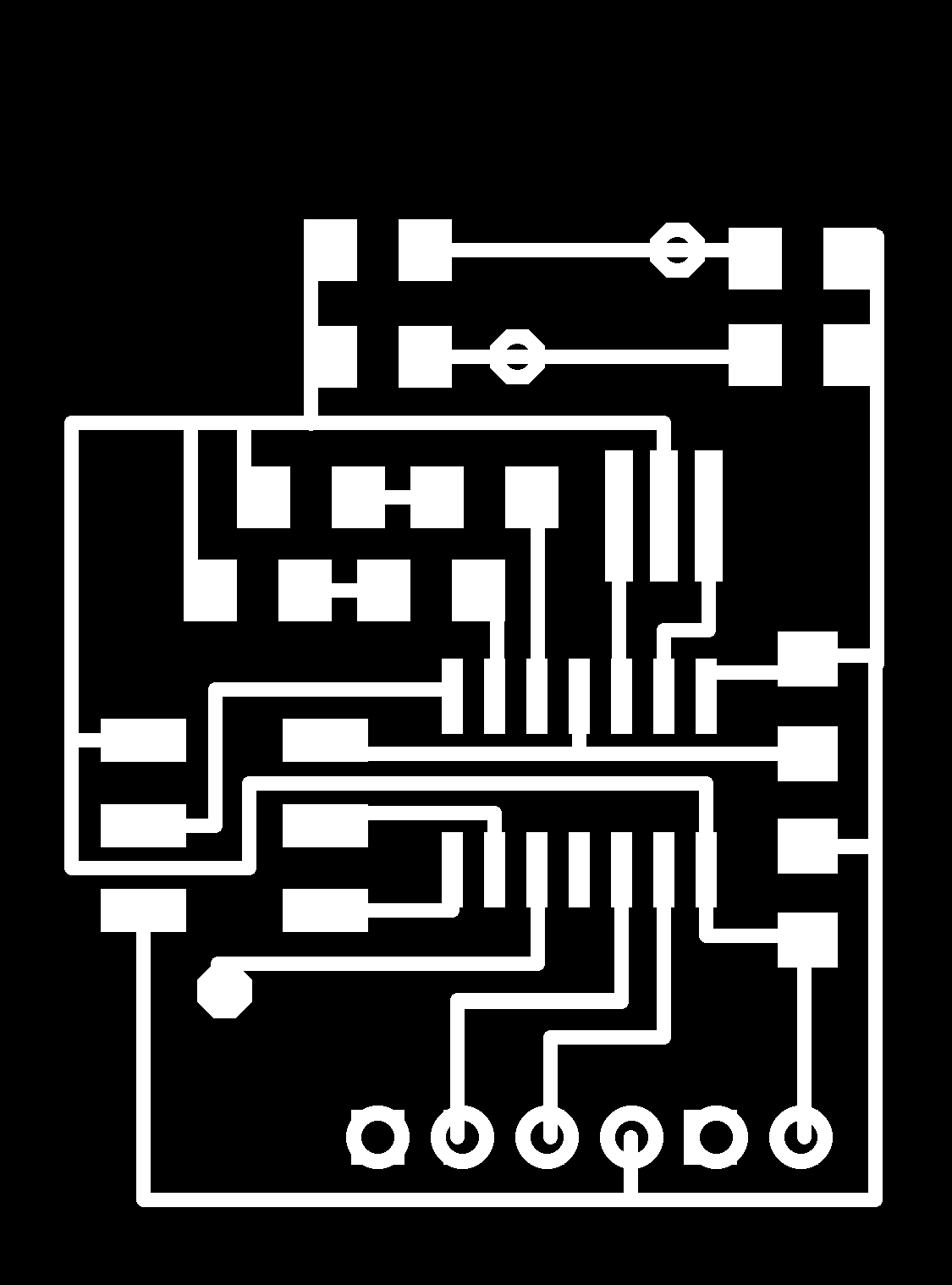
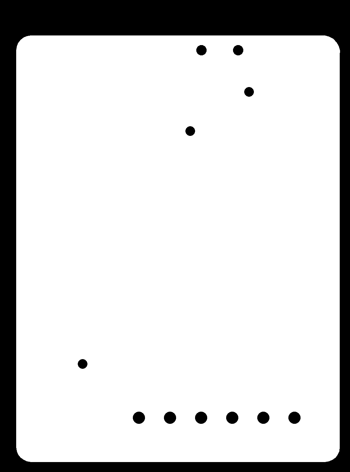
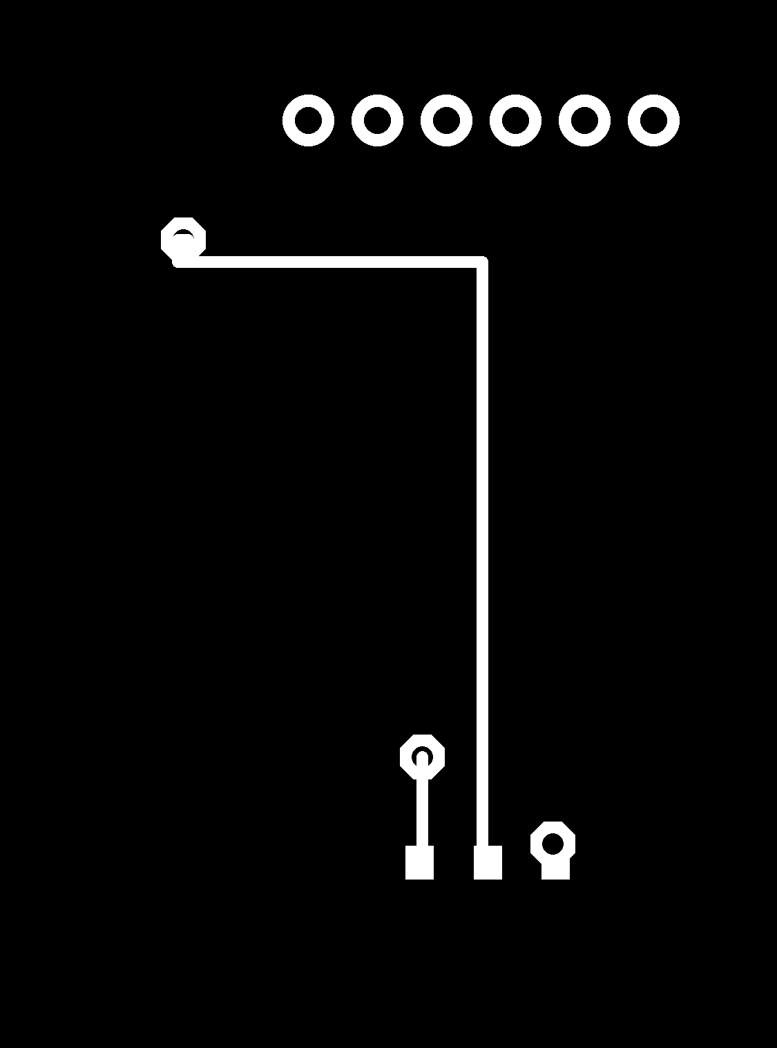
The middle one (that I used to drill and cut the board) has been modified with GIMP: Tools -> Paint tools -> Bucket fill (white-black). The bottom one has been horizontally reflected because I fliped my board on the same direction. I milled and cutted like in class 04. I turned the cutted board and fliped horizontaly. To have a reference between the two sides I smoothed the left-low corner and fit the board in the hole. I changed the set-up of the bottom milling job: I moved the origin to compensate the clearence on two sides,if your layout is simmetric I suggest to try changing the origin of the drill bit diameter, for me -0.8 mm (but I had to find my right shift because my layout wasn't simmetric, care!).
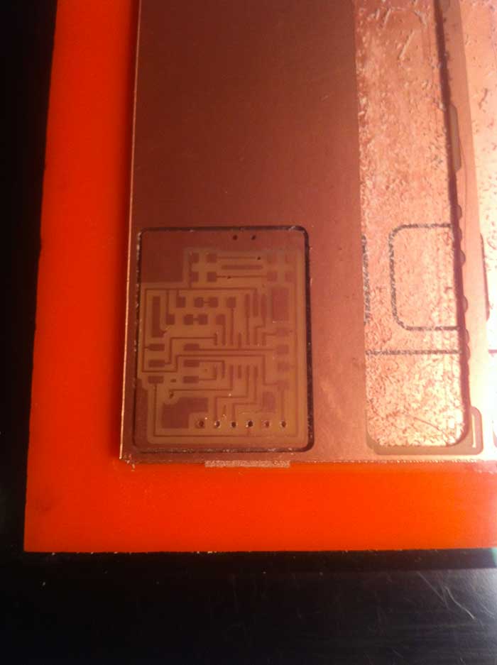
My third attempt was the right one and I forgot to take a picture before to solder so I can show you the wrongs:
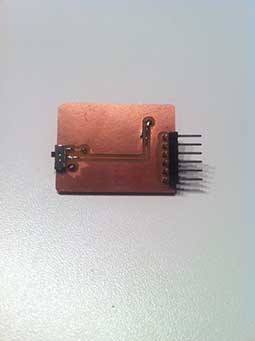
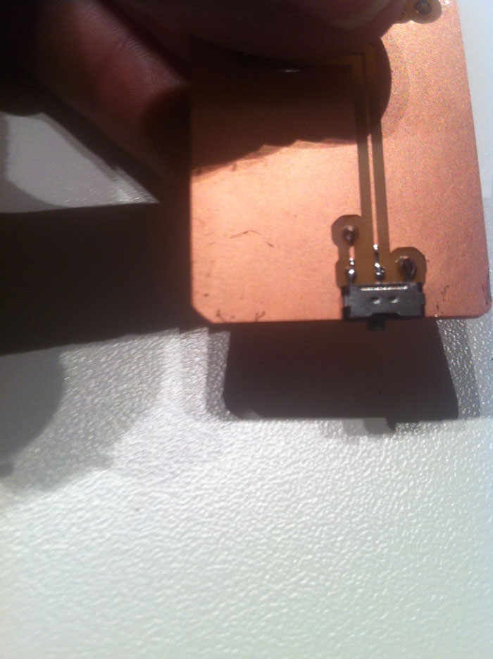
The final result is the following:
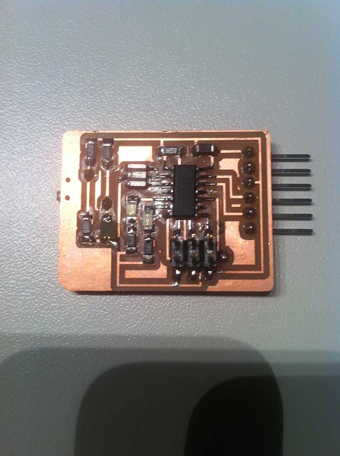
About the soldering process I documented that in less 4 and I made the connection between the two side soldering a wire passing through the holes and soldering both the side.
Many many thanks to Zaerc!
Tools
Software: Eagle, GIMP.
Machine: Roland Modela MDX-20.