Week13Networking and Communications
José J. Lazarte R.

Assignment
    Design and build a wired &/or wireless network connecting at least two nodes
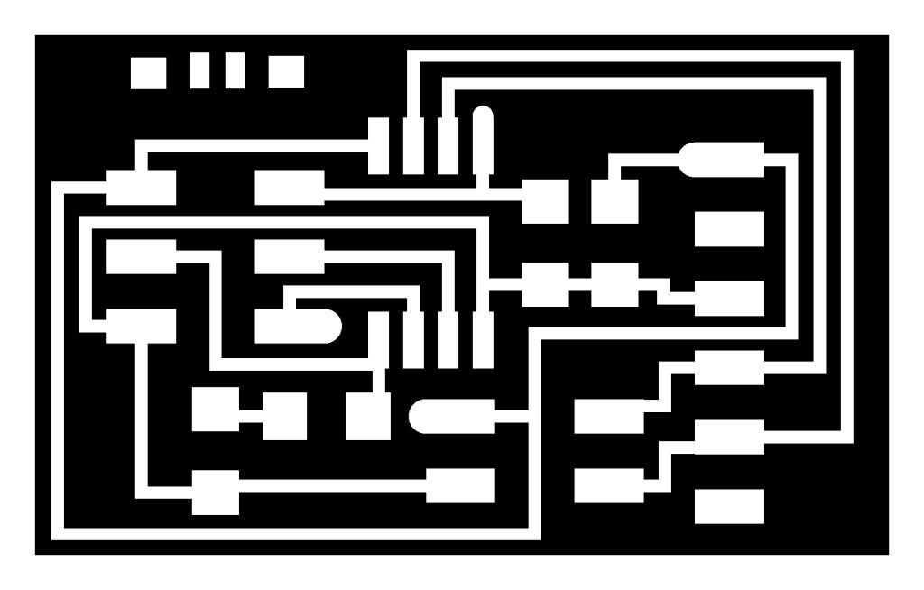
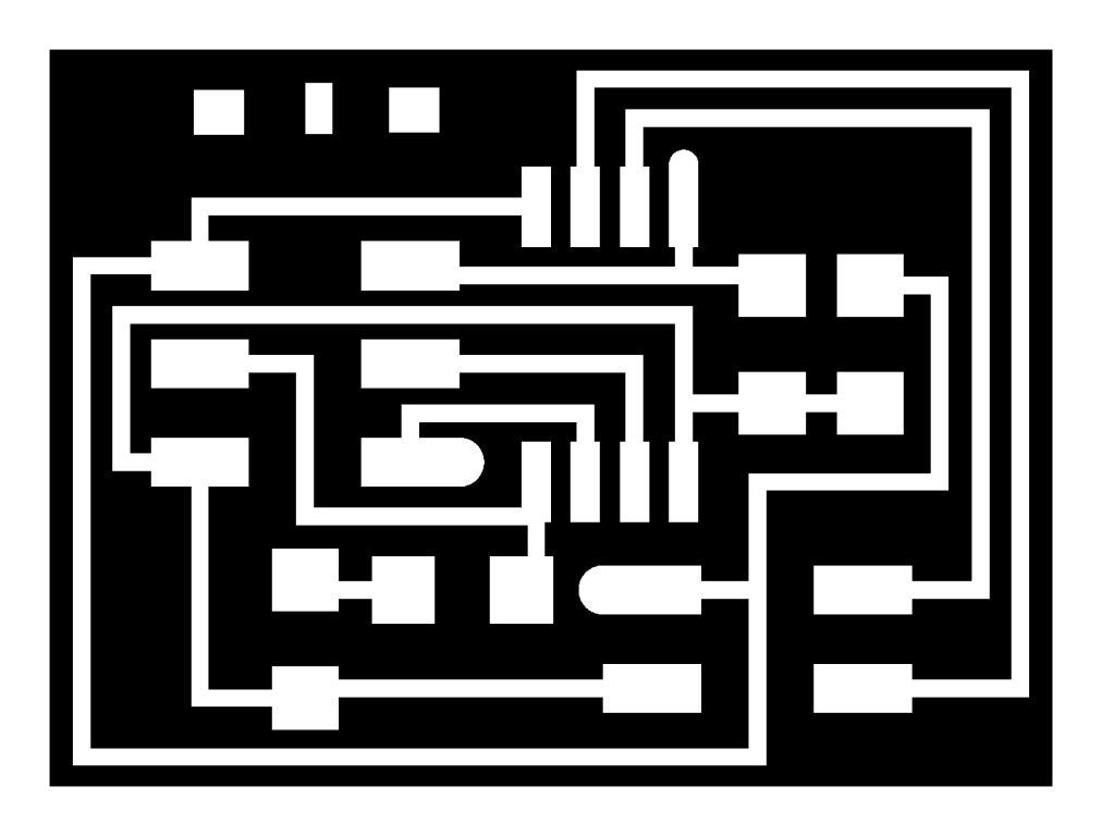
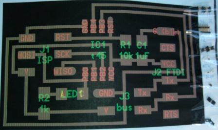
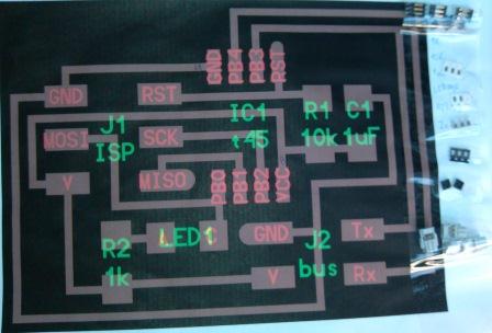
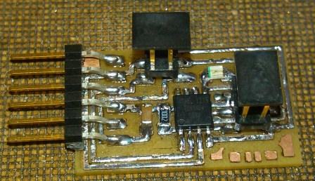
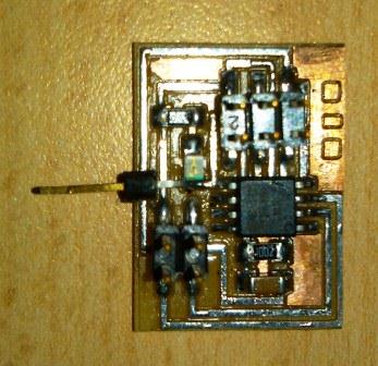
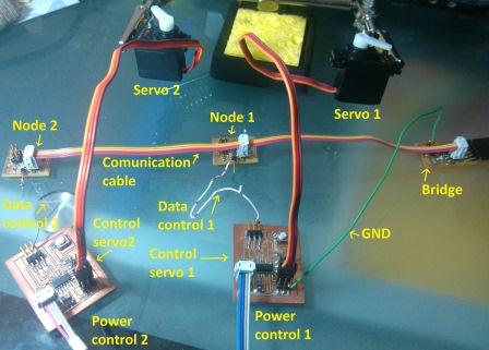
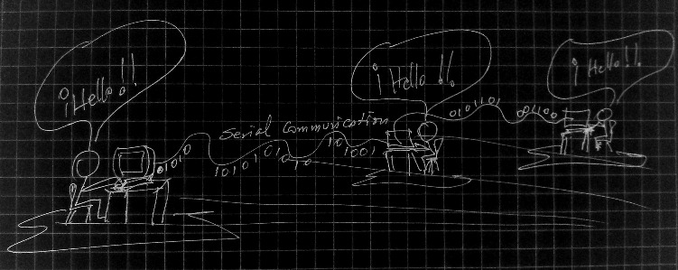
For this assignment I have decided to work using wired asynchronous serial communication, in which I can operate two output devices (servo motors) to begin i start to build one card for bridge and two as nodes.
The information for this is that the references provided for the assigment.
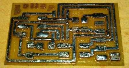
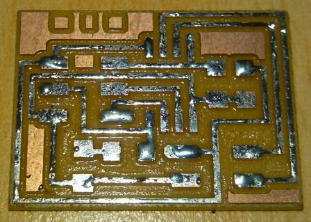
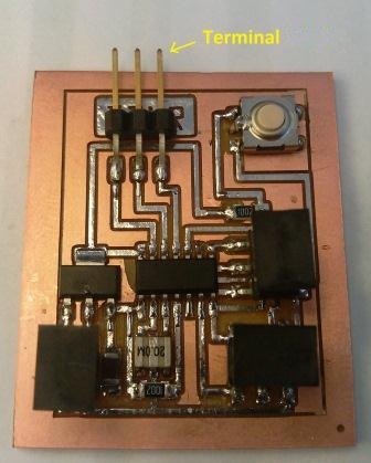
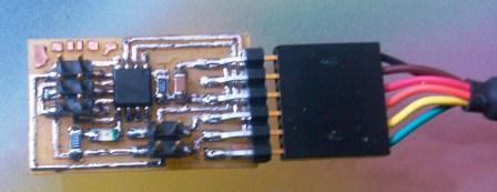
The models used for the cards are shown, with the parameters used in the Roland Modela machine.
To cards  nodes was added an output terminal to connect to the control cards for the output devices .
Control cards and output devices used correspond to the assigment 12 Output Devices, in this card one of the output is used.

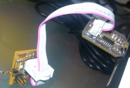
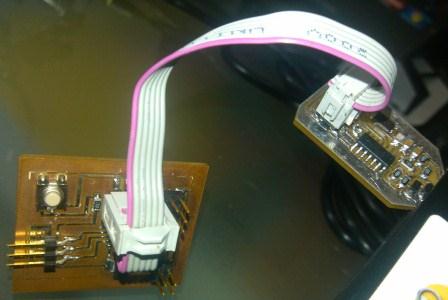
Connexion cables for serial transmission and the power of the cards was build.
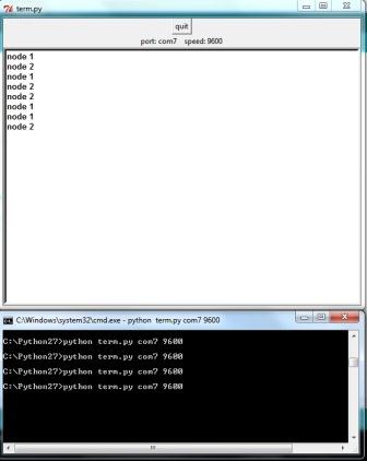
To be able to generate the information to be sent, communicated to the network nodes and the action of the end devices  a program in Python, term.py is used right through which we can send information on the serial port, the information we need to know to run the program is the port number and baud rate.
Then we need to modify programs for download bridge card and cards of the nodes. This was obtained from the information page of this assignment 13 modifications made are:

Modifications to the program that is downloaded into the bridge
card:
line 41 : #define node_id '0'
Modifications to the program that is downloaded into the node cards:
line 29 : #define led_delay() _delay_ms(1000) // LED flash delay
line 41 : #define node_id '1'         (nodo 1)
line 41 : #define node_id '2'         (nodo 2)
line 212: se omite "flash();"

To control the output devices I use the program of the assigment 12 with the following changes shown in green.
/
#include <avr/io.h>
#include <util/delay.h>

#define output(directions,pin) (directions |= pin) // set port direction for output
#define input(directions,pin) (directions &= (~pin)) // set port direction for input

#define set(port,pin) (port |= pin) // set port pin
#define clear(port,pin) (port &= (~pin)) // clear port pin
#define pin_test(pins,pin) (pins & pin) // test for port pin
#define bit_test(byte,bit) (byte & (1 << bit)) // test for bit set
#define position_delay() _delay_ms(100)

#define PWM_port PORTA
#define PWM_pin (1 << PA6)
#define PWM_direction DDRA

#define input_port PORTA
#define input_direction DDRA
#define input_pin (1 << PB2)
#define input_pins PINA

int main(void) {
   //
   CLKPR = (1 << CLKPCE);
   CLKPR = (0 << CLKPS3) | (0 << CLKPS2) | (0 << CLKPS1) | (0 << CLKPS0);
   TCCR1A = (1 << COM1A1) | (0 << COM1A0); // clear OC1A on compare match
   TCCR1B = (0 << CS12) | (1 << CS11) | (0 << CS10) | (1 << WGM13);
   ICR1 = 25000;
  
   clear(PWM_port, PWM_pin);
   output(PWM_direction, PWM_pin);
   set(input_port, input_pin); // turn on pull-up
   input(input_direction, input_pin);
   while (1){
      while (0 != pin_test(input_pins,input_pin));
      OCR1A = 100;
      position_delay();
      while (0 == pin_test(input_pins,input_pin));
      OCR1A = 1000;
      position_delay();
   }
   }
We unloaded the programs to the cards corresponding to the system and set up  interconnecting cables  by considering not single signal connections only,  also the ground. 

The procedure to complete the test run starts first with the FTDI cable to connect the USB port of the computer and the port identification obtained, in my case this corresponded to com7.
Then load the command window using  "cmd", and i go to the subdirectory where the "term.py" program is  and run it using the following command line: "python term. py com7 9600 "and the window of interaction with the network of nodes 1 and 2 appear.

Enabling node 1, node 1 LED lights up and this will send a bit to "0" to the servo control board 1, which will change position for a specified time   in the program of the control board using the variable "position_delay()" and the same for node 2. To differentiate the movements we gave different times for servo 1 (2000ms) and servo 2 (100ms). In the following video the system performans shown.

Video of operation: Video 1

References:
http://academy.cba.mit.edu/2012/students/maatta.anu/doc/week-15-networking-and-communications/
http://www.arduteka.com/2011/12/componentes-el-servomotor/
http://stackoverflow.com/questions/8491111/pyserial-for-python-2-7-2