This week's assignment
Measure something: add a sensor to a microcontroller
board that you've designed and read it.
The plan
Make the synchronous detection spread spectrum board
and experiment with that for possible use as a proximity detector
(for bird feeder project). I believe it may not have sufficient
range for the application but it will force me to learn the
concepts and coding related to this type of input device.
References
The AS220
tutorial is an excellent reference for this week's
activities.
Fabrication
The board was fabricated on the Modela milling
machine as outlined in Electronics
Production week.
Assembly
The components were assembled and connected up as
shown below.
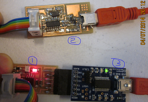
1. Hello Reflect board (newly assembled)
2. FAB ISP (previously assembled)
3. USB/Serial Interface board
Programs and Initial Checking
The following steps were taken to download programs
to my PC and perform initial check on the board.
Python 2.7.3 for Windows 7 64 bit was downloaded.
A path for Python was added using the instructions in tutorial
above.
The corresponding version of PySerial was downloaded.
Tkinter for Windows was downloaded.
PC was rebooted.
Connections were made as shown above (2 red USB cables going to
PC).
The bootloader was downloaded in Arduino environment (Arduino had
been previously downloaded).
Board is AATtiny 85 with 8mHz internal clock.
Programmer is USBtiny ISP.
LED came on and everything seemed to work so far.
Initial Programming and Debug
A modified version of the AnalogInOutSerial
Example program was run in Arduino. The modifications were to add
the software serial code and assign the appropriate LED and Sensor
pins. The purpose of the program is to read the sensor and LED
values and output them to the serial monitor.
Having set up and run the program, it was found that the values
being returned were the highest possible values (1023 and 255).
Inspection of the board showed that the resistor at R2 was an
incorrect value (49.9 labeled "49R9" versus 49.9K labeled "4992").
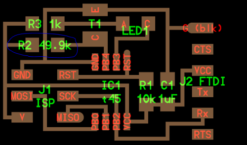
Board layout showing suspect component location
Once this component was removed and replaced the
board worked with dynamic output numbers on the serial monitor.
Those numbers changed with varying amounts of light/shade on the
LED and Sensor.
Further Programming
I ran Neil's hello reflect C program through the
Arduino interface (cut and paste code). This did not work at
first.
We experimeneted with the #define bit_delay_time and found that a
value of 98 worked.
In parallel, I ran the Python file from the Command Line to
capture the output (see below).
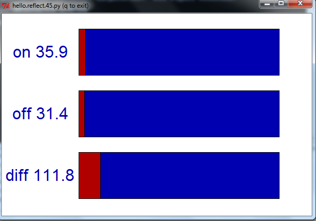
Python Output with "regular" light
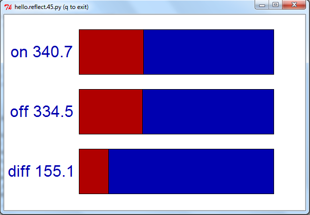
Python Output with finger in proximity to
LED/Sensor.
Also this week
I started work on the Raspberrry Pi board by
downloading all the software on to a SD card and also procuring
the correct power cable. I will work on this as we move forward
since it will be part of my final project for capturing images.