

The discussion today focused on sensing techniques.
For the TLDR version, download all my files (PCBs, Schematics, firmware and processing code). (Watch the video here for explanation.)
I decided to work exclusively with the Step Response capacitive sensors as they are the cheapest, and multi-use. I performed a pretty exhaustive study of previous capacitive sensing projects. I found lots of people using the AtTiny45 since that's what Neils's example codes were for. I wanted to test out some different geometries and button types. So I designed two separate PCBs. The first of which is just a simple Attiny44 I/O board. I break out all of the A2D pins (portA) and one pin on port B to headers. I actually utilized the ISP header since it already has some of these pins including VCC and Gnd broken out. The way it works is that you would program it, then unplug the ISP programmer and plug into a daughterboard. This will be useful for when we look at implementing Output devices later. I just have to switch out daughterboards. I designed my boards with EagleCAD and milled them from Fab Modules on the Modela. I really like that workflow.
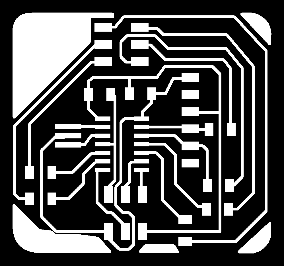
The bottom 6-pin header is the ISP header, the top one is just I/O pins.
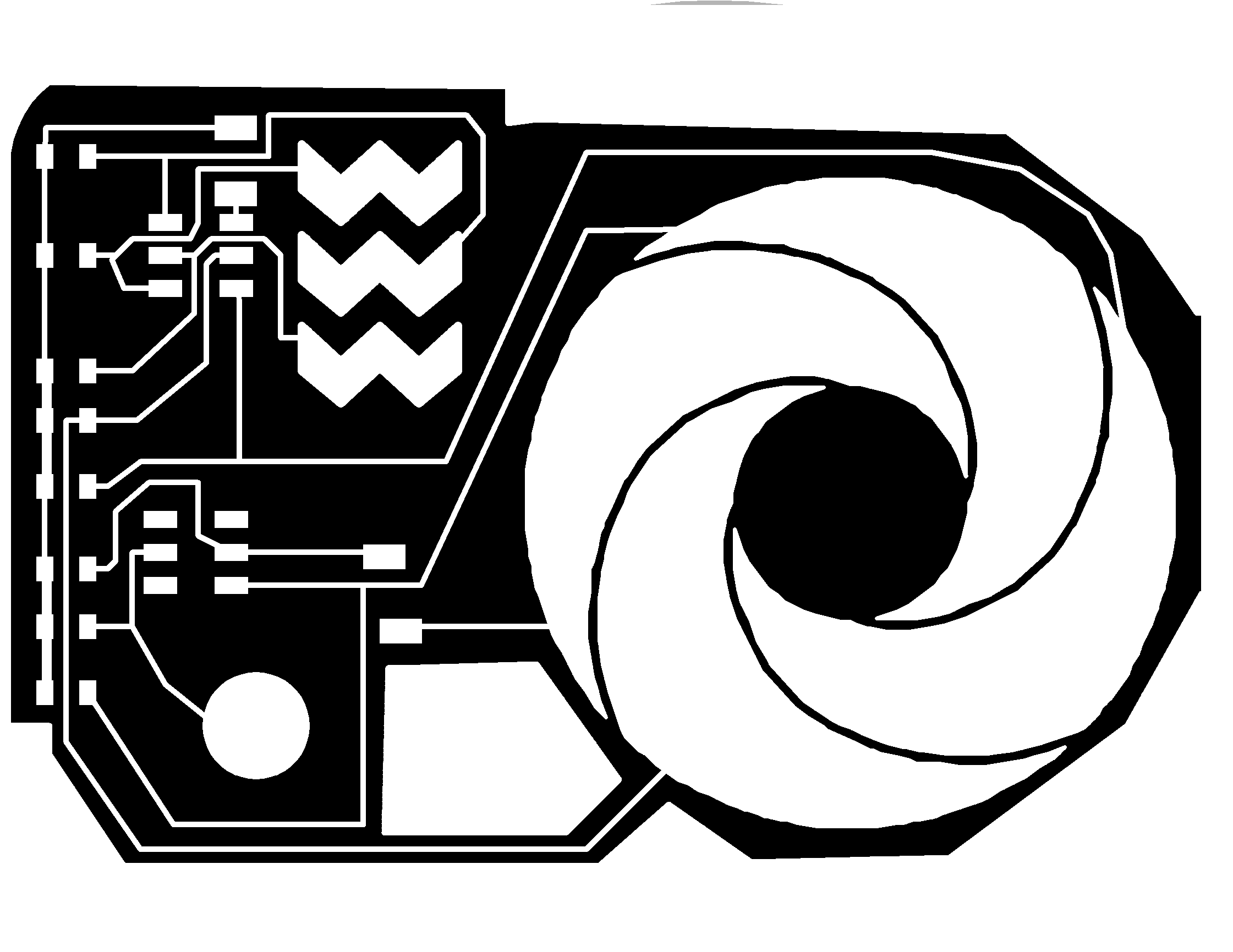
I then created the capacitor sensors on a separate board. I wanted to eventually experiment with a scroll wheel and a slider. I added a single button for good measure. For this, I looked everywhere for libraries for these shapes so I didn't have to start from scratch and I'd be able to easily reproduce the parts on later projects. I found a useful EagleCAD library with different capacitive sense designs from Pattern Agents. Below you can see my daughterboard for capacitive inputs:
As for the code, I saw many options. At first I was considering using the Arduino Capsense library. For some reason, I really like the concept of using the AtTiny chips with Arduino's IDE. Maybe since they are really simple to sketch hardware with, but I ended up not using this method.
I saw some examples of people writing it all in ASM. I can't see a benefit in doing that and it is an unnecessary hassle it seems.
I ended up modifying Neil's original example Attiny45 code for the to work on the larger AtTiny44. Since I had laid out my PCB to use PA0 and PA1 for my Rx and Tx lines of the serial output, I couldn't really utilize them for the capacitive sensing. So, like Neil's code, I just used PA2. To program it I used WinAVR and AvrDude GUI.
I set about trying to use his python code to show the outputs, but couldn't get it running in the python installation on my computer. Instead, I just rewrote it in processing starting with a bar graph example I found here.
All of my code and design files are available from a link at the top of this page. Below is a video of my processing sketch running with a single input.
Basically, I tried to copy Neil's example python code in processing. I measured the capsense on a pin at three intervals. The values were then graphed on my processing script.
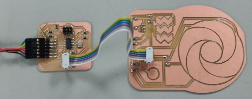
Here are a few pictures of the setup and of the processing script. You can see that at this point I had accidentally ripped off one of my 6-pin connectors on the cap sense boards.
Again, the Processing code I wrote mimics Neil's example python script. I don't really like using Python very much. This Processing code has 6 bar graphs on the screen. the left 3 bar graphs are displaying the voltage of a single pin at 3 different time periods. The right 3 bar graphs are there to display information for a second pin, however I didn't send the data over the serial for that pin so they are all static values I set them to. The numbers under the left three bars are the raw A2D reading.

This was a good enough test for me at the moment, I just wanted to figure out the guts of how everything worked for this type of sensor. Changes for the future:
(Click this link if embedded video is not working)
Web template design: davereederdesign.com