Week 6: Electronics Design
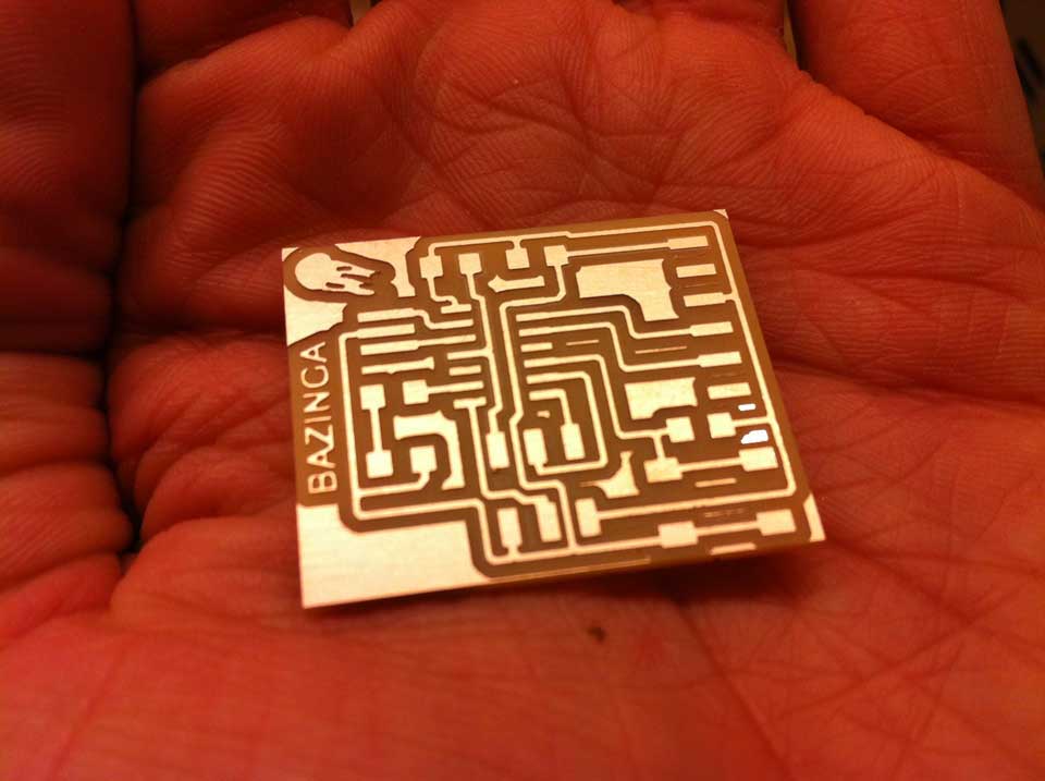
Another assignment involving electronics which are my favourite! This week we had to redesign the existing Echo Hello-World Board adding at least a button and a switch. I will explain the process that led me to the finished board that you can see in the image below.
Let the Eagle fly!
The first thing to do in order to create your board design is to download and install EAGLE Software in your OS. Go to this website and do it so: http://www.cadsoftusa.com/download-eagle/?language=en.
After installation is complete and your software is ready to use, you'll need one more thing to be prepared to start working on your board design. Eagle software and an enormous library of components, but for the purpose of this assignment, it will be better and easier to work with the libraries already provided by the academy.
Download them here.
Now that you have your libraries downloaded, unzip them to the right place:
Mac - it should be /Applications/EAGLE/lbr/.
Windows - it is most likely C:\Program Files\EAGLE\lbr\ (fact check this).
Linux - the default install location is /opt/eagle-5.3.0/lbr/ (this is for version 5.3.0, the directory may be different for newer versions).
Now everything is ready and setup to start working on your board design.
How to fly with Eagle?
Eagle is a PCB Design Software used to create the schematics and board designs for fabrication. You can use hundreds of components from Eagle's libraries and place them in your design in order to connect them to further make your board drawing. It is a simple and fun to use software (in my opinion) where you can get great results from it.
In the following paragraphs I will exlain how to use Eagle and how you can get you board design ready to go to fabrication.
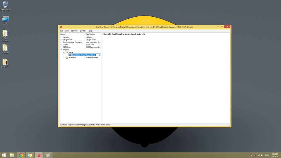
Open Eagle. The first window you'll see is this one.
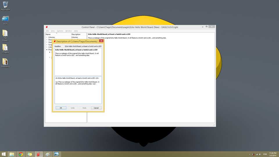
Go to File menu and start a new project. Give it a name and click Enter. Right click the new project and Edit Description. Write a short description about your project like, for example, its name and what it will do.
Now you have your project setup complete. The second thing you'll need to do is to create a New Schematics. Go to File and choose from there or right click your project and select it. Since the Schematics and Board work in parallel it is better to create a New Board as well, and save both in the same folder. By default, Eagle will save the files into your Eagle's folder created in your Documents folder. ALWAYS REMEMBER AND NEVER FORGET that you need to have both files open at all times, it is mandatory. If you by any reason close one of the files you are working on, Eagle will automatically warn you that one of them is missing because every change you make in the document will not be updated on the other one. This works both ways, bare this in mind.
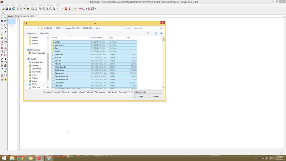
Go to your schematics and let's start working. In order to have access to your libraries, including the ones you've just added to Eagle, you'll need to tell the program which ones you want to use and make them available for that purpose. On the top toolbar there is a menu illustrated by two books, this is the menu Use Library, click on it and select Use. You will have to choose which libraries you want to use on the project you're working on. For the purpose of this one just add the libraries you've downloaded a while ago.
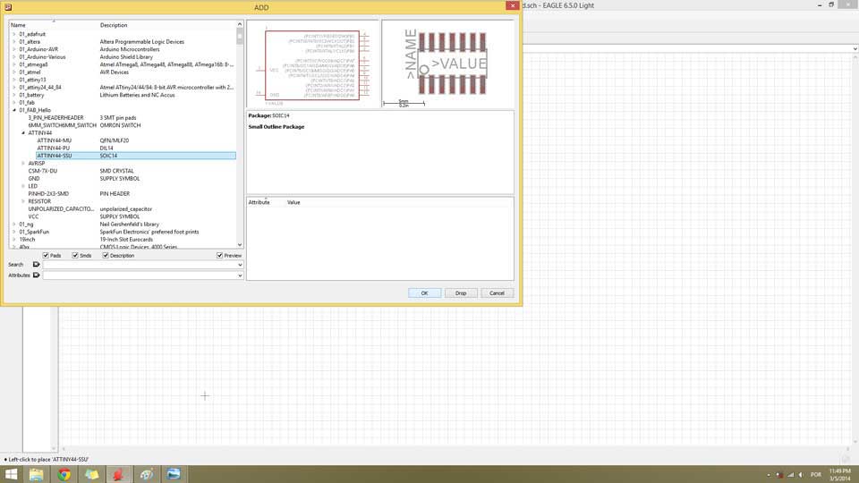
It's time to choose our first component to place on the schematics. On the right toolbar of your viewport, there is a tool for adding components right next to the one for deleting them. Click on that tool and the libraries will open for you to choose from. The first component you are going to place on your schematics its our microcontroller ATtiny44. Choose ATTINY44-SSU from the _FAB_Hello library and click ok to place it on your schematics.
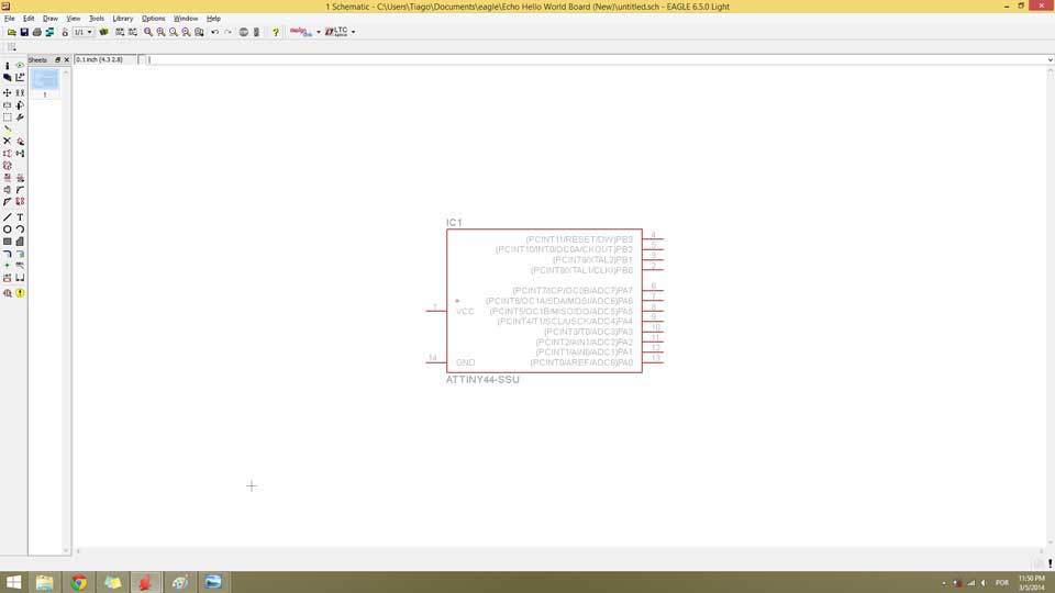
Now you have your first component placed on the schematics. You'll repeat this process until all the components necessary for this project are in place. The components necessary for this assignment are the following:
6-pin programming header: for programming the board.
microcontroller: attiny44. Once the microcontroller is programmed, the program stored in no-volatile memory. This means that it will remember the program.
FTDI header: powers the board and allows board to talk to computer.
20MHz resonator: external clocl. The attiny has a 8Mhz clock but the resonator is faster (increase the clock speed of the processor) and more accurate.
You'll have to add the following components to your schematics:
Resistor (value 10k)
Button (OMERON) switch
Ground
VCC
connect pin 10 (PA3) on the microcontroller to the button
LED (Light Emitting Diode - LEDs have polarity - the side with the line is the cathode and connects to the ground side.
Resistor (value 499 ohms) as a current limiting resistor so you don't burn out the LED
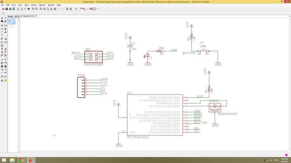
After adding all the components, it's time for some wiring, naming and labeling. You'll need to wire the entire circuit and for that you'll need to have some guides that can be found in each component datasheet. Just look for the component's datasheet on the web and you'll have access to all the detailed information about it.
NET - NAME - LABEL
When you finish it, you'll get something like this:
Eagle Takeoff!
Most of the work you're going to do with Eagle is already done! The schematics design can be, sometimes, a bit confusing but after it comes the fun part, routing the circuit.
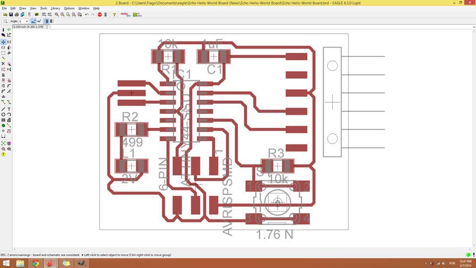
When routing, you can choose how and where the traces go, always remembering that each component has to match the connections in your schematics. To give you a little help, when you change to board view, yellow traces will be displayed to assist in the routing phase. Let your imagination flow and be bold on your design because a nice design makes a nice board. After you finish this process you'll get something like the image above.
Export your image as a PNG selecting only the top layer of your board. This way you'll only get the traces of it. Don't forget to raise the value of DPI and to export it as Monochrome.
Eagle meets Modela!
Now comes the the penult part on this assignment, milling and cutting the board. Now that you have your board ready to go, it's time to go into Fab Modules. Open the software and open the PNG exported from Eagle.
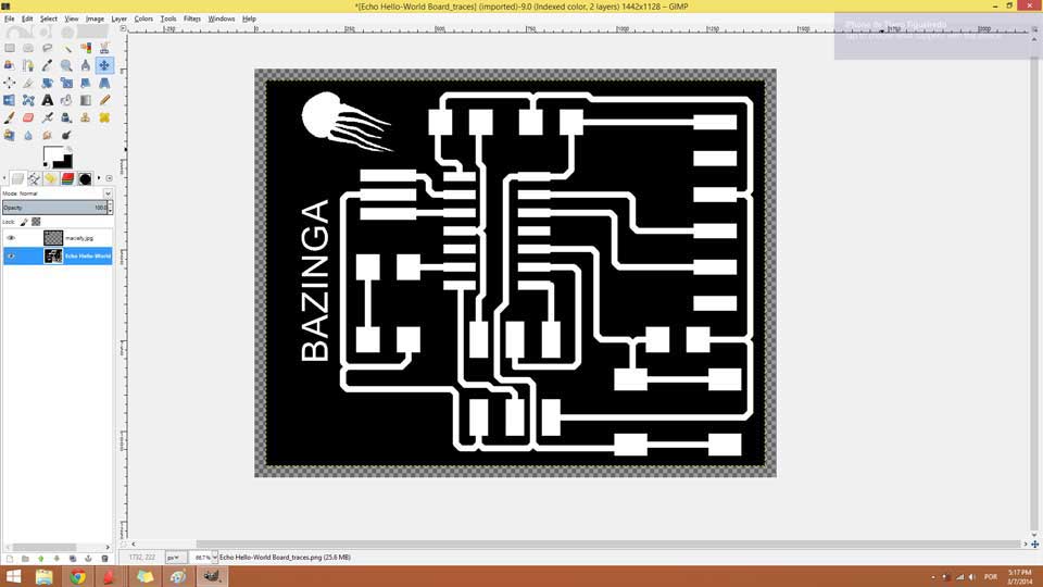
Open the image in GIMP and make all the necessary edit for you board drawing reach is final output.
Prepare all the settings needed for your board to get milled and remember the assignment of week 4 that teaches you on how to do this correctly.
Now that we have our board miled it's time for some soldering. After a couple of hours this was the result:
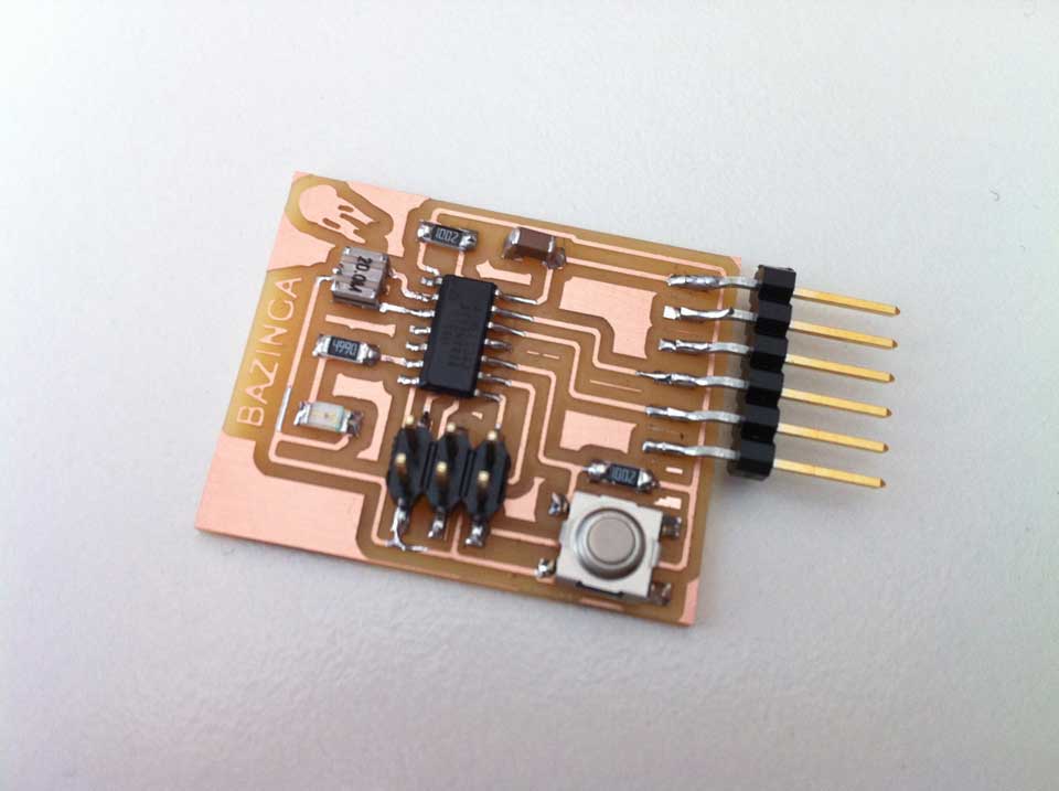
And this is the final stage of this week assignment. Hope that this documentation could be of any help. If you want a full explanation on how things are done and a really nice one from Fab Lab Providence, access the following weblinks:
Electronics Production: how to work with Modela
Electronics Design: Intro to Eagle
Project Files
Here you can download the files for this project:
Hope that this documentation could be of any help to you sharing my knowledge and experiences. Thank you for watching!
I'm loving it!