Use the right IDE
I am not sure why, but we couldn't get the attiny firmware /
board to show up in the Arduino IDE. After some
frustrating restarts and moving of files, I finally got it
working. The fix? Don't use the Arduino 1.5
version. Use Arduino 1.0. Once I went backwards
and installed the older version, things worked well. I
didn't realize 1.5 was a beta.
|
|
You can blow Regulators
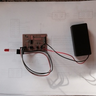
So I had the blinking working when just attached to a 9V
battery. It worked well for a few days. Then
something happened. I think I short circuited the
regulator. I used the volt meter to track things
down. I connected the volt meter to the leads / traces
and I found that the 9V power seemed to be getting right to
the regulator, but there was no voltage coming out of the
other side of the regulator chip. I tried to track it
down, but couldn't figure anything out.
I was pretty cavalier with my 9V wires as I attached them to
the pins for power. All was good the first couple of
times I did it so I stopped worrying about it.
Eventually I blew out the regulator. I am not sure how
(must have gotten wires crossed). So I ended up having
to replace the regulator.
Lesson: it is worth spending the time to create good testing
materials.
FIXES:
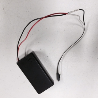
- I also took the time to wire up female connectors to my 9V
battery connection (as pictured to the right) so the raw
strands weren't floating around and hitting other pins.
- I removed and then added a new 9V regulator (not
pictured).
|
|
Software
Serial
I have used the Arduino to do many things and have used the
regular Serial library many times. Once I started to
run into problems with the sensors, I started to debug
using the serial power. I quickly learned that regular
Arduino Serial library didn't work with my board and that I
needed to use the FDDI cable and the Software Serial
library. That proved a bit difficult. Here are
mistakes made / learnings I had:
- Using the following code to debug: , first tried to get
the software serial port to connect...
if (mySerial.available() ==
true)
times_to_blink = 10;
else
times_to_blink = 1;
My first big learning was that you need to refer to the
Arduino ports using the A0 and AI (rather than 0 and
1). I had been using...
SoftwareSerial mySerial(0, 1);
. and I should have been using the...
SoftwareSerial mySerial(A0, A1);
- Unfortunately, even after getting the light to blink 10
times, I still couldn't get anything to show up in the
serial monitor using the following line of code:
mySerial.println("Hi
Mom");
Eventually I brought it in to Shawn. He taught me a
few lessons and pointed out a few additional things I was
doing wrong. Namely:
FIX(ES):
- Flipped TX and RX. It turns out TX to the board is
RX to the FDDI connector so having used FDDI connector
labels didn't make sense.
- My RX pin wasn't connected. I had checked the
connection using voltmeter, but that proved to be a bad way
to do it because RX connection wasn't solid so my tests must
have hit the trace and given me a false positive. The
lesson is that you need to also check with magnifying glass.
That's what Shawn used and he saw the issue
immediately. The other big clue here was that the TX
light went off when I hit "SEND" on some numbers.
|
|
Make sure you have a Pullup Resistor
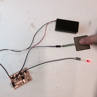
Once I had the sensors attached, I was able to see the
readings from the sensor in the Serial Monitor.
Initially, the values jumped all over the place and floated
in the 100's. Then when I pressed on the force sensor,
the values dropped to 0. The other symptom that seemed
strange was that the light didn't consistently go
on/off. It oftentimes flickered rather than shut right
off.
That's when Shawn stepped in. He'd explained Pullup
Resistors.
I changed the pinMode to "INPUT_PULLUP" and things became
far more predictable. The values also fell inline with
what the documentation said, which was that...
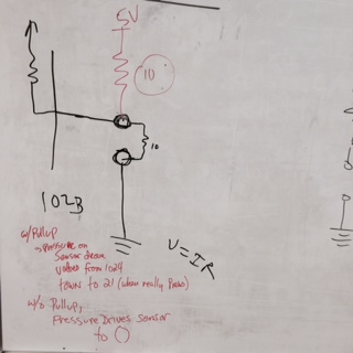
...the FSR's
resistance changes as more pressure is applied.
When there is no pressure, the sensor looks like
an infinite resistor (open circuit), as the
pressure increases, the resistance goes down. This
graph indicates approximately the resistance of
the sensor at different force measurements. (Note
that force is not measured in grams and what they
really mean is Newtons * 100!)
After putting the pullup resistor in place (from the
attiny), no touches had the readings coming in at 1024
(because there was no resistance). When I put pressure
on it, the number dropped dramatically (I could only get it
down to 21...I never got it to 0).
FIX:
The fix was SOOO simple. I added one line of code that
enabled the internal pullup resistor:
pinMode(sensorPin,
INPUT_PULLUP);
|
|