Get Voltage Divider Wired and with right values
First I wanted to see if I could get the Arduino reading changes to the velostat sensor more precisely.
LEARNING: Using Resistors to simulate the voltage
So the standard Analog to Digital converter assumes that 5 volts is the maximum value so when you do an analogRead and 2.5 volts is the voltage that it reads, it returns 512 (half of the maximum return value of 1023...2.5v is half of 5v). In my project, all the tiles with the velostat sensors behind them return a much smaller voltage, which is why the values tend to come in around 44 (out of the 1023) when at rest (aka there is no pressure on the velostat). So 44/1023 (0.043 of the total value), which I believe ends up around 0.21 volts as the value value (to figure this out, I solved for x using the following: 5/x = 1023/44). Now if we assume that, when the velostat gets hit the value doubles to 88 as a maximum, we need the new theoretical maximum to be double the .21 volts...0.42 volts. That way the AtoD converter will do the math to map the range from 0 to .42 volts rather than 0 to 5v.
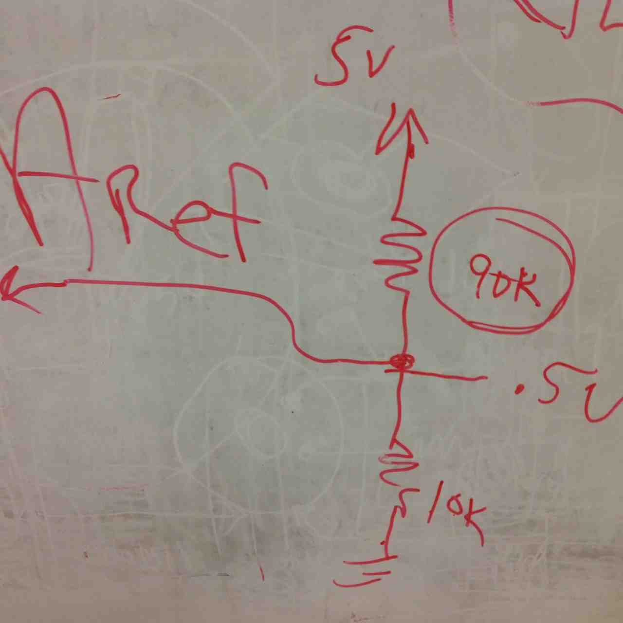
So, how do you get adjust the new maximum? You configure the arduino / attiny to use 0.4V as the new AREF (analog reference point). So how do you get the pin to read that value, you use resistors with voltage dividing. Shawn walked me through all this and the picture on the right shows how you might do that. You wire two resistors on eather side of the connection to AREF. So in the example on the right, if you want the AREF to come in at 0.5, which is pretty close to the .42 that I am looking for, you use 90K on one side and 10K on the other. That way, 90% of the charge (or 4.5v) is taken out and the balance is left (.5v).
LEARNING: Put resistors in serial to get value you want
This is obvious and has been mentioned at other times, but I want to make sure I remember it...so...
So there is no 90K resistor. So how do you simulate that? You put two 49K resistors in serial. When resistors are in serial, they are added together. So to simulate 90K (because I didn't have any 49K resistors), I put three 33K resistors together as that's what I happened to have at home. Using 3x33K resistors on one side and one 10K resistor on the other, I should end up with a voltage of:
- 99K (first resistor) / 109K (the total resistance with all resistors) * 5v = 4.541V
- 10K (second resistor) / 109K (the total resistance with all resistors) * 5V = 0.458V
Get Arduino with Different AREF value
Once I knew I could get 0.45 volts out of a simple voltage divider, I needed to figure out how to get the Arduino reading that value and changing the AREF. That brought me to the analogReference reference documentation. The following sentence messed me up:
Note that the resistor will alter the voltage that gets used as the reference because there is an internal 32K resistor on the AREF pin. The two act as a voltage divider, so, for example, 2.5V applied through the resistor will yield 2.5 * 32 / (32 + 5) = ~2.2V at the AREF pin.LEARNING: Read the data sheet first
This suggested all my prior work was useless because the Arduino hardcoded a 32K internal resistor. That meant I needed to change the values of the resistors I was going to use for this. My new math to figure out the "top side" resistance was:
32K (internal resistance) / (32K + X) (total resistance)= 0.45 (target voltage) / 5V (total voltage)To test this theory, I wired up the resistors on a breadboard with a 33K resistor on one side and three 100K resistors on the other and used the voltmeter to check what the voltage was at the mid point between all these resistors. I did two tests...
where I needed to solve for X.
32K / (32K + X) = 0.09
32K = 2880 + 0.09X
29120 = 0.09X
X = 323K
- I set it to 200K ohms to check for resistance and checked that three 100K resistors in serial delivered 99K of resistance
- I set the voltmeter to 2K Volts to check for total volts to make sure that I had about .45V coming of the center point
Get Processing Interfacing with Arduino through Serial Port
To get this going, I started by reading through and watching some tutorials about Processing. Here were the most useful ones:
- AS220 tutorial
- Processing tutorials
- OpenProcessing tutorials
- Arduino Writeup for Communicating with Processing
LEARNING: Serial Communication requires Serial.write (instead of Serial.print)
When trying to get the Arduino to communicate with the computer/processing engine, you can't use Serial.print because it will convert everything to it's ascii value. When writing serial out of attiny/Arduino, you need to use Serial.write, not Serial.print so that it sends a byte with the exact value (and not the ascII version of that value). If use Serial.print(8) it will send the ascII value for the number eight (58). If use Serial.write(8) it will send the value 8. The reading reads one byte at a time.
LEARNING: Be sure to send BYTEs not ints
So I got the Arduino sending data (the results of a sensor reading) and it wasn't working. I thought the values it would be sending would be in the 600 to 900 ranges. Instead, it was getting the resting value of ~200 and when I put pressure, which increased the values coming from the sensor to the 800's, the values dropped to between 0 and 100. Clearly I was missing something. So I changed geers and started sending constants (10, 100, 500, 1000) using the following:
void setup()Using this draw routine:
{
Serial.begin(9600);
}
void loop() {
Serial.write(10); delay(100);
Serial.write(100); delay(100);
Serial.write(500); delay(100);
Serial.write(1000); delay(100);
}
void draw()Two issues show up with this:
{
if ( myPort.available() > 0) { // If data is available,
val = myPort.read(); // read it and store it in val
}
println("Got " + val + " from serial port ");
}
1) Why are there six values for each Serial.write command? I would have thought that it would only show one line per.
2) Send int's differently. Instead of 10, 100, 500 and 1000.
That's when I found the following article on that helped me understand more of this: interpreting serial data, how serial data works and http://arduinobasics.blogspot.com/2013/04/serial-communication-tutorial-part-3.html.
This led me to the following conclusions:
FIX #1: the draw() routine was running really quickly so the value was being set and it was continually running until and printing out the value without being cleared out. The fix was to set the received value to something like null or zero so that it wouldn't continue to act as if it had gotten a new value. Basically, draw() go so quickly you need to have it handle the value and then move on.
FIX #2: I need to convert individual bytes to integers. Either I should read individual digits and convert them to integers (as suggested in this artcle) by doing some math like this: integerVar = (byte1Var * 256) + byte2Var. Or by doing something like I am doing below where I am parsing out the digits and using the int() call.
FIX #3: It took some time, but I got things working with the serial.event call. Here is my code that received information from the serial port and then processed it according to teh type of information that was passed:
// NOTE: This started with an example by Tom Igoe...And here was the Arduino code that was sending my examples:
import processing.serial.*;
int lf = 10; // Linefeed in ASCII
Serial myPort; // The serial port:
String inString; // Input string from serial port
void setup() {
// List all the available serial ports:
println(Serial.list());
// Open the port you are using at the rate you want:
myPort = new Serial(this, Serial.list()[5], 9600);
myPort.bufferUntil(lf);
}
void draw() {
if (inString.length() > 0) {
// If I get here, it means there's something in the buffer and something was returned in the serial.event routine
// println("String Received:" + inString + " - " + millis() + " - Bytes Available: " + myPort.available());
inString = ""; // resets the buffer value
}
delay(100);
}
// This routine will read in whatever is passed to it. Each thing that's passed will include a character at the front that
// will show what kind of data type it is: 'i' for integer; 's' for string and 'c' for character.
void serialEvent(Serial p) {
inString = p.readString();
switch(inString.charAt(0)) {
case 'c':
print("Character: "); // Does not execute
println(inString.charAt(1));
break;
case 'i':
String digitsOnly = inString.substring(1, inString.length()-1);
int value = int(digitsOnly);
println("Integer: Digits = " + digitsOnly + " Value: " + str(value)); // Does not execute
break;
case 's':
String stringOnly = inString.substring(1, inString.length()-1);
println("String: " + stringOnly); // Does not execute
break;
default: // Default executes if the case labels
println("Not sure...no data type"); // don't match the switch parameter
break;
}
}
/*
The following Wiring/Arduino code runs on both microcontrollers that
were used to send data to this sketch:
*/
void setup()
{
// start serial port at 9600 bps:
Serial.begin(9600);
}
void loop() {
delay(100);
//Serial.write("c"); Serial.write("M\n");
Serial.write("i"); Serial.write("10\n");
Serial.write("s"); Serial.write("Hi Mom\n");
//Serial.write(500); delay(100); Serial.write(0);
//Serial.write(1000); delay(100); Serial.write(0);
}
Got 10 from serial port
Got 10 from serial port
Got 10 from serial port
Got 10 from serial port
Got 10 from serial port
Got 10 from serial port
Got 100 from serial port
Got 100 from serial port
Got 100 from serial port
Got 100 from serial port
Got 100 from serial port
Got 100 from serial port
Got 244 from serial port
Got 244 from serial port
Got 244 from serial port
Got 244 from serial port
Got 244 from serial port
Got 244 from serial port
Got 232 from serial port
Got 232 from serial port
Got 232 from serial port
Got 232 from serial port
Got 232 from serial port
Got 232 from serial port
Get Processing to Show Bounceback UI
LEARNING: PShape objects require P2D rendering engine with size command for main window
I had code that was using the PShape command. It wasn't working when I tried to "setfill" and I got the following error:
createShape(), or this particular variation of it, is not available with this renderer.I then saw some examples that added the P2D command to the end of the size command. When changed the size command from:
size((bouncebackTileSize * 2) + (marginSize * 3) + (tileSpacing * 2), (bouncebackTileSize * 2) + (marginSize * 2) + tileSpacing);to
size((bouncebackTileSize * 2) + (marginSize * 3) + (tileSpacing * 2), (bouncebackTileSize * 2) + (marginSize * 2) + tileSpacing, P2D);...all started working with the PShape object and the colors.
LEARNING: draw(), redraw(), loop() and noLoop()...the matter
I kept running into issues with code running so quickly.
I finally read through the reference on draw(), which said the following, and it made immense sense. Once I started using redraw() and noLoop() I started getting the right flow in the program.
Called directly after setup(), the draw() function continuously executes the lines of code contained inside its block until the program is stopped or noLoop() is called. draw() is called automatically and should never be called explicitly. It should always be controlled with noLoop(), redraw() and loop(). After noLoop() stops the code in draw() from executing, redraw() causes the code inside draw() to execute once, andloop() will cause the code inside draw() to resume executing continuously. The number of times draw() executes in each second may be controlled with the frameRate()function.
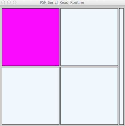
Above is the Processing window/visual with the look of the bounceback where I will have four 6"x6" tiles that will light up for kids to know that's the tile to aim for. Then on the right will be an LED strip that will light up based on how hard the ball hits the tile.
Next I turned my attention to drawing the UI and getting things working. Things were going great, until I got a java exception engine and processing screen / java started crashing. I started getting the following errors. For whatever reason, it started dying on "shape" call in the setTileColor routine. I tried debugging it all, but couldn't find anything.
+++++++++++++++++++++++++++++++++++++++++++++ Java Runtime Error when crashed:
# A fatal error has been detected by the Java Runtime Environment:+++++++++++++++++++++++++++++++++++++++++++++ Processing Engine Code:
#
# SIGSEGV (0xb) at pc=0x00007fff9533894e, pid=8700, tid=65799
#
# JRE version: Java(TM) SE Runtime Environment (7.0_51-b13) (build 1.7.0_51-b13)
# Java VM: Java HotSpot(TM) 64-Bit Server VM (24.51-b03 mixed mode bsd-amd64 compressed oops)
# Problematic frame:
# C [libGL.dylib+0x594e] glUseProgram+0xd
import processing.serial.*;
// The following set the size of the windows and screen elements
int marginSize = 10;
int LEDSize = 15;
int bouncebackTileSize = 200; // This will represent the size of the bounceback tile. There will be placed on the screen in a 2x2 matrix
int tileSpacing = 5; // This is the space between tiles
PShape topLeftTile;
PShape bottomLeftTile;
PShape topRightTile;
PShape bottomRightTile;
PShape LEDTile;
// Colors
color clear;
color isTarget;
color wasHit;
color wasMiss;
// This will contain the variables I'll need for the bounceback simulation of hits
int tileActuallyHit = 0; // This will be the tile that the user actually hit
int forceHitWith = 0; // This will be a value between 0-1023 that will show what hit
int tileToAimFor = 0; // This will be the tile that the simulator is suggesting the person it. It will be determined with a random number generator
Serial myPort; // The serial port:
String inString; // Input string from serial port
int lf = 10; // Linefeed in ASCII
void setup() {
size((bouncebackTileSize * 2) + (marginSize * 3) + (tileSpacing * 2),
(bouncebackTileSize * 2) + (marginSize * 2) + tileSpacing,
P2D );
// List all the available serial ports:
println(Serial.list());
// Open the port you are using at the rate you want:
myPort = new Serial(this, Serial.list()[5], 9600);
myPort.bufferUntil(lf);
}
void draw() {
clear = color(#F0F8FF);
isTarget = color(#FF00FF);
wasMiss = color(#DC143C);
wasHit = color(#228B22);
LEDTile = createShape(RECT, (bouncebackTileSize * 2) + (tileSpacing * 2)+ marginSize, marginSize, LEDSize, (bouncebackTileSize * 2) + tileSpacing);
LEDTile.setFill(clear);
shape(LEDTile);
bottomRightTile = createShape(RECT, bouncebackTileSize + tileSpacing + marginSize, bouncebackTileSize + tileSpacing + marginSize, bouncebackTileSize, bouncebackTileSize);
bottomRightTile.setFill(clear);
shape(bottomRightTile);
topRightTile = createShape(RECT, bouncebackTileSize + tileSpacing + marginSize, marginSize, bouncebackTileSize, bouncebackTileSize);
topRightTile.setFill(clear);
shape(topRightTile);
bottomLeftTile = createShape(RECT, marginSize, bouncebackTileSize + tileSpacing + marginSize, bouncebackTileSize, bouncebackTileSize);
bottomLeftTile.setFill(clear);
shape(bottomLeftTile);
topLeftTile = createShape(RECT, marginSize, marginSize, bouncebackTileSize, bouncebackTileSize);
topLeftTile.setFill(clear);
shape(topLeftTile);
tileToAimFor = int(random(1, 5));
println("Need to hit: " + tileToAimFor);
// Now that we have something to aim for, we need to set the color
setTileColor(tileToAimFor, isTarget);
noLoop();
println("Stopping the looping and waiting for a hit!");
} // draw()
void processHit(int tileHit, int forceUsed) {
println("Target: " + tileToAimFor);
println("Hit: " + tileHit);
println("Force: " + forceUsed);
// When get here, we've receivd the serial communication and we need to take some action
// to change the UI and tile colors
if (tileHit == tileToAimFor) {
setTileColor(tileToAimFor, wasHit);
println("Hit");
} // if...hit it
else {
setTileColor(tileHit, clear);
setTileColor(tileToAimFor, wasMiss);
println("Missed");
} // else...missed it
} // processHit
void setTileColor(int tileToChange, color colorToSetTo) {
println("Switching tile " + tileToChange + " to " + colorToSetTo);
switch(tileToChange) {
case 1:
topLeftTile.setFill(colorToSetTo);
shape(topLeftTile);
break;
case 2:
topRightTile.setFill(colorToSetTo);
shape(topRightTile);
break;
case 3:
bottomLeftTile.setFill(colorToSetTo);
shape(bottomLeftTile);
break;
case 4:
bottomRightTile.setFill(colorToSetTo);
shape(bottomRightTile);
break;
default:
println("Houston, we have a problem");
break;
} // switch
redraw();
} // setTileColor
// This routine will read in readings from the arduino that will come in the following format:
// inString.charAt(0) will represent which of the four tiles was hit...1 is top left, 2 is the top right, 3 is the bottom left, 4 is the bottom right
// inString.
void serialEvent(Serial p) {
inString = p.readString();
tileActuallyHit = int(inString.substring(0, 1));
println("Hit Tile: " + tileActuallyHit);
forceHitWith = int(inString.substring(1, inString.length()-1));
println("Force Hit With: " + forceHitWith);
processHit(tileActuallyHit, forceHitWith);
}
++++++++++++++++++++++++++++++++++ Arduino Code Sending Hit Info
/*
The following Wiring/Arduino code runs on both microcontrollers that
were used to send data to this sketch:
*/
void setup()
{
// start serial port at 9600 bps:
Serial.begin(9600);
}
void loop() {
delay(100);
//Serial.write("c"); Serial.write("M\n");
Serial.write("11023\n");
delay(5000);
}