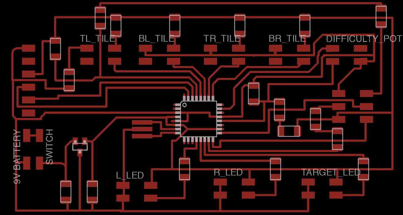
Design circuit board
The circuit board is going to need the following connections for cables:- Four 2x2 headers (one for each tile sensor)
- pin 1: +5V pullup
- pin 2: sensor cable
- pin 3: GND
- pin 4: empty / free
- pin 1: +5V pullup (this will be soldered to side 1)
- pin 2: NeoPixel control wire (this will be soldered to
side 1)
- pin 3: GND (this will be soldered to side
2)
- pin 1: 5V battery
- pin 2: GND
- pin 3: On/Off switch
- pin 4: On/Off switch
DESIGN REMINDERS:
- Put 10K pullup on RESET so doesn't occasionally reset itself
- Should put capacitors on either side of the regulator on their way to ground
- When determining the pullup resistance, you should generally balance it out with same resistance of the sensor. So for example, we measured the resistance on the copper and velostat and it came to about 1K. That being the case, we decided to put 1K resistors on the
- The capacitors on either side of the regulator should have 1 microF capacitors on either side of the regulator (and connected to ground)
EAGLE REMINDERS:
As I was using Eagle for the first time in a few weeks, I realized I'd forgotten a few things. Here are some subtle reminders that I should keep in mind when I come back to Eagle:
- You "Group Move" by using the selection tool and then "option-right-click" to get the "Move: Group" option.
- You need to "Export- Image" and when you do...1) export in monochome, 2) export in 300 dbi, 3) remove labels when export (they will mess up the traces if text going across image). To turn off labels and names, you go into the "Layers..." and turn off/hide all layers other than "Top".
- Need to export files in 300 DPI and it needs to be monochome. When I didn't do this, the image didn't have the precision it needed. Additionally,
MODELA REMINDERS:
- There's nothing you need to zero the Z axis. Where you leave it is where it starts.
- When zero'ing the Z, you want to lower it until you see some shavings pop up.
LEARNING: AVCC and VCC
So I have been confused by the fact that the ATMEGA has a bunch of VCC/AVCC and GND pins. Do all these need to connected by traces? Are the connected internally and don't need external/trace connections? I struggled with this one when working on my board design. Here is resources I came across that explained things: AVCC/VCC connections. Additionally, Shawn confirmed for me that I needed to connect them all.
LEARNING: Need different eagle package for 328 chip
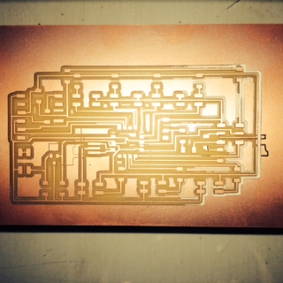
The first draft didn't work. If you look closely at the ATMEGA pads, they aren't all cut out the way they should be (it's in the middle of the board). The issue is that the pads on the ATMEGA library that I used had pads that were so big, the 1/64 mill wouldn't fit in. After showing it to Shawn, he pointed me to this writeup about how to get Eagle to setup the pads in the right way if you want to use the 1/64 mill. The fix? If modeling the ATMEGA328, you need to use the ATTINY88-THIN package in Eagle.
LEARNING: Programming/Soldering the board is hard
So I started trying to program the stuffed board. First, I was getting the following error:
avrdude: Device signature = 0x535353
avrdude: Expected signature for
ATMEGA328P is 1E 95 14
After digging into this (and reading lots of forum posts), I found that there was a REALLY small piece of solder that was causing two of the pins to touch. Once I fixed the solder, this error disappeared. Thank goodness for the forum posts.
Draft 2 Notes:
I made two changes with the second draft...1) I used a different library/chip/part for the ATMEGA. This should give me better traces for the ATMEGA328.
2) I added a header for the potentiometer in the top right.
Stuffing Notes:
Be gentle...It turns out that, once again, I broke off the headers. After spending hours stuffing the board, the FTDI broke off...and it tore off the traces. AAHHH...hours wasted. I will head to Providence to mill some more boards on Tuesday.LEARNING: Export the full window from Eagle to Modela
When you export from Eagle, you have the option of exporting the "Area" or the "Window". Previously, I had been exporting just the area. This time I exported the "Window" and by doing this I got the entire board. Before I'd done this, the bottom trace was missing a milling on the bottom so it ended up being attached to the entire ground. See image at right to see what I'm talking about.
Draft 3 Notes:
I didn't change a great deal with Draft 3. Here were small changes:1) I fixed up a few extraneous spots where it was causing weak traces.
2) I also fixed the size of the board so that the ground didn't merge into the top trace.
LEARNING: RX/TX for FTDI board...triple check have it correct. Now that Draft 3 was soldered and ready to go, I started integrating the program I'd written for the Arduino with my board. And the first issue was that I couldn't get the software serial debugging to print out. I used some pins to switch the TX/RX and...low and behold...it started working again. Rookie mistake! Even though I'd checked this twice by comparing my old board to the new one I was designing. So I changed my schematic, but for the final project I am going to likely just use cables to swap them.
LEARNING: The boards.txt Programmer matters if using the ATMEGA328
So I now trying to program things. I keep getting the following error:
avrdude: ser_recv(): programmer is not respondingIn digging into it (and talking to Shawn, the problem was that I connected the reset pin through the 10K pullup (rather than the reset trace) so I couldn't, which meant I couldn't program the board directly by just going through the FTDI cable. So now I need to find a way to program the bootloader using the STK500 and my boards.txt needed to show that I was using it. I started digging into this one and I came across the following:
avrdude: stk500_recv(): programmer is not responding
http://stackoverflow.com/questions/19765037/arduino-sketch-upload-issue-avrdude-stk500-recv-programmer-is-not-respondi
...which suggested the following:
- if the cable and/or connectors does not have microcuts ;
- if there is no shortcut on the PCB between Rx and Tx (usually pins 1 and 0) ;
- if the atmega chip is not out of power (GND/VCC shortcut or cut or VCC input being dead…) ;
- if the 1 and 0 pins of the Arduino are not being used by some shield or custom design (/!\does not apply to the leonardo as it has independent USB handling)
- if the USB to UART converter does not have a problem (FTDI on older duemilanove or Atmega16U2 on newer Unos) ;
- if the Atmega328 chip is fried or wrongly installed ;
- if the bootloader has been overwritten or is failing…
#######################
uno.name=Arduino Uno
uno.upload.protocol=arduino
uno.upload.maximum_size=32256
uno.upload.speed=115200
uno.bootloader.low_fuses=0xff
uno.bootloader.high_fuses=0xde
uno.bootloader.extended_fuses=0x05
uno.bootloader.path=optiboot
uno.bootloader.file=optiboot_atmega328.hex
uno.bootloader.unlock_bits=0x3F
uno.bootloader.lock_bits=0x0F
uno.build.mcu=atmega328p
uno.build.f_cpu=16000000L
uno.build.core=arduino
uno.build.variant=standard
Once I removed those, I was left with the following...and these lines made everything start working. Yeah...
#######################
psf_uno.name=Arduino Uno (using different boot loader)
psf_uno.upload.maximum_size=32256
psf_uno.upload.speed=115200
psf_uno.bootloader.low_fuses=0xff
psf_uno.bootloader.high_fuses=0xde
psf_uno.bootloader.extended_fuses=0x05
psf_uno.build.mcu=atmega328p
psf_uno.build.f_cpu=16000000L
psf_uno.build.core= arduino:arduino
psf_uno.build.variant=standard
LEARNING: Can't forget about internal resistor with AREF
As I was reading through the AREF references and postings, I came a cross this article that suggests:
The ATMega328 datasheet confirms the "internal 32k resistor" reference in table 29.16 ADC Characteristics with: Reference Input Resistance = 32 kOhm.Having looked at this, I realized my plan for the AREF pin and resistors might not work. To get around this, I ended up going with the analogReference(INTERNAL) command and I ended up with the same impact...my sensors were being measured against 1.1v rather than the 5v.
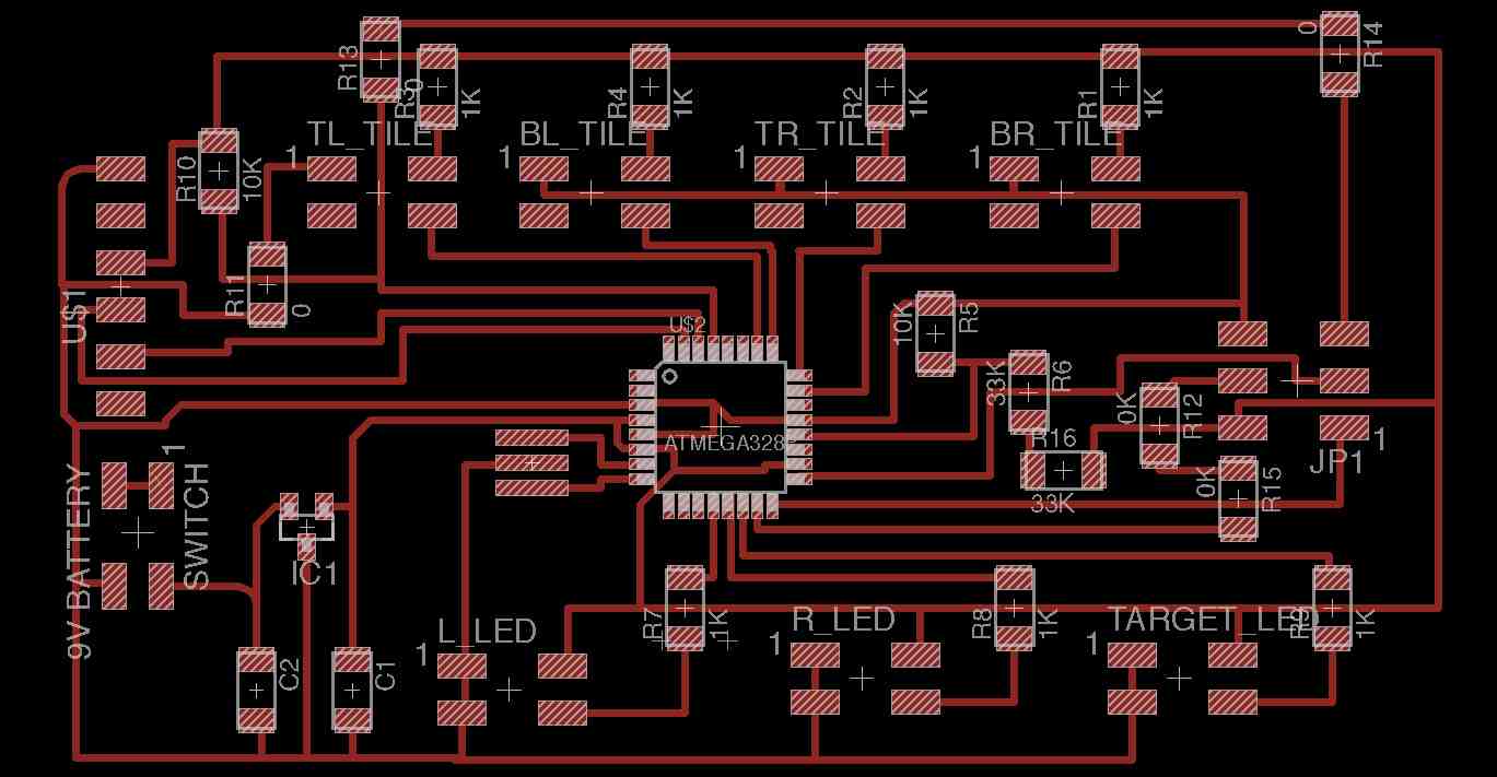
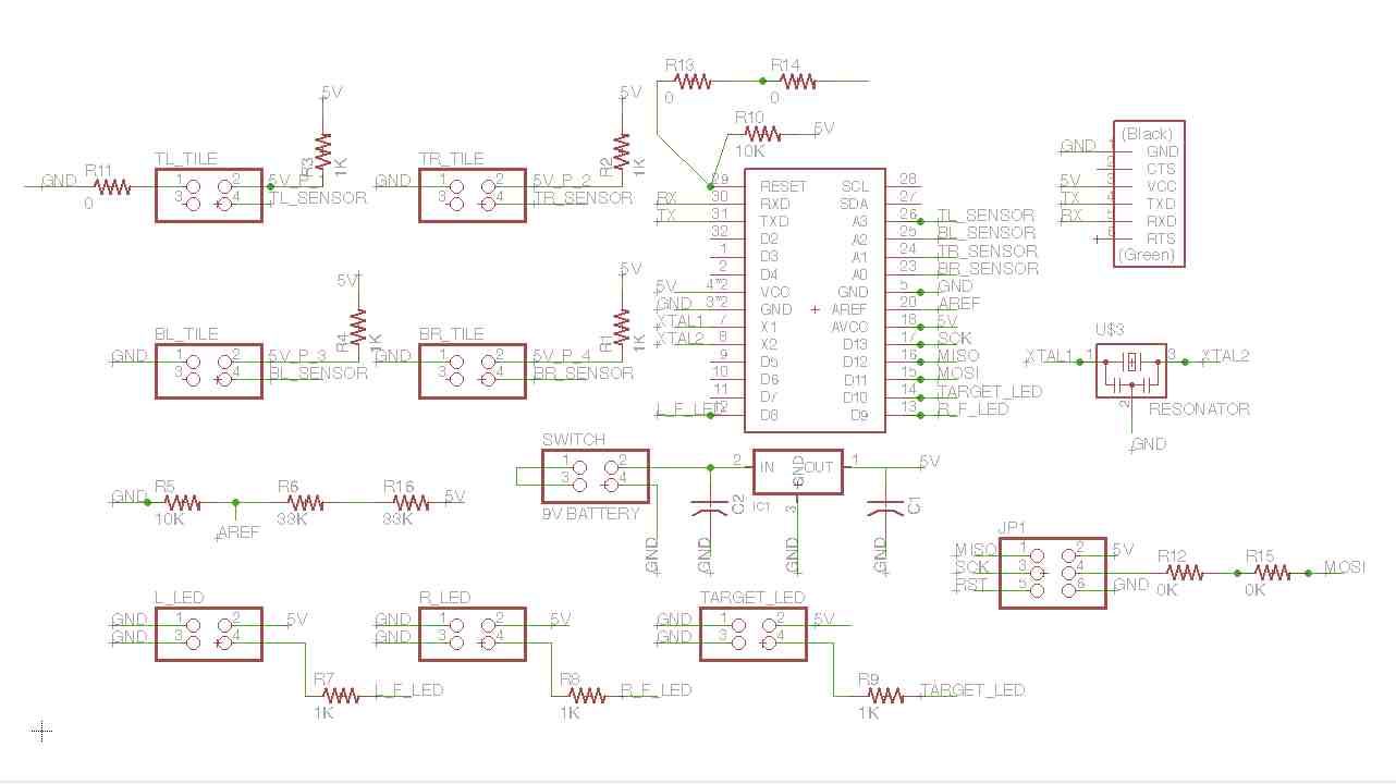
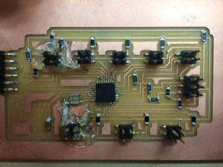
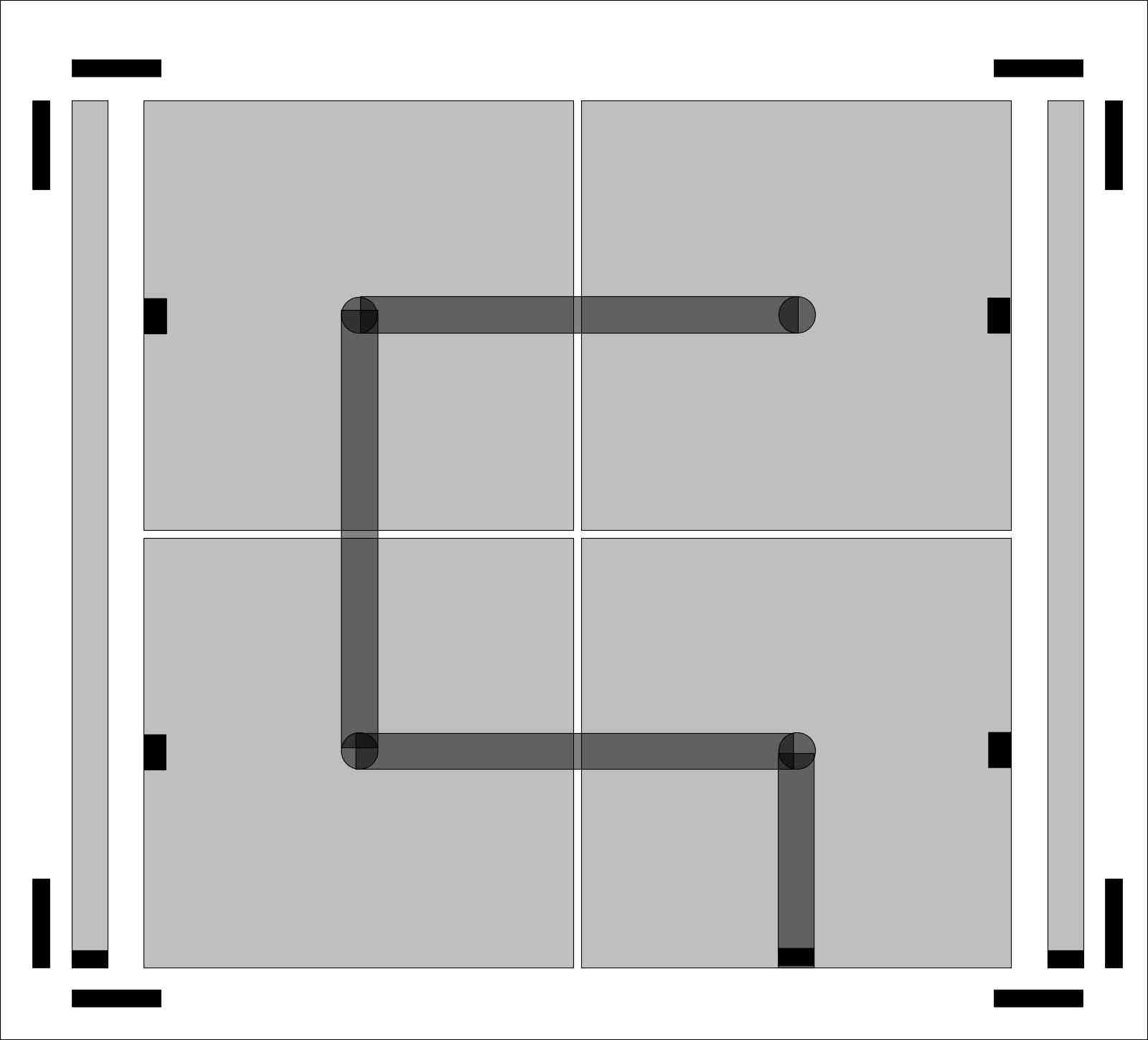
Draft 1: Board Design
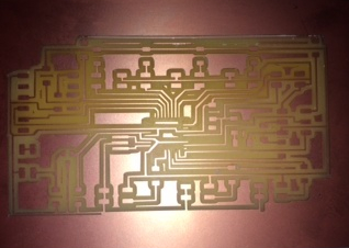
Draft 2 of board...
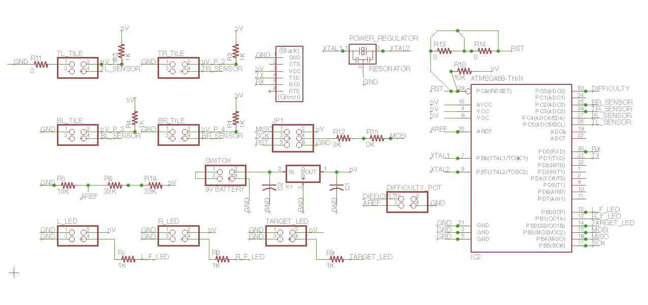
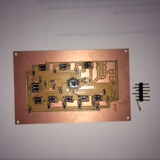
Draft 3 of board
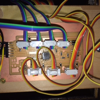
Final Board
So when all was said and done, the
final board ended up being Draft 3 needing some
jumpers and a glue gun. I learned that the
physical studiness and design of the frame can cause
significant problems for the small traces.
Twice the frame (and some short wires), pulled the
headers off the board, which lead to three different
jumpers being added (with the corresponding glue gun
holding things down.
Create Frame
So for the frame I plan to have the items cutout on the ShopBot.SHOPBOT REMINDERS:
It had been a few weeks since I used the ShopBot. That being the case, I decided to document all the things I had "forgotten"...
- Need to jump through some hoops to get a good file that will transition well from InkScape to VCarve. More specifically...need to convert everything to a path and need to export as EPS (is better than PDF).
- For some reason, paths that I cloned and rotated all had triple the lines they should have. To get around this, I just redrew the paths in VCarve.
- The pass depth needs to match the diameter of the tool...and you generally want that to be the same as the cut depth, unless it is a hard serface. If it is foam, you should make the cut depth double the diameter of the tool. If it is hard wood, then you want the depth to be
Draft 1:
Draft 1 looked pretty good. The LEDs strips fit. The target LEDs fit.
Draft 2:
For draft two, I changed the following things:- I went to wood (instead of insulation foam)
- I got rid of the strap holes because I am going to change how
- I changed the corners from being square to being "angled". The primary reason was because I am going to attach o-ring screws
- I moved the wire cutouts so that they all came through next to each other. This will make running the wires easier.
Here's a link to the Inkscape file I used...
LEARNING: Pay more attention to mill I use
So Draft 1 was cut out of insulation foam. I used a 1/2" straight edge mill. It cut wonderfully. When I went to do the same cuts, but this time with wood, the bit got caught up even though I made the cut depth 0.1" and the 0.5" mill. That messed up all the cuts because the ShopBot got caught up and forgot where it was so it messed up all subsequent cuts. Instead, when cutting wood you need the bits that cut using the circular bits...not the flat bits.
LEARNING: Use better wood
The wood I used wasn't very sturdy and it flaked a bunch. I should have used a piece of plywood that was wood all the way through.
Draft 1 of Frame
Picture of initial InkScape design
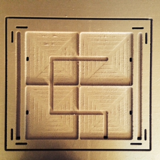
Initial ShopBot milling of insulation
Draft 2 of Frame (made out of wood)
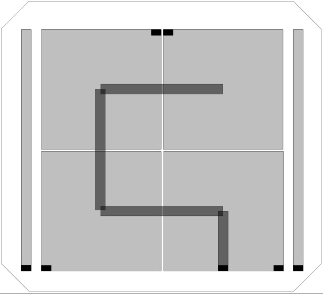
Draft 2 picture of Inskape design
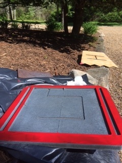
Draft 2 after being painted.
The Backing/Stand
There are going to be two parts to the backing...1) the stand so that the board can be placed on the ground.
2) a box that will hold the electronics
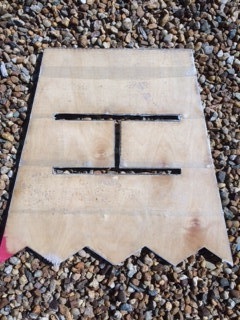
The box will need holes for things to run. And instead of putting small holes for individual wires, I cutout a big H so that the wires could come through at any point.
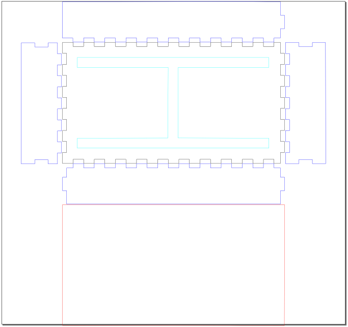
Draft 1 (of the Box):
The Box is going to house the electronics. It is going to be mounted on the back side of the stand. It will hold the circuit board on the right. And ultimately, it will hold the battery on the left side (although I am not going to put the battery into place until after the presentation...for the presentation I am going to just use the FTDI cable from the mac.I am thinking of mounting all the electronics inside the box and then will connect the box to the stand once I have everything working. The hope is that the box will be easy to carry around (and will keep the circuit board from getting hurt. I also plan to mount the on/off button and the potentiometer on the top of the box (hence the circles and
Here are the different cuts on the box...
1) The cyan (sideways H) will be cutout of the board so that wires can be run through the back of it.
2) The red is the top. This doesn't have groves because I am going to need to get into the box so I am going to put hinges and a flat top so that I can get in and out of the box.
3) The dark blue are the sides.
Draft 1 (of the Stand):
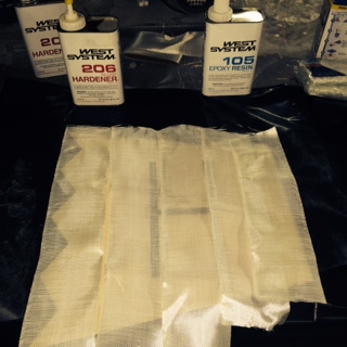
The stand is going to be connected to the back of the target with a hing. It is going to swing out so that the back is supported when the ball hits (and the target is on the ground rather than hanging by the eye-screws). Once I lasercut the backing, I wanted to give it more strength so I fiberglassed it. Here are the pictures of that work...LEARNING: Simple fiberglassing is not hard...
Having not fiberglassed before (I was on a school trip during the composits week), I found this to be pretty simple to do. I plan to do it again on a more complicated object in coming weeks.
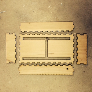
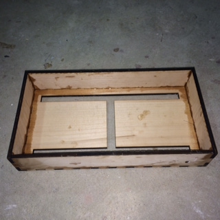
Box Plans:
Box Assembly:
Draft 1 (Stand):

Stand Finishing
The Programming
In order to get all this programming going, I thought I'd start by getting it working on the Arduino. My basic theory was that, because I am using the ATMEGA328 and because I am using a 16MHz resonator, then it is basically the same thing as an UNO.Draft 1:
So for the first draft, I decided to program the entire thing using the Arduino. My reasons for doing this were:
1) It made writing code and testing quicker
2) It reduced complexity. By doing this, I didn't really need to worry about my soldering or any other issues with my circuit board
3) It provided me an easy way to use experiment with the different resistors and the things I wasn't sure about (e.g. potentiometer)
To do this, I used an Arduino, a breadboard and some big parts (resistor, potentiometer, etc). Yes, I realized that there could be problems with the wiring, but I was able to really quickly test things with the voltmeter and the serial monitor in the development environment.
LEARNING: Pay attention to typecasting
I wanted to get an percentage value, that I wanted to be an int, by dividing two integers. I originally had (note, reading and num_of_LEDs_in_force_strips are integers):
int percent_to_use = int(reading / num_of_LEDs_in_force_strips);
...that didn't work. I ended up with...
int percent_to_use = int(((float)reading / (float)num_of_LEDs_in_force_strips) * 100)
...I didn't realize I needed to typecast the ints to floats before dividing.
LEARNING: Arduino resets itself when it crashes/hits error
My program kept resetting itself, but I actually thought it was something else. I thought it was because I had a problem with the flow of execution and that it just kept looping, but I was wrong. After troubleshooting a bit (and Shawn advising me), I found that the problem was that I hadn't initialized a variable. Just knowing that it resets itself will be helpful as I won't track down things incorrectly in the future.
LEARNING: pins_arduino.h is a popular file (and arduino
I started playing with boards.txt to resolve the fact that the programmer wasn't responding. I changed boards.txt around so that I could use a different way of loading the program. As I did it, I was getting the following error:
/Applications/Arduino 1.0.5.app/Contents/Resources/Java/hardware/arduino/cores/arduino/Arduino.h:213:26: error: pins_arduino.h: No such file or directoryThat's when I read the following write-up that explained there is a bug in the Arduino 1.0 code. It said the following:
Final_Project_Code:9: error: 'A0' was not declared in this scope
Final_Project_Code:12: error: 'A5' was not declared in this scope
Final_Project_Code:13: error: 'A4' was not declared in this scope
Final_Project_Code:14: error: 'A3' was not declared in this scope
Final_Project_Code:15: error: 'A2' was not declared in this scope
Copyed pins_ardino.h file from \Arduino\arduino-1.0.1\hardware\arduino\variants\standard to D:\Arduino\arduino-1.0.1\hardware\arduino\cores\arduino and problem has gone.I moved the file and things starting compiling.
But I think Arduino team should patch this anyway.
LEARNING: NeoPixels start numbering at 0
I initially programmed the NeoPixels starting at 1. After re-reading this article, I realized they start at 0 based on this...
The first argument — n in this example — is the pixel number along the strip, starting from 0 closest to the Arduino. If you have a strip of 30 pixels, they’re numbered 0 through 29. It’s a computer thing.Doh...off by one...
LEARNING: Build in constants so can easily configure and test
I had four sensors. When I ran the configuration and measured the results on the four sensors, they had different readings (ranging from 85 to 350). This made being able to iterate on the programming and trying different ways to improve the accuracy important. So I set up a bunch of global constants that I used to improve the accuracy. Each time a sensor was read, I put it through the map() function to determine if there was a noticiable change. The following line was used:
map(sensor_reading, // the reading
baseline, // "from low value" : the calibrated baseline
baseline + sensor_max_range, // "from high value" : the baseline plus constant
1, // "to low value"
num_of_LEDs_in_force_strips); // "to high value" : the
- sensor_max_range: This originally was the "high
bar" for the range of each sensor (without the aded
'baseline'). I then realized that I couldn't have
one constant "high bar" for all sensors because they had
different baselines. Instead, I made this the
number I would add on top of each baseline to determine
the maximum. It make it so the high value would be
relative to the baseline rather than one constant value
for all sensors.
- minimum_force_to_trigger: This is the number
that needs to be hit before a hit is triggered. If
it is too small, then I will get false positives.
If it is too large, it won't register a hit easily
enough. Because of the map reading above, each
sensor reading was being mapped to a value between 1 and
10. I started by making this a 3, which was
basically saying I needed a 30% increase in the sensor
reading. It became too hard to cause "a
hit". I then moved this to "2" and things started
working better.
- sensors_to_track: I found that each sensor had
different performance/characteristics. So to
make it easier to test, I created a constant that would
let me turn individual sensors on/off by using bitwise
logic where each bit in an integer represented one of
the sensors.
Draft 1: Arduino with breadboard for Programming
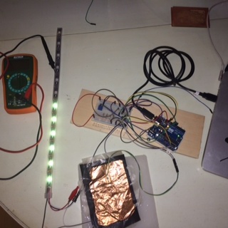
Initial testing with old velostat and force strip
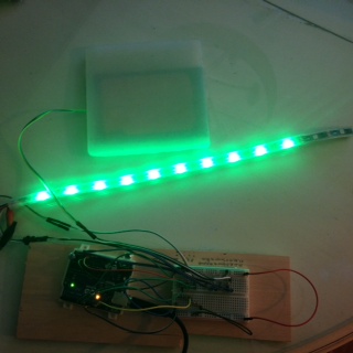
Arduino Test Environment with one light strip and sensor
Tiles
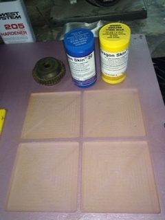
Molds / Silicon Tiles:
When I did the initial molding and poring of the tile molds in week 9, it took a large amount of silicon to fill the tiles. This was largely because I was making cable runs for the LEDs. It occurred to me that I didn't need to do this. Instead, I could mill out the cable run on the frame and that the tiles could be a simple 1/4" x 6" x 6" piece of silicon that would cover the sensors. So I used the frame design to cut out four of these into a piece of insulation as the mold.
Draft 3 (Dragon Skin)
For draft three I used my remaining half bottles of Dragon Skin. I was going with Dragon Skin because it is see-through, which means the target LEDs will be seen so the kids will know what to shoot for. Using the new mold I milled out with the ShopBot, I pored and made two new tile covers (unfortunately, I didn't have enough Dragon Skin to do the final two). They turned out great.
Draft 4 (ReoFlex)
After three trips to the RISD store in Providence, I couldn't get any more Dragon Skin for the project. They ran out because it was the end of the term and, even though they said they'd order more, they didn't (and I'd run out of time). So I decided to try another kind of silicon, ReoFlex, for the last two tiles.
LEARNING: ReoFlex is harder to get "just" right
When I did the ReoFlex, I found that, eventhough I stired it longer than the Dragon Skin much longer and it dried for more than 24 hours, it still was takey / sticky. It became really annoying to work with; whereas, the Dragon Skin was very easy to use.
Draft 3 (simple 0.25" mold)
Dragon Skin Prep
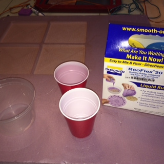
ReoFlex Prep
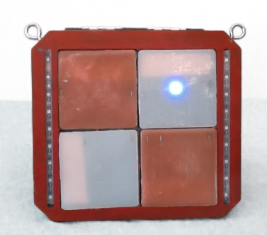
All modes (2 Dragon Skin, 2 ReoFlex)
inside Frame
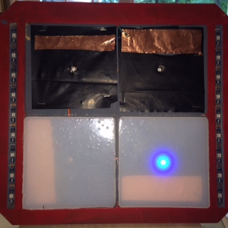
Sensors
Using the Inkscape file for the frame, I cutout the copper for the sensors. I then attached them to the velostat. One example of the final sensor cutouts is pictured to the right (the bottom left cutout). And I started wiring and programming one of them. Alas, I immediately ran into issues.LEARNING: Ratio of Velostat to Copper matters
First issue was that all the readings from the sensor were coming in at 1023. This suggested there was no resistance at all from the velostat when it was completely covered by the copper. Here were the resistance readings on the voltmeter for the first three sensor drafts.
Draft 1 (top left): 29 ohms (29.4 reading on 200 ohm setting)
Draft 2 (bottom left): 4.9 ohms (4.6 reading on 200 ohm setting)
Draft 3 (right): 860 ohms (0.43 reading on 2K ohm setting)
So clearly the higher percentage of the velostat that was covered by copper, the smaller the resistance. I then experimented with putting about an inch wide sheet of copper across the top and it gave me some better readings. So I ended up going with the roughly 1/6th coverage.
Initially I didn't think it would make a difference if the sizes weren't identical. My reasoning was that my calibration routines would resolve any small differences. I finally ended up with four sensors with approximately sensors with approximately one wide sheets of copper
LEARNING: Distance between places wires are attached matters
As we were testing, we started playing with moving the wires to different sides of the velostat. I had initially wired them in the same corners, but just on different sides- largely because it was easy to run the wire to the same place. As we tested the resistance, it became clear that the amount we could probably just put small pieces of copper in different corners and that that would dramatically change the performance of the sensors. Bottom line: I probably should have tested more of this.

First three velostat test sensors
Frame with two sensors showing and two covered with Dragons Skin
Frame with two sensors showing and two covered with Dragons Skin
Putting it all together
At this point I believe I have all the parts I need...the frame, the backing, the code/program, the tiles. Now I need to wire and attach it all together.LEARNING: Use thicker backing
When connected the backing to the square frame, I did it using hinges. The problem was, most of the screws that came with the hinges were 1/2" long. The problem was, the board was 1/4" thick. This meant that the screws stuck out the back. Originally I wasn't worried about the thickness of the backing / stand because I knew I was going to fiberglass it- I never thought of the fact that the screws might be longer than that.
LEARNING: Think through all methods of attaching first
I took for granted the fact that I was going to need to attach the wires, sensors and silicon tiles to the frame. Unfortunately, I didn't think through it all until I had all the parts made. Fortunately, I was able to come up with a quick way with a stapler for the wires. I wondered if this was going to cause problems with electricity, but it didn't. The same thing worked with the sensors and the staple gun. Unfortunately, I tried the same thing with the silicon and that didn't work too well.
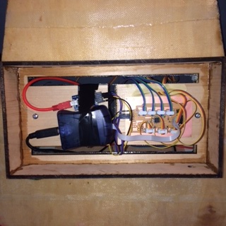
Back after being put together
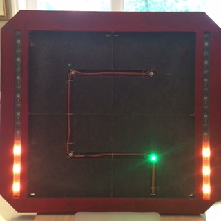
Frame with LEDs installed
Tiles with Velostat and Dragon Flex mold / covers
Frame with LEDs installed
Tiles with Velostat and Dragon Flex mold / covers
