Week Six: Electronic Design
Goal
The goal for week 6 is to redraw the echo hello-world board, add (at least) a button and LED (with current-limiting resistor), check the design rules, and make it.
For extra credit simulate what the board will do.
Week Six: Electronic Design Objectives
- Play with different electronic packages
- Eagle
- FreePCB
- Cut out board
- Solder board
- Test board
Play with different electronic packages
Eagle
Had a tough time finding all the parts in the eagle libraries
Got length from spec sheet and I used that to pick the correct sm resistor. Length is 3.1 m.
Then I just copied the other resistor already on the board.
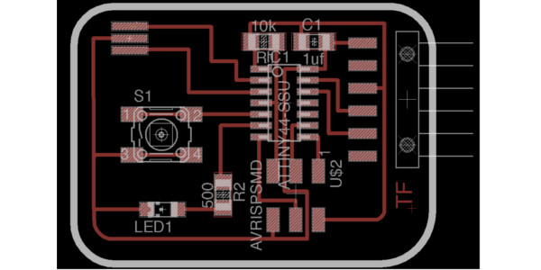
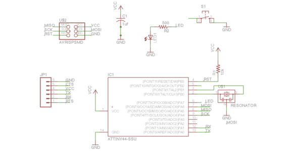
First Mistake Exporting
The first time I attempted to transfer the board layout from eagle to fab modules I made a mistake. I exported the layout correctly from eagle. I opened the copy in Inkscape to create the to png files: one for the layout and the other for the border. I exported the trace file from Inkscape and imported it into fab modules. The time it would take to make the board was over two hours, it should only tak about fifteen minutes.. I knew I made a mistake somewhere.
At first I thought is was the cut outs were used with a small tool, so I learned about the ratsnets tool in Eagle[4]. However, this was not the issue because the time did not decrease that much. It was due to a scaling issue in Inkscape, which I found after my second mistake.
Second Mistake Board Making
So next time I created the two png files in Inkscape, I thought I was all set. I scaled down the png to fit the border. Everything looked great, the time and the tool paths looked great. I started to cut the board and half way through I realized the board was small. I let the cut out continue. I took off the board and compared the board chip layout with the chip and realized I was to small this time.
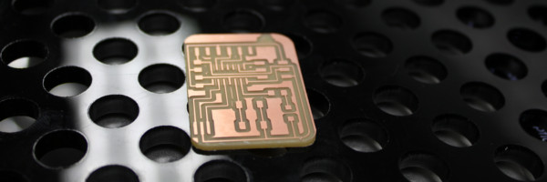
Correction
Instead of using Inkscape I used Gimp to manipulate the PNG to two separate PNG files. This worked and was able to cut the board with out any more problems.
Modify Eagle PNG file to Two Files: Trace and Border on MAC
- Import Eagel PNG.
- Save As BorderFile
- Choose Rectanlge Select Tool: Select rectangular region R.
- Select Region to darken. (Cover Traces)
- Select Bucket Fill Tool: Fill selected area with color or pattern.
- If not black.
- Click Foreground and background colors.
- In the window chose black.
- Cick in the rectangle to change color.
- You may need to do multiple times to cover the traces.
- Once complete Ctrl+Shift+E to Export.
- Repeat from 1 and Save As TraceFile to create a PNG for a trace file.
One handy tool I learned was "Windows -> Hide Docks" which hides the "Tool Box" and "Path Brushes"
Making PNG for Fab MOdules
watching Copper fill video from about 8:00 on to copper fill.
Cutout Board
I used the Roland Modela and the fab modules to mill the PCB. I used the default feeds and speeds for the different bits.
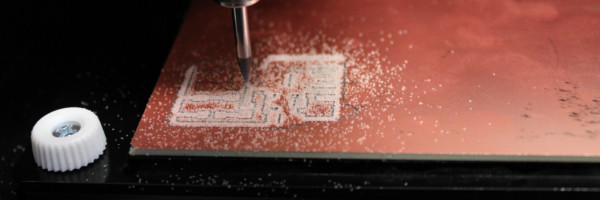
Note: I used my Linux machine, I still cannot get the MAC to work. I believe I have USB port problems.
Solder Board
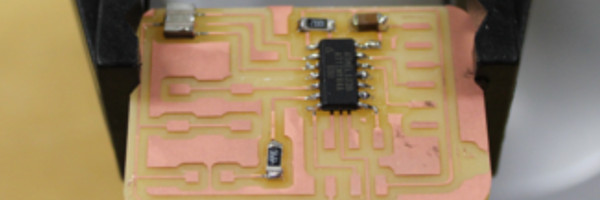
For some reason soldering this time was a little more difficult. I believe the pads were a little smaller than the previous. However, it could be that I was tired.
Test Board
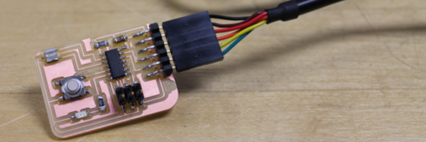
Testing the board's LED was easy with the code below writen by Adam Harris.
Click HERE for Adam's code.
Resources:
- EagleCAD tutorial (Jeremy Blum) http://www.youtube.com/watch?v=1AXwjZoyNno#aid=P8ZzOdPaT6Q
- Echo world board tutorial (Confused with the design) http://web.media.mit.edu/~liningy/sub_work/lining.yao/design%20Projects/project5.html
- Resistor data sheet - http://www.yageo.com/documents/recent/PYu-RC1206_51_RoHS_L-4.pdf
- Copper Fill in Eagle CAD - http://www.youtube.com/watch?v=4xjjahxMapc
