The Origami Folds
Concept and Plan
View My Final Presentation Poster
My final project is an application for one of my urban Architecture projects in school. The concept came from studying the surface expanding and contracting behaviour based on the user experience/need. I was inspired by the origami foldings I just had to think of a mechanism to make it respond automatically. It's an interactive covering system, will mainly act as an urban coverage system that expands and contracts and also can be used as a curtain that does the same thing automatically according to the user needs.
For detailed layout about how I planed to finish, check the Applications and implications week
This prototype Im will be working on, is to test the behaviour and the mechanism of a kinetic moving surface. It should test the technical challenges of connecting the panels together and synchronize their motion it should also test the number and the positioning of the controlling units that will have the servos and will be directly connected to the input. On a later stage after adjusting all the mechanical and electronic techtonics this project will act as a responsive kinetic surface that deals will various input forms according to the use. It can deal with potentiometer as a manual control it can deal with sensors or even stored data or sent from the web.
The Design
I started sketching the design manually and on autoCAD2013 to study the angles and how will the dimensions fit.
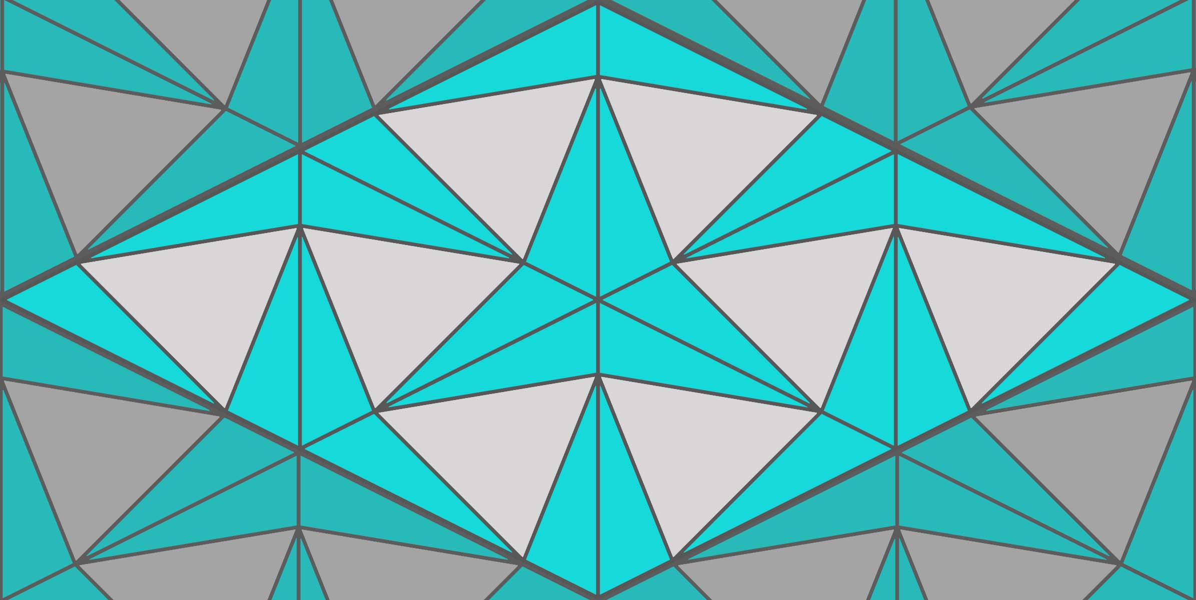
How the grid works
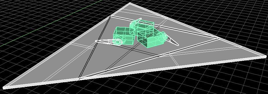
Triangles are not all equal yet each two facing each others form a module i call it couple. This couple is the real fractal of the whole surface, each four couples (8 single units) form this star which is considered to be the center of the bigger fractal (the colors in the diagram will help in illustrating the pattern)


Design files
The 3d designed unit on RHINO5
The GRASSHOPPER defenition
The Mechanism
The single unit
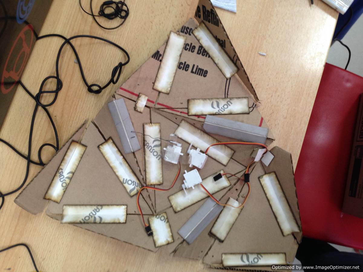
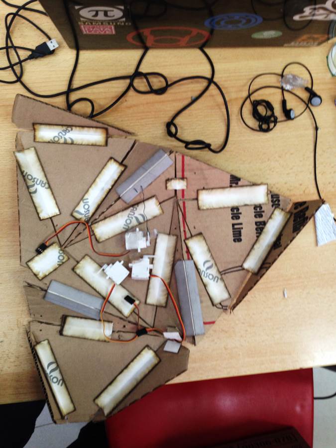
Its based on the origami grid hence it should fold and unfold equally without changing in dimension even if used for a long time. The project is divided into panels, each panel has 4 parts, three of them are right angled triangles movable and attachable to the next similar parts of the next units. while only one isoselce triangle is fixed where the servos should get fixed and supported on

The couple
This system works with synchronizing the motion of the movable parts all at once an at the same degree. The manual test I started with meant to make it as a one continues surface with only engravings that help it move up and down. But this model's scale was too small, when I tried the same way on the right scaled model it wasn't lose enough, also was very hard and heavy for the motors to move it up and down. For more details about how did th process went with the mechanism check the Mechanical Design week.
The Design files
"The surface Layout" on AutoCAD 2013
"The surface Supporders" on AutoCAD 2013
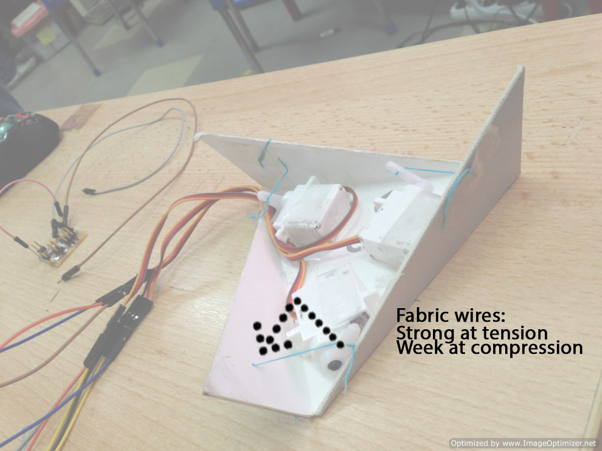

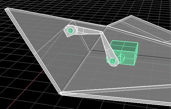
The connecting joints
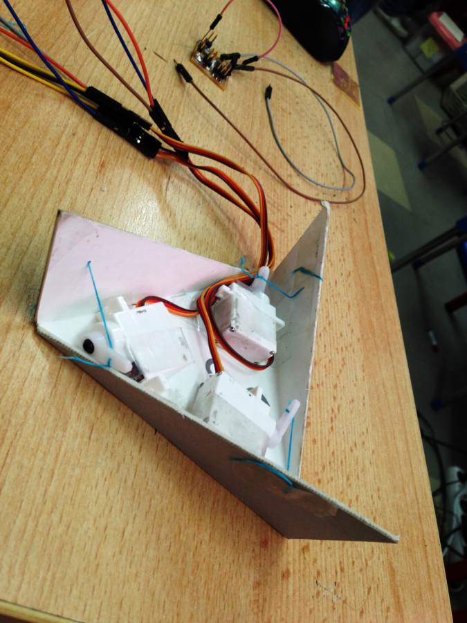
after the first test, Wires were not very good at compression as it was with the tension so I will have to change it with something more stiff. I designed this two joint arm. First joint is at the movable surface and the other is at the end of the servo arm.
Download The Design Files
Rhino5

The Electronics Design
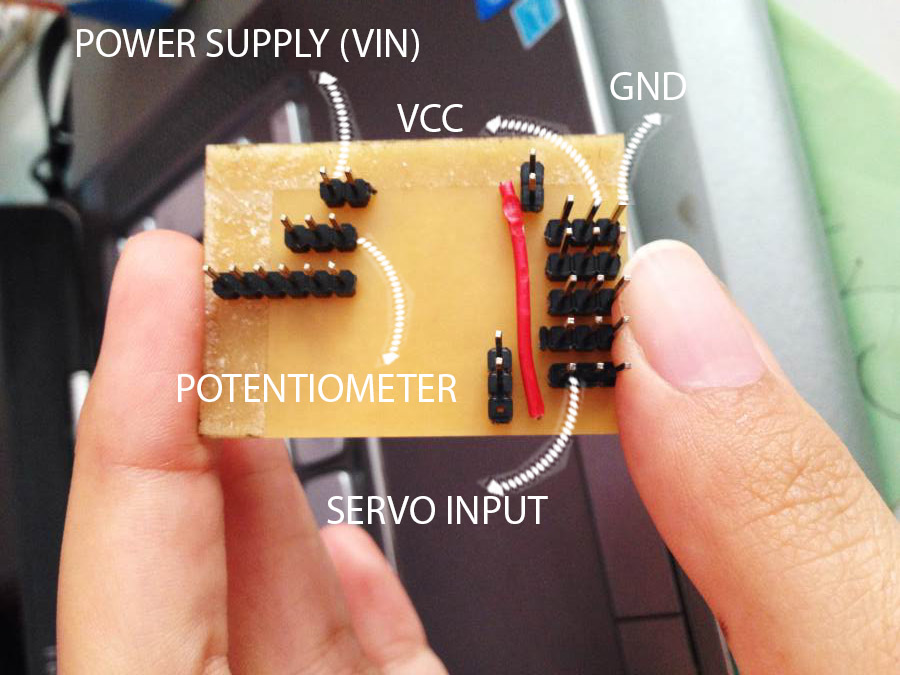
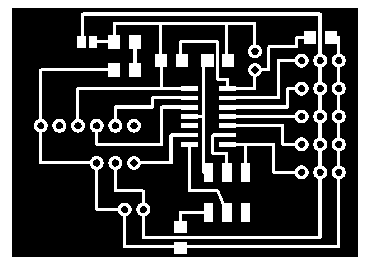
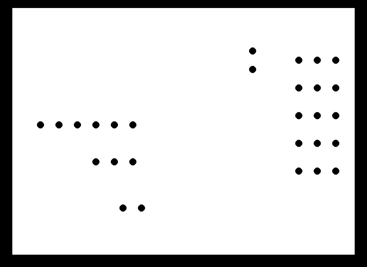
The board was designed on EAGLE and edited with photoshop. It should control 5 servos from the same microcontroller using a potentiometer as a digital input. Inspired from the hello.sevo.45 this board has
one ATTINY45
six 3pin headers (5 for the servos and one for the potentiometer)
one Capasitor
Two Resistors
Jumpers (0 ohm resistors, solder and wire connections)
one FTDI connector
one ISP 6 pin header
Design files
Schematic.SCH & Board.BRD
For more details about the process check the Inputs week and Outputs week
.JPG)
The Programing
I used arduinoIDE as a programing language the code was supposed to read from the potentiometer and send to the servos to move them at the same time. For such a connection I had to edit the library of the servos into SoftwareSerial. For more details about the process check the Inputs week and Outputs week
The Design files
Code.de
Interior.PNG
Traces.PNG
Schematic.SCH & Board.BRD

All parts together


