For the velomobile, most important mechanical parts are :
the main dimensions of Velomobile :
To model a suspension geometry, I first thought of using freecad that offers constrained sketches module.
unfortunatly, some tests on me showed the limits of this tool: the constraints do not work properly in complex systems, and the sketches are only 2D.
As for the design of the chassis and bodywork I use Blender, it is to this tool that I turn, despite the fact that it is not really a CAD tool.
it's the most exigent mechanical part of this vehicule : if it's bad designed, the velomobile will brake when turning, or can have more dansgerous reactions.
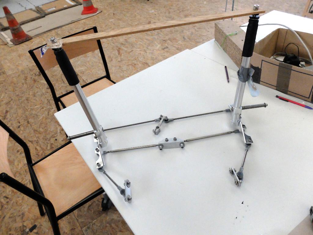
To save time and simplify the production, I bought a "Quest" velomobile front drive train.
This is a of Mc pherson front drive: This geometry is very effective and allows it to be very light, by cons it requires precise construction to function properly.
I was helped by this comprehensive resource on the geometry of a front drive.
To find the ideal positions and arm lengths, I used the constrainted sketch in Freecad
[File:TrainAV-V2.fcstd]
The quest has a width of 70cm, and, I would make a velomobile 80cm track and a slightly different wheelbase.
So I have to review the geometry particulary for ackermann correction.
So I mesure the dimensions of the train to the 3D modeling.
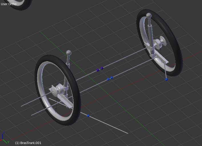
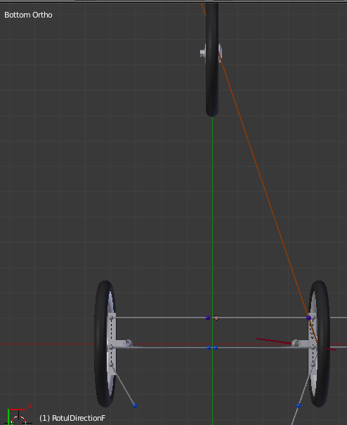
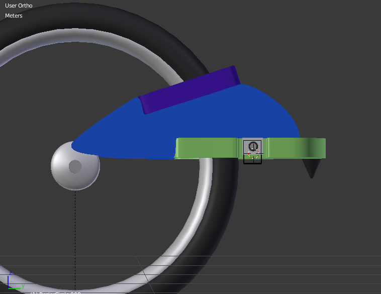
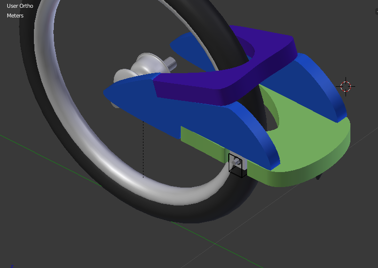
The train is attached to the frame by hinges figured in light blue and the high damping.
Red blue hinges are attached to direction command.
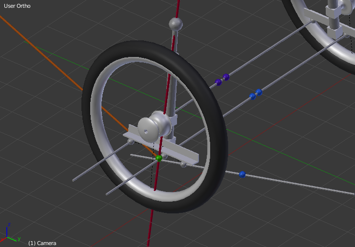
The axis of rotation of the half-axle is virtual (in red): it go between the attachment of the damper, and intersects the axes of the two rods (here extended to facilitate the alignment) in the green dot place.
To be well placed, it must touch the ground in middle of the tire (to prevent to direction being affected by braking or acceleration).
The caster angle is the angle between the vertical and the axis passing through the wheel axis and the pivot axis to the ground.
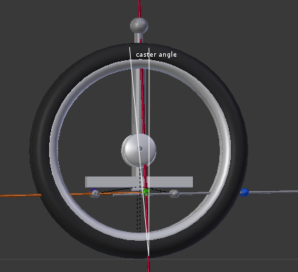
this angle must have a minimum value to ensure that the vehicle tends naturally roll straight (like a wheel cart)
If the directions rotules are exactly parallel to the wheel, turn both wheels remain parallel.
in fact, in turn, the trajectory of the vehicle passes by a tangent to the rear wheel circle.
We must shift the direction routules to correct this defect :
the exterior wheel as a turning circle larger than the interior one.
This compensation is called Ackermann , named by its inventor, it's like to the differential principe applied to the direction system
Experience shows that it is sufficient that the steering rotules crosses a line that connects the pivot axis of the front wheel and the center of the rear wheel.
In the case of a central control management (as is the case here), the offset of the steering rotules can be carried at the steering control center part.
The path string should be studied carefully to avoid disturbing the driver.
The pivot wheels shall be securely fastened because all propulsion power through them (especially the way to go: the rear wheel to bracket)
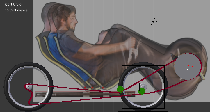
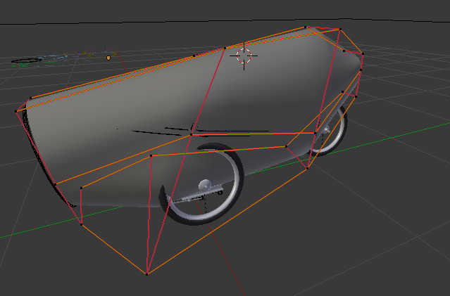
I used a background image to check the position of the pilot.
it will be built in sandwich, like the rest of the frame.
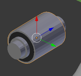
Joints will be silenblocks.
Few data to assess the size of these parts:
therefore the axial load is approximately 110 X 9.81 / 3/2 = ~ 180N
for more security, I chose a very oversized part int the Paulstra's catalog :

the reference 561004 withstand a static load of 50 daN is 500N
so I modeled briefly this silentbloc
For the suspension, I think using a conical abutment, which has the characteristic of absorbing shocks and be progressive.
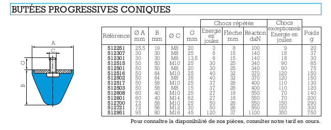
I chose the model 512503
The cone will be pressed on the frame (not modelised for the moment)
The total modelisation isn't finished.
For the moment, I decide to let the rear fork as it to go further in mainframe modeling
to be continued....
[file:trainAV.didactic.blend.zip]
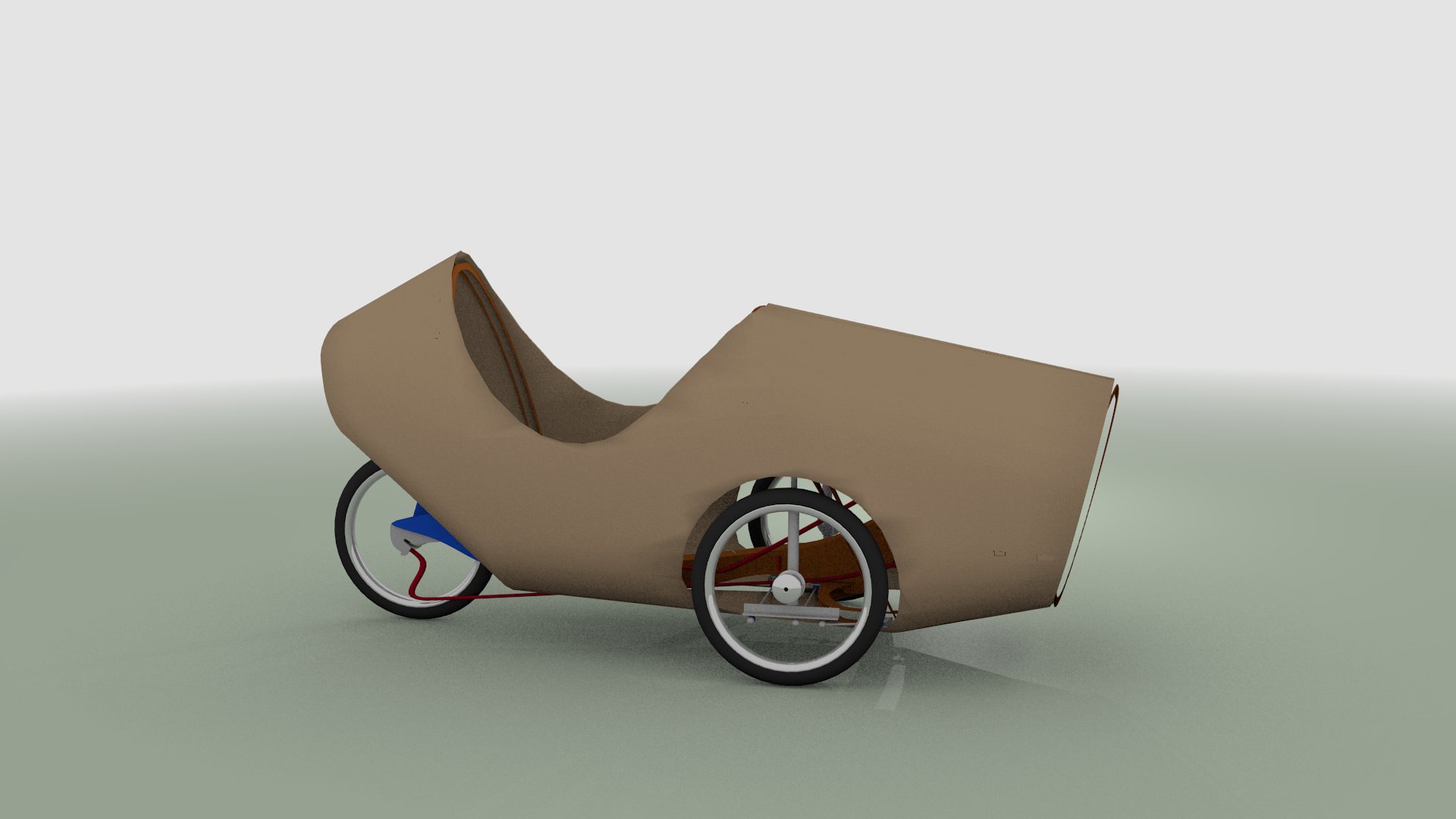
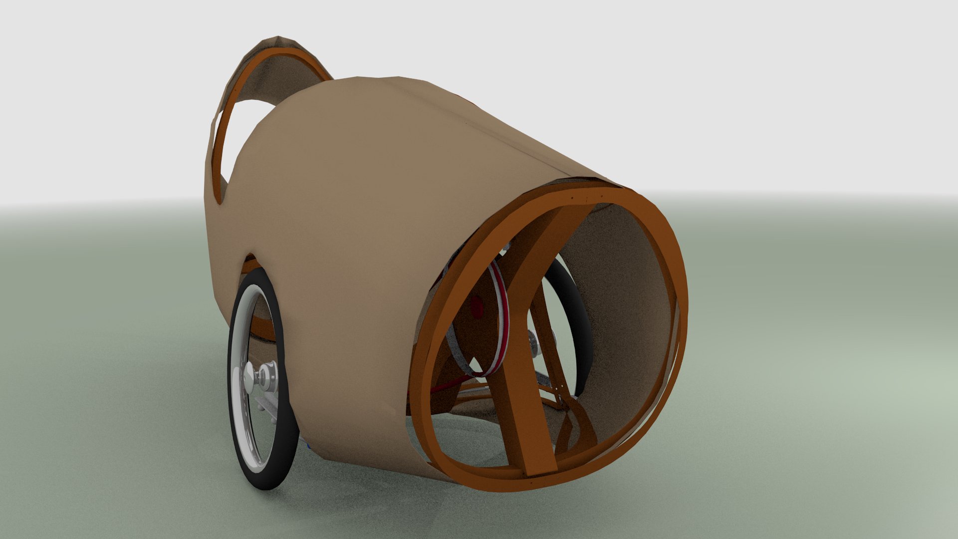
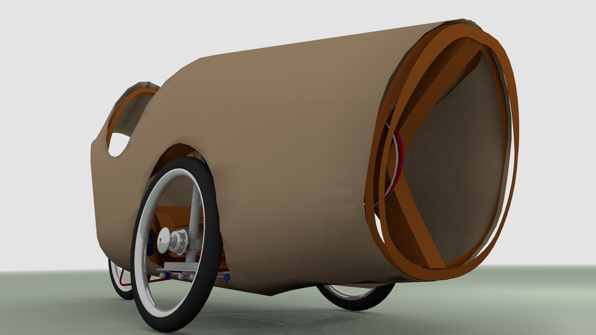
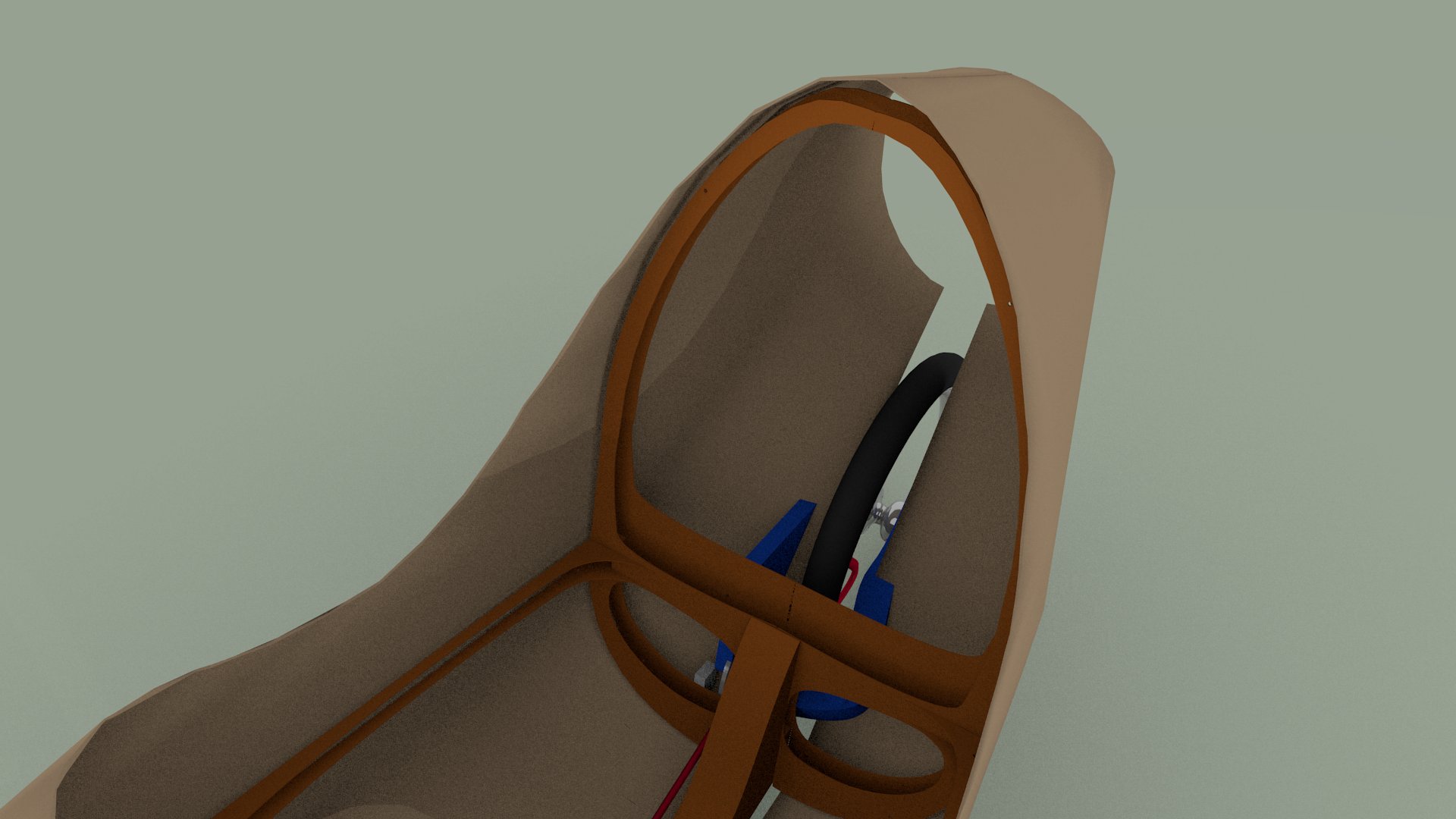
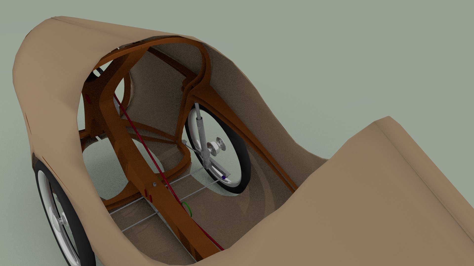
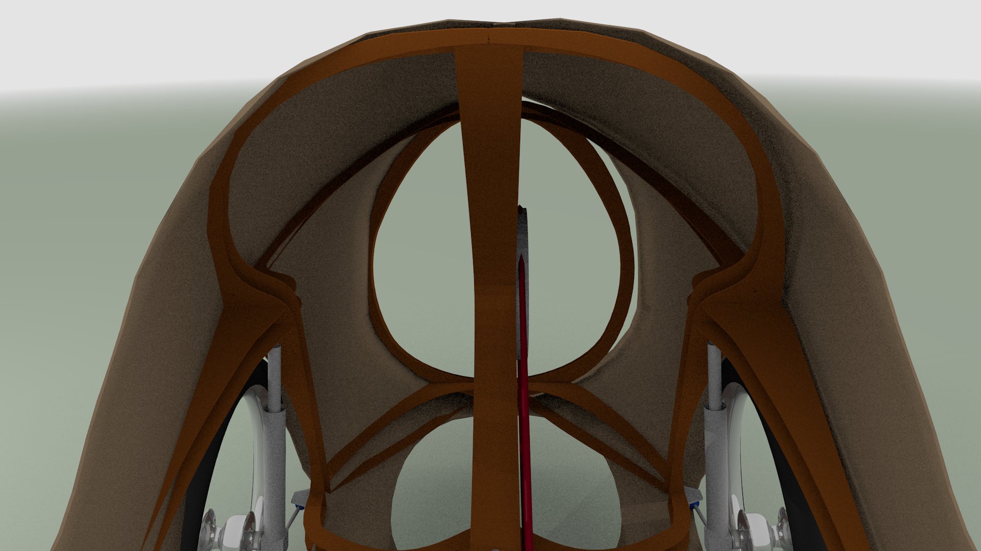
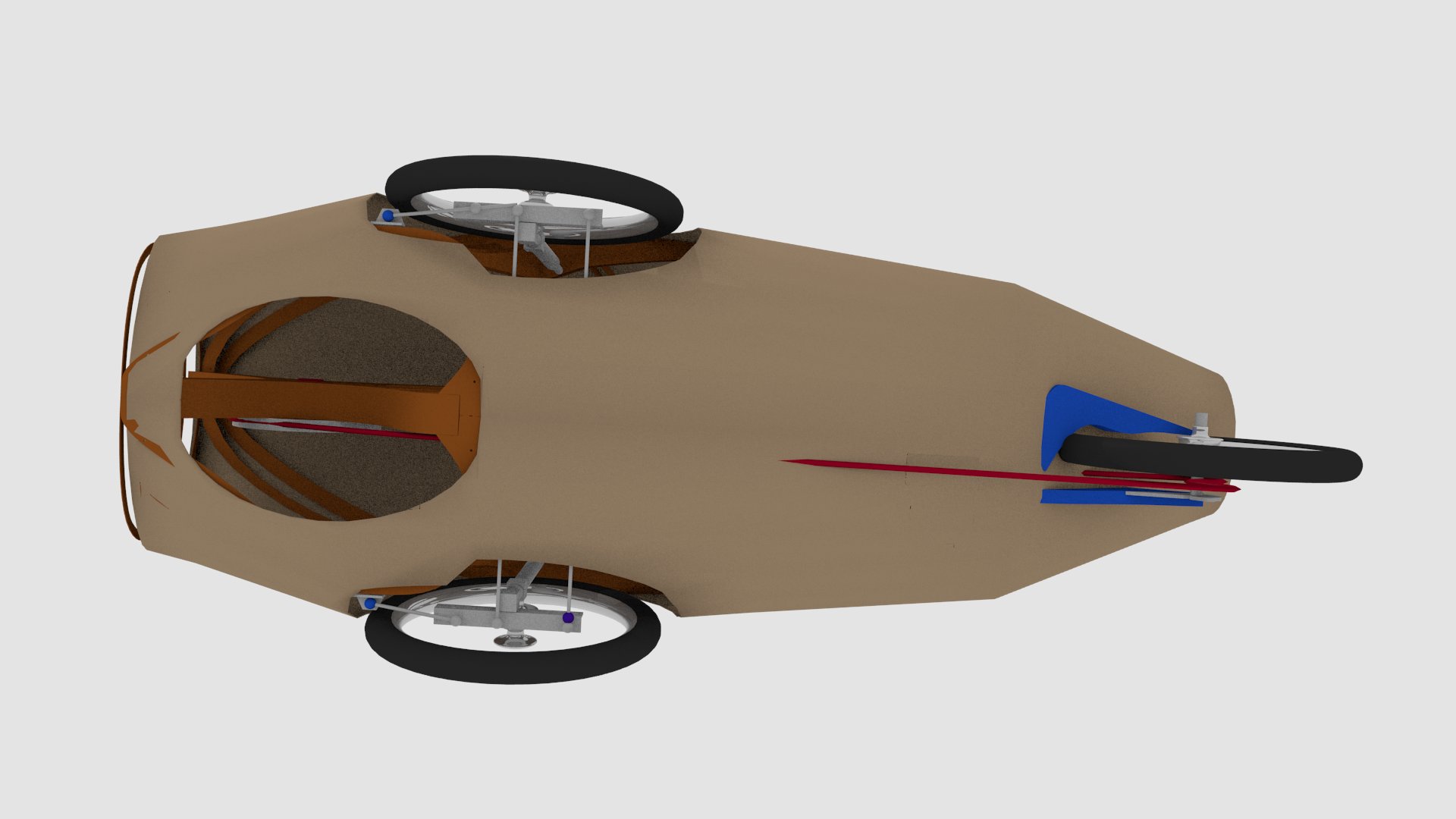
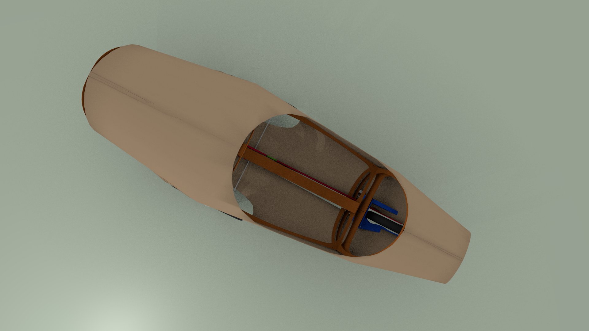
I draw finaly a relatively classical body (near like the historical alleweder)
Starting from the front drive train implantation, I tryed to solidify mecanical places, by assembly parts attached in 3 points minimum
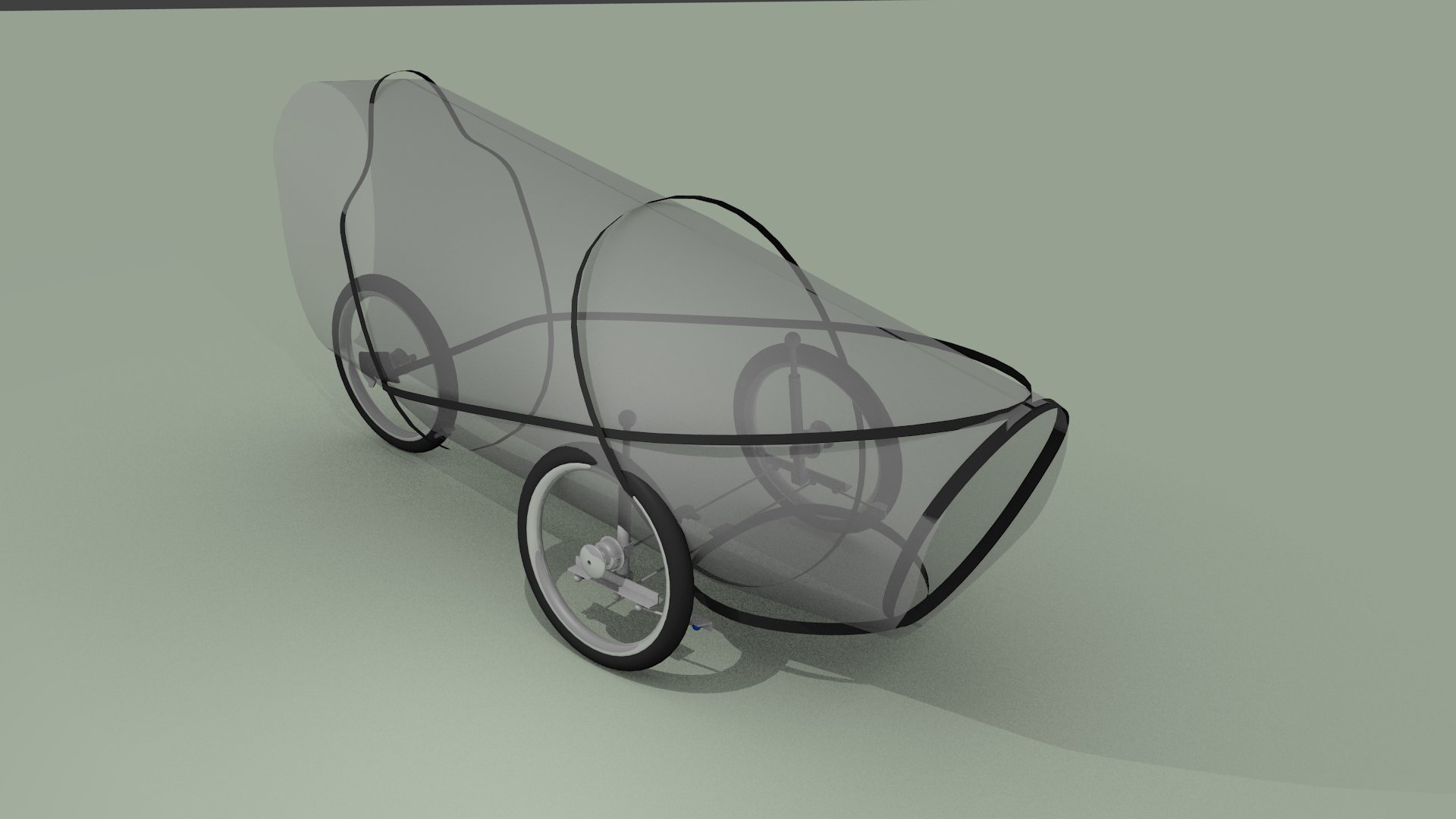
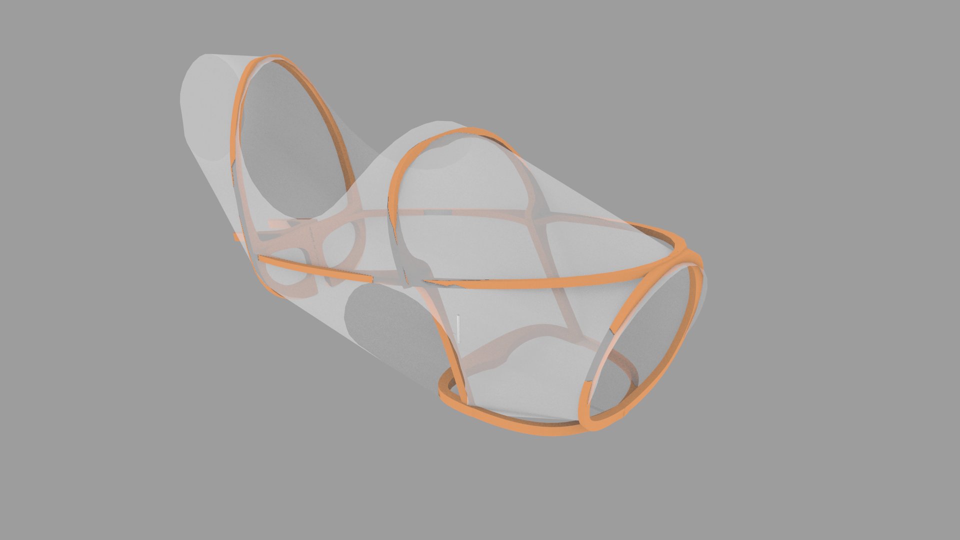
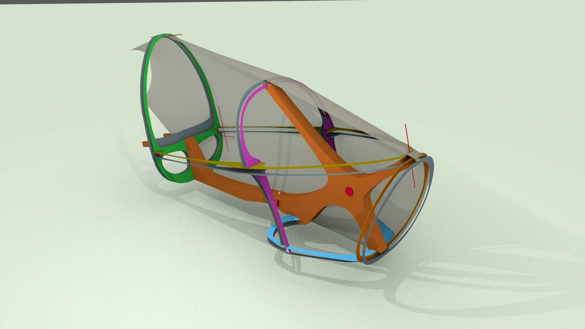
The skin will contribute to rigidity of the body.
For the modeling of it, I discover the utility of Nurbs surfaces to modelling developping surfaces
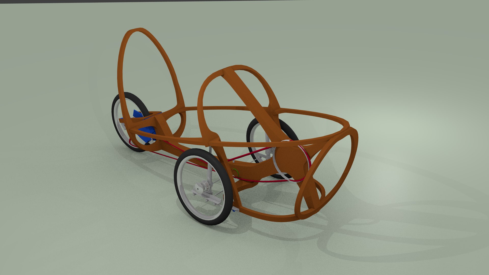
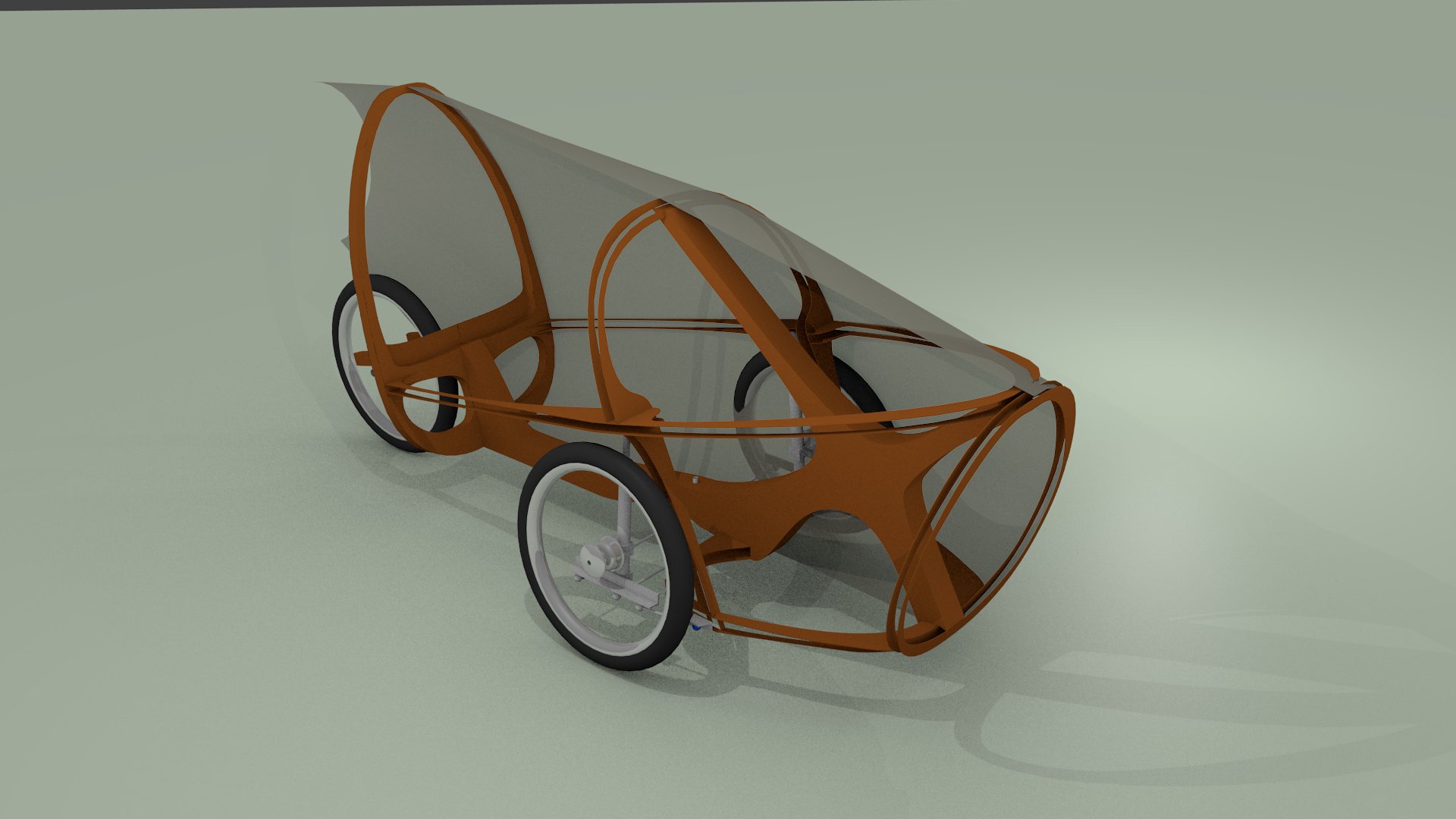
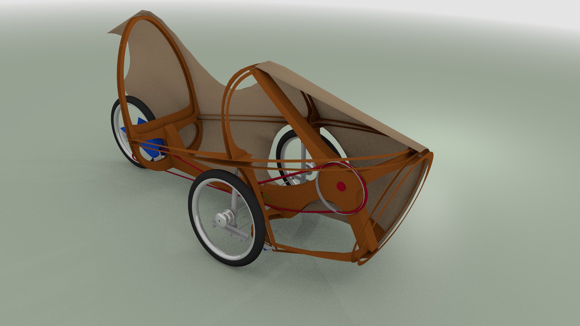
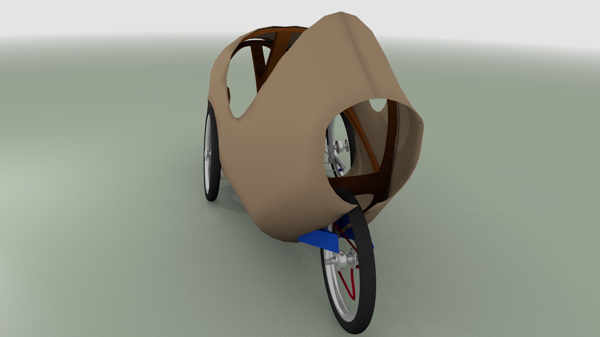
Finaly, it'seems to be a velomobile...
Later, I will add a front bulb.
I used the export SVG plugin to get nice plans from the blender file

The design is done. now follow the time of making the prototype from the blender file...
[file:Toutembois.protoZero.blend.zip]