

week 13.
This week's assignement was to...
Design and build a wired &/or wireless network connecting at least two nodes
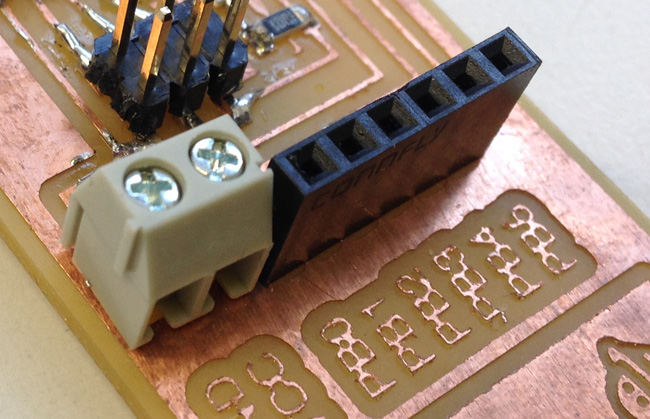
For this assignement i altered Neil's bridge board, by adding a SOCKET FEMALE 6 PIN and a TERMINAL BLOCK 2 WAY
I decided to make 2 units of the same board for the assignment, cause that way i would have too nice boards for future projects.
To make milling and cutting faster in the Modela, i prepared the pngs to mill the 2 boards at the same time. here are the pngs:


The circuit had some vias that went to the bottom of the board, so i had to do some drills. It's important to have the footprints correct, so that the SOCKET FEMALE 6 PIN and the TERMINAL BLOCK 2 WAY fit accurately, otherwise you'll have to trouble attaching the components to the board.

- - - - - - - - - - - - - - - - -
STUFFING THE BOARD
Soldering the components went rather smoothly, i'm getting used to soldering and actually starting to enjoy it, thoough sometimes it's just impossible not to curse with the frustration of not beeing able to easily control such tiny things.
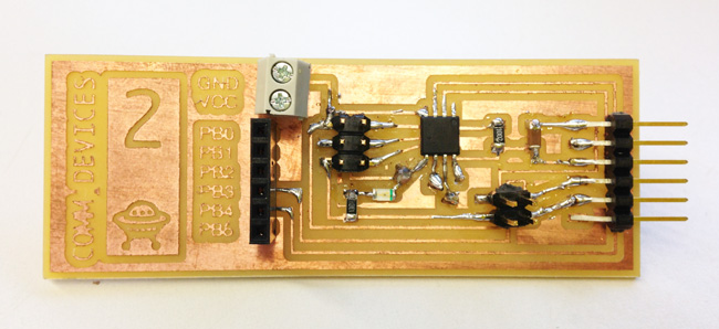

The challenging part of this task was to solder jumpers that crossed the board into the bottom, wich added some more difficulty to the task:
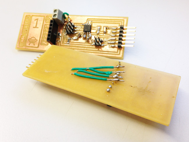
i had to solder the SOCKET and the TERMINAL
in the bottom, while holding them in place in the top of the board... and the solder was not sticking to the metal pins as easily as i expected.
Here's a detail on the bottom of the board, with the jumpers connecting to the the female socket and terminal block:
- - - - - - - - - - - - - - - - -
PROGRAMMING
As usual, i went to the AS220 tutorials for help, and with their gudiance i started this part of the assignment.
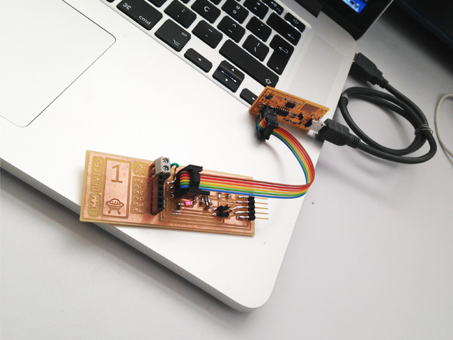
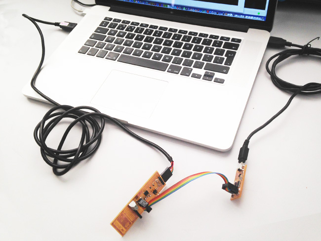
1. CONNECT:
-------- Computer to FabISP with USB-miniUSB cable
-------- FabISP to BOARD1 with flatband cable (on the 6xPIN header)
Note: when COMPUTER, FABISP and BOARD1 were connected, the red LED lightened (i don't know if it's normal that it did, but it did)
2. FLASH THE CHIP
In a serialbus, you have to determine the node number for each node. So you have to flash the each board's chip with the respective node id number (0,1,2,3,4, etc). Since I had two nodes (1x Bridge + 1x Node), i had to flash one with id="0" and the other with id="1"
Here are the steps:
-------- Download the C file and the make file at: http://academy.cba.mit.edu/content/tutorials/akf/Downloads/bus_fixed.zip
-------- Unzip bus_fixed.zip
-------- For Node 0:
- - - - - - - - - - Open hello.bus.45.c
- - - - - - - - - - Change the line #define node_id '0'
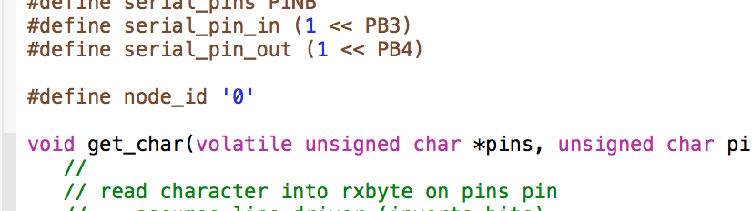
- - - - - - - - - - Save the file
- - - - - - - - - - Open Terminal and go to the folder with the C file and the make file
- - - - - - - - - - In terminal, type sudo make -f hello.bus.45.make program-usbtiny
-------- For Node 1:
- - - - - - - - - - Open hello.bus.45.c
- - - - - - - - - - Change the line #define node_id '0'

- - - - - - - - - - Save the file
- - - - - - - - - - Open Terminal and go to the folder with the C file and the make file
- - - - - - - - - - In terminal, type sudo make -f hello.bus.45.make program-usbtiny
Note: programmig wasn't working until i connected the FTDI cable. Probably beacuse it was under-powered, but i'm not sure...
Things were not showing to be running well in the terminal, with errors beeing declared, but since nothing was really working, i tried to check if the programming was somehow functioning, so i moved on to testing in Serial Monitor
3. SERIAL MONITOR
After programming, i tryed to test the functioning
-------- with PYTHON:
- - - - - - - - - - Download "term.py" at http://www.kaziunas.com/downloads/fab/term.py
- - - - - - - - - - open Terminal
execute by typing
python term.py /dev/tty.usbserial-FTGDRX66 9600
(Note: FTGDRX66 stands for the usb port where the bus connects to the computer and 9600 is the baude rate)
The monitor window opened, and this is what it showed:
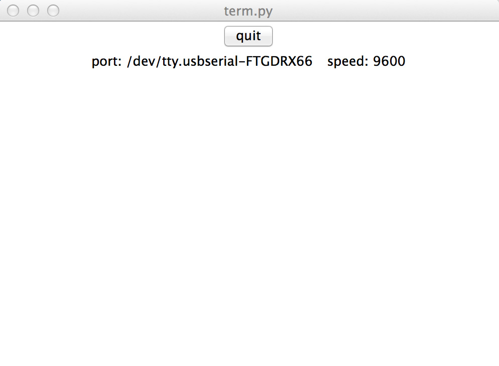
When i typed 1, or 0, it just didn´t react, and it crashed a few seconds on.
CONCLUSION
This week things went miserably bad. And the worst part is that i don't understand what happened...
You can download the design files here