I chose to focus on 2 ready-to-go projects from Shop Bot's home page (http://www.shopbottools.com/mSupport/projects.htm). I chose the drying rack because it is a simple project that involves cutting profiles. It seems like an easy beginner project and my daughter can use one of these for her apartment. I chose the Cool Cube project because it involved milling on 2 sides of a board, registering a board, and changing tools twice.
These projects seemed like a good way to build introductory skills.
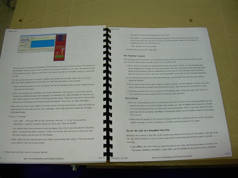
I spent several hours reviewing the ShopBot tutorials regarding drawing, layout, the computer interfaces, and examples of projects from start to finish.
One of the challenges of having a new Fab Lab is getting machines, protocols, and the like set up and ready to go. I started familiarizing myself with the ShopBot by reading the manual that came with the machine. I needed to know how to use the interface. I was also concerned about safety with a machine this large.
I started with no bit in the router and familiarized myself with controlling the mill from the keypad and using simple commands. I found the "k" command to call up the keyboard quite useful.
Early into the process I determined that the gauge for the Z zero had not been installed. I found the Z plate and installed it. This included mounting the holding bracket, running the wires and wiring the sensor into the panel (making sure that all power was disconnected from the machine!). The directions and wiring diagram in the ShopBot manual were straight forward and easy to follow. The gauge works like a charm. Don't think about using the machine without this feature installed.
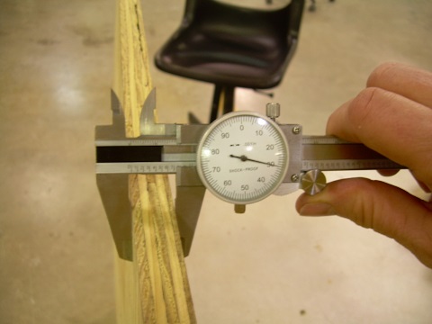
I measured the thickness of the board and determined that there was quite a range in thickness (.708 to .778). This became helpful when setting up parameters for milling.

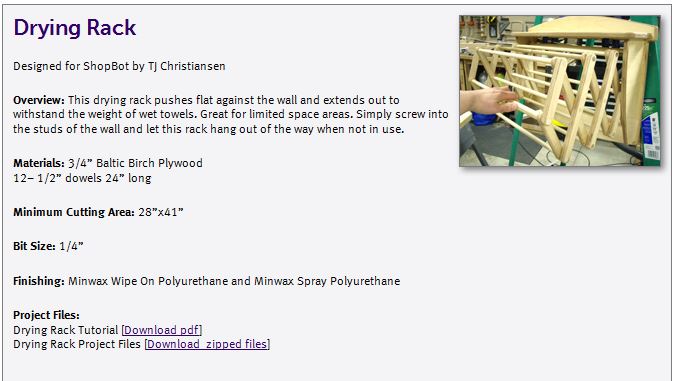
Drying Rack:
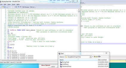
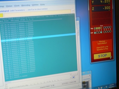
From the tutorials I was able to load the drawing files. The next step was to look at the code and determine where the zero point had been set, what clearances were in place and what the speeds and feeds had been set at. It took a while to determine that the parameters set up in the drawing program translated over to the code in the editor. I was not able to make changes in the ShopBot3 program. I came to understand that I needed to edit the drawing file or I needed to edit the code directly. I was not able to edit code from the ShopBot3 interface on the keypad when I toggled the switch to preview.
Not being able to edit in the preview mode of the milling program took some time to figure out.
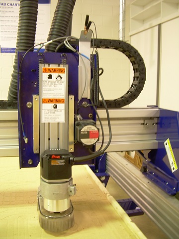
Selecting the tool and getting the machine set up was much like setting up a hand-held router. This task was easy enough.
I read the directions for setting the chip deflector guard height several times. I finally figured out the guard and the bit were the same height. It was impossible to set the machine for the thickness of the material minus 1/8 inch because the bit was not long enough to facilitate this setting.
At this point in time I began to figure out why baltic birch was called for in the project. Using lower grade lumber introduces difficulties such as gaps in the plywood, wood that splinters, non-uniform thickness, and warpage.
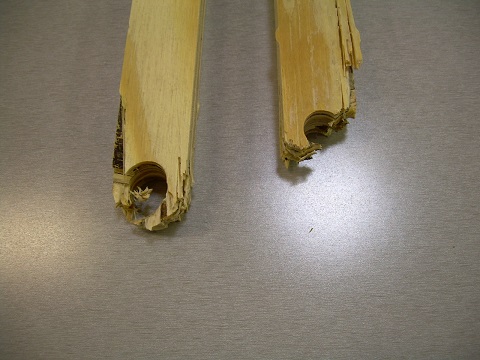
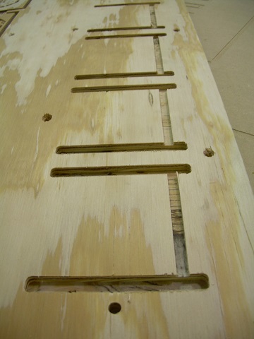
After figuring out the details the project was running smoothly. It was 3/4 of the way completed when the bit broke. Now I had to start over.
One of the things I still need to learn is how to start a program from the middle when something happens causing the operator to pause. When I moved the router table after the bit broke I moved the milling head without retaining the zeroing points on the x, y, z axis. I went to get the wrenches which necessitated the power being shut down to the mill in order to change bits. This resulted in the 0, 0, 0 coordinates being lost. I hoped that I would be able to reset the 0 points after the bit change.
When I replaced the bit I was able to get the router close to the previous zero points. It took some doing to center the bit by aligning the bit with an existing hole, finding the line of code the point corresponded to, figuring out the coordinates, zeroing the bit and then subtracting the x, y coordinates to get the actual origin.
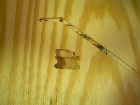
I have come to appreciate why pine and inferior lumber is not used in these products. Gaps and voids in the plywood make for a nasty finish. When the last 6 pieces were being cut the pieces came loose from the tabs and got caught in the router bit. The result was pieces that were unusable. In addition I did not get the exact origin correct when I reset the machine. The last 6 pieces had oblong holes. They weren't off by much but it is enough to make a sloppy fit.
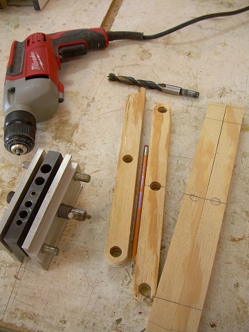
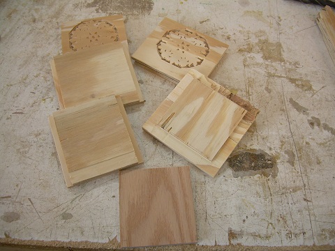
I decided to try to make spare pieces at home with a table saw, sander, doweling jig and a drill bit. Not shown are the sanders and band saw I used. I am close but not perfect with my hand made retro-fit. The two pieces match each other but not the rest of the pieces. I am also not happy with the slop that is in the rest of the pieces cut after the bit broke.
I have decided to try to edit the original drawing file. I will re-run those parts that are not accurate or that are damaged. It will take extra time but the end result will be better if I go back and try to do this correctly.
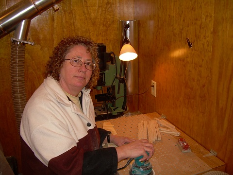
No matter how well the milling goes you still need to sand and finish.
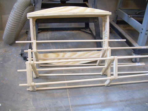
This is a rough assembly (no glue) of my drying rack. It seems to have potential. I will complete the assembly after I re-mill those damaged or mis-milled parts in order to make a quality product. The mechanism on the drying rack works and I am happy about that. The dowels will get cut to length before final assembly.
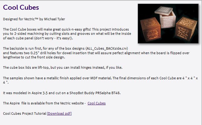
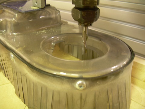
I chose the cube project because it required milling on both sides in addition to requiring 2 bit changes to complete the project. I was curious to see if I was able to complete the project given the issues I had with the drying rack project.
Before I started this project I went back to double check the speeds and feeds in the milling file. The project was posted on the ShopBot site in such a fashion that one needed to add elements to make the project work. I opened the drawing file and added hold-down screws to the project. I ran the emulator to make sure my tool path would not hit the hold-down screws. I also changed the number of passes needed to make the cuts. I slowed the feed rate down in order to avoid bit breakage.
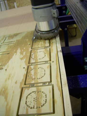
I started the project and all was going well until I flipped the board. I found a large chunk out of the back side of the plywood. I flipped the board end-for-end and started over so I had two good faces on the cube project. Once again the idea of starting with quality material was reinforced. The front of the box required milling of a pattern using a 90 degree V-bit. The bit I had access to was more on the order of a 60 degree bit. As a result the milled patterns are not as pronounced as they should be. Another lesson learned.
However, I was able to make all bit changes and retain my x, y, z origin throughout the process.
The pieces are cut out but because of warpage, board irregularities and my neglect to check the drawing against the board thickness the joints were off. The CNC mill did not router the bottom grooves deep enough, something that was not an issue on the first attempt. I attribute this to different thickness in the plywood from one side to another, warpage in the material, or better clamping in some parts over others. I ended up making final adjustments with a router table.
I sanded the individual parts before assembling them.
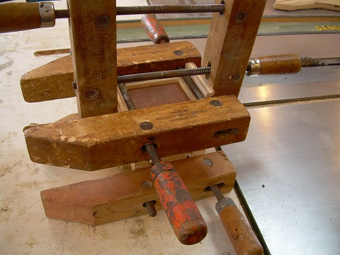
It took several clamps to glue the box together.
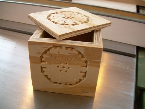
The box is complete except for the finish and final fit of the lid.
I am glad I began with smaller projects that introduced me to the overall process, tool speeds/feeds, bit types, and pre-made drawings I could edit instead of starting from scratch. I was able to concentrate on learning about editing paths and using the machine instead of concentrating on part drawing.
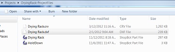
There are three different programs that are needed to run the Shopbot (ShopBot Part files, .dxf file, .crv file). The part needs to be drawn and saved or imported as a dxf file. The drawing needs to be converted to code that can be run by the CNC machine. This allows the user to edit for thicknesses of stock, zeroing points and the like.
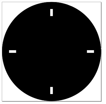


I used Inkscape to draw a three-part
table. The top is 28 inches in diameter. The
two bases are almost identical being 29 inches in total
height and approximately 25 inches wide. It will
be interesting to see if I need to double up the plywood
to get a table that is sturdy enough. I plan on
using 3/4 inch plywood that was purchased for fab lab
assignments. \
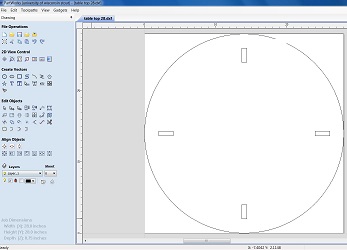
Things I learned about Inkscape was how object placement is defined. Objects drawn are referenced from the bottom left corner. Exporting objects in the proper format to be compatible with the ShopBot may prove to be a challenge.
I tried using the fab modules on the Shopbot but when the selection for Shopbot is made there is no was to provide a zero point for the mill. There are not controls for moving the Shopbot to a home position. I may try using the Modela mill feature in the fab modules to try to run the Shopbot. If this is not an option I will use the proprietary software included with the ShopBot.
Click on image to see video of CNC Router
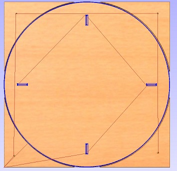
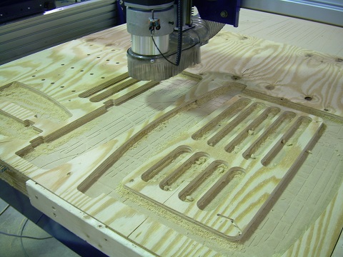
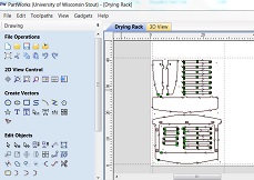
The Inkscape drawings were saved as .svg files and then imported into ShopBot software where the files were milled. Inkscape vectors needed to be heavily edited when they were imported into the ShopBot software. There were also some additional cuts that were milled that did not appear on the ShopBot drawings. I believe they were left over from the Inkscape drawings. It is helpful to make sure that all lines are drawn as, or converted to, hairlines before files are run. Toolpaths (above) were previewed before cutting.
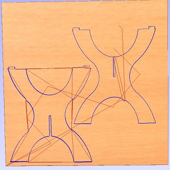
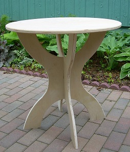
The table is a press fit table with the tabs on the top of the legs fitting snugly into the top recessed holes. There is enough overlap in the center section to provide a lot of support where the two leg sections slide together. Only one layer of plywood was needed. I used a more expensive plywood with fewer gaps and more plys than when I first started using the ShopBot. This made the project a lot more fun as there was less time used in trying to contend with holes and gaps in the material. The material also machined better leaving nicer edges. I used a router to round over the edges which gave the table a more finished appearance. There is an option to put a vinyl cut checkerboard on the top of the table so it can double as a game table. A waterproof finish will be added to make it more durable outside.
The big disadvantage of this design is that there is not an efficient use of material. With a 28 inch top, as shown here one needs a piece of plywood about 30 inches wide and 90 inches long.