|
The
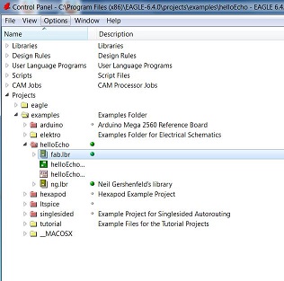
assignment started by downloading Eagle 6.4.0
software. I was able to download the software with
ease to my Windows machine with the Cygwin
interface.
I was able to use tutorials posted by Anna Kazunas France
to add the appropriate libraries and add components.
The tutorial was quite helpful.
I
tried the same download on a dual boot Windows/Ubuntu
platform logged into the Ubuntu side. I was not
successful at this attempt. The dual boot computer
seems to have died/frozen. I will be returning
that to the campus tech support and returning the loaner
computer. I will look into purchasing my own
computer and loading an older, more stable, version of
Ubuntu (version 10 perhaps?).
|
|
After some effort
I was able to get a completed circuit and stitch the nets
together.
I saved the file to continue during the next day.
When I came back to call the file up I noted that only one
of two portions had been saved. I will need to start
the process over in order to complete the exercise and
mill the boards.
As I worked through the problem I noted that it was
difficult to re-size the board to get all of the
components to fit. I would consider resizing the
board before I started adding components. There is
also the trick of adding a 0 ohm resistor to jump traces
but I did not try that.
|
|
Attempt 2 was
more successful. I was able to place components and
save the file. This time I saved both
files after placing just a few components and
then opening the file to make sure that I was using a process of saving/opening files that was
correct. I believe
my problem the first
time was that I saved
the .sch file but
got click happy and did not save
the .brd file.
|
|
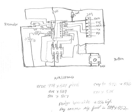
I really wanted to
understand the connections on the board and how the
components were referenced to one another relative to pin
numbers, grounds and voltages. I spent some time
hand drawing a schematic for myself that enabled me to
make the mental connection between the schematic and the
board layout. This took some time but helped me to
see how the components were connected, which pins were
connected to which devices, polarity of devices and the
like. It was worth the extra effort for me as I
understood the circuit much better after this.
|
|
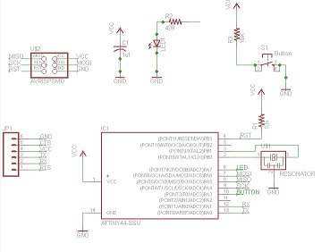
My
schematic is
complete.
I am not sure
if I need to
indicate
wire junctions
when two components
meet with a
straight wire
and no
intersection.
Anna's
tutorial indicate
that some are
and some are
not
connected.
Also, when I
go to move
components
in the board
layout view
there are multiple
traces
connected to a
component.
I have tried
deleting
and adding connecting
dots but this
does not seem
to
impact board
layouts.
|
|
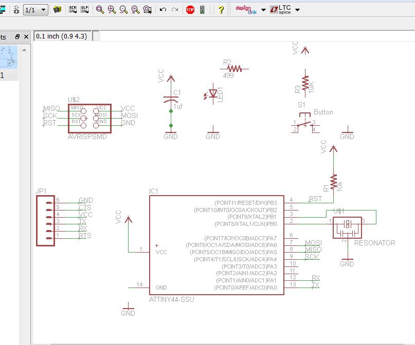
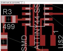
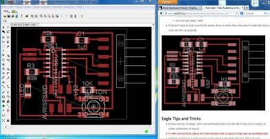
I am concerned at
how close the connections are within the board. I am
particularly concerned about the traces going underneath
the ATTINY 44-SSU chip. I took a look at the
measurements in the upper left corner and determined that
a 1/16 inch bit would in fact be able to mill out the
circuit. I also found a way to enlarge the board so
that I have more room to lay out components.
I am trying to make sure that I understand the software as
much as I am trying to conserve materials and get the most
efficient layout. I have decided to enlarge the
board in order to experiment with gaining skill in the
software.
|
|
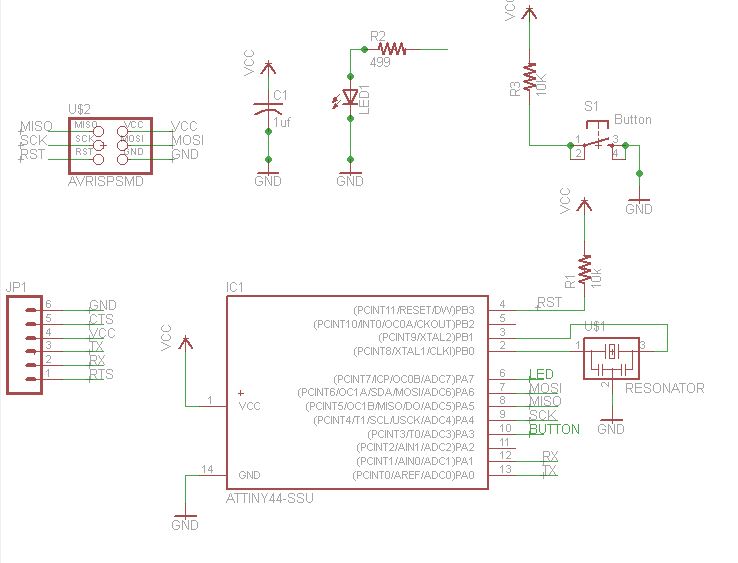
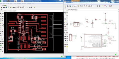
I have changed my
layout from Anna's tutorial a bit to demonstrate that I
did more than copy and paste. Some thought was given
to the layout. Differences in the LED, the 499 ohm
resistor, capacitor placement and the 10K ohm resistor on
the lower right side of the circuit are slightly different
than in the example layout on the right hand side.
|
|
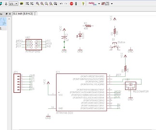
The schematic as
well as the board layout are complete. I have saved
the boards as .png files and I am ready to prepare the LED
and button board for milling.
|
|
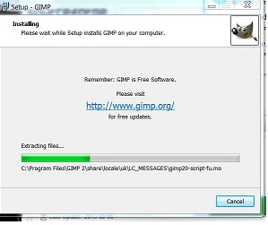
As per the
tutorial I am downloading Gimp. I am a bit nervous
about this because during the first week of class when I
was looking at software options it seemed as though Gimp
may be problematic on a Windows machine. I
downloaded Gimp without problems and was able to upload my
exported files.
I did have problems saving the files. The files
could only be exported or saved in files that were not
compatible with the mill. I used gimp to add
text. I found out when I went to mill the board that
I was not successful in making a file that milled the
exterior of the board. I cut the exterior of the
board by hand as we only had one mill and others were
waiting to use the mill. I will need to work on this
part of the process.
|
|
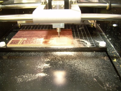
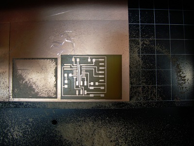
The LED and button
board have been milled successfully but not before a
considerable effort. The file uploaded fine, the
setting seemed to be correct. However, the Modela
mill would not go the
110x and 2y coordinates I specified. Abu, Scott,
Mike and I worked for a
bit over an hour on the machine. This included restarting the machine, reloading
files, and finally checking connections. We finally
discovered that our new cable linking the computer to the
Modella was defective. Very frustrating. We
had a spare cable which we used and then all worked
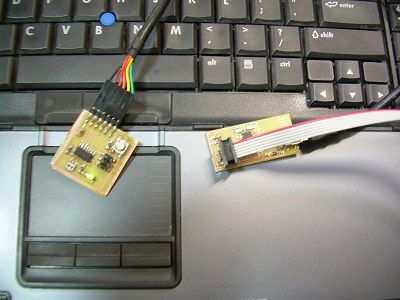
well. Note that I have placed components and solder
them in preparation for the week 8 lab. We will see
if the board works.
|
|