|
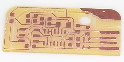
We start with a
printed circuit board. Seems easy enough. I am
working with Abu and Scott out of Century College in
Minnesota. We had trouble installing print drivers
to the Modella mill. It took a number of emails to
finally get the correct configuration to enable milling
the circuit. This was frustrating for me as I don't
know Linnux well enough to be any good at
troubleshooting. I am using two computers. The
dual boot Windows/Linnux froze up as I was trying to
complete the assignment. With the help of Anna I was
able to reinstall my folder after it became corrupted.
I spent more time trying to fix technology than
working on the technical aspects of the project.
|
|
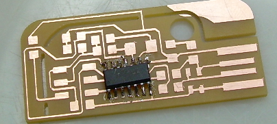
I am thankful that
I have previous electronics experience. It is
helpful in understanding what components have polarity and
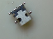
which ones do not. This is the IC1t44sm after being
soldered into place. I find it difficult to get the
components to line up while I solder them. Larger
components are much easier to place and solder but
definitely take up more space.
|
|
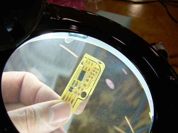
Halfway through
the soldering process I check for solder bridges.
All in all things look "OK". They are not as neat as
I would like them to be. Components aren't perfectly
straight. I am trying to follow Neil's advice and
decide if I should move on or re-solder to get the perfect
alignment. I have decided to move on to get the
project completed.
|
|
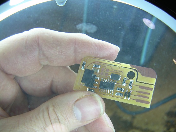
The project is
complete with the exception of 2 capacitors that need to
be ordered. The board is from Valentin's design in
the Fab Academy pages. It deviated from the list
provided by the Fab Lab so some components are
different. I am not sure if I can substitute a 10pF
capacitor for an 18pF capacitor without causing serious
ramifications to the circuit frequency.
|
|
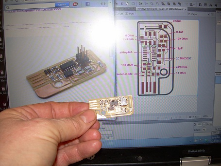
Here it is!
The schematic, Valentin's design and my circuit
board. I am almost confident it will work. I
am not sure if the 0.1uF capacitor has polarity. If
it does I have a 50% chance of being correct.
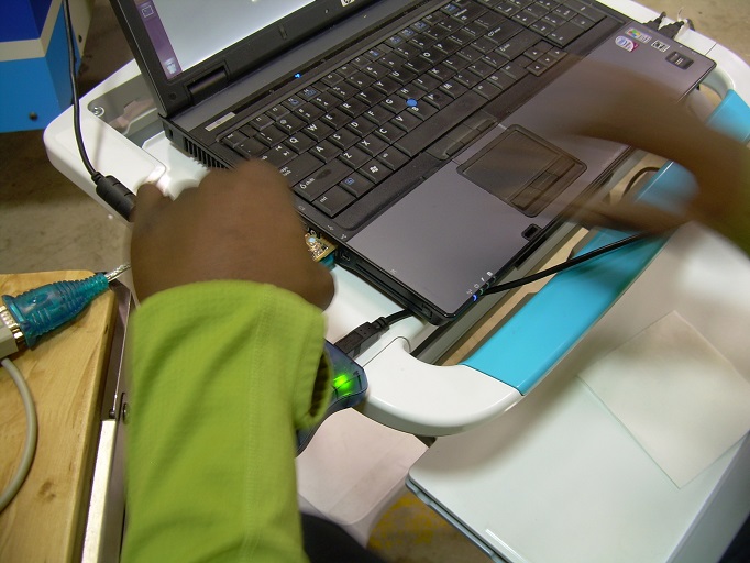
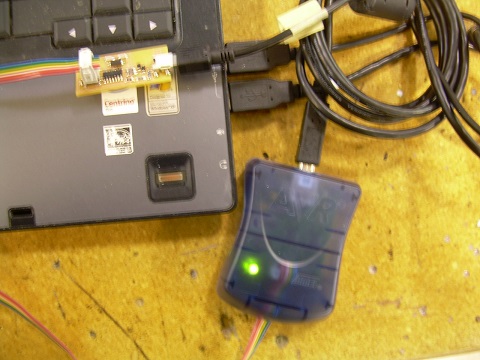
1 - 1/2 weeks later (February 23): I worked with Abu to
program the circuit board. My circuit was loose in
the USB slot so Abu showed me how to put paper on the back
of the circuit board to get a snugger fit. We ran
into programming errors and worked with Anna and Blair to
get them resolved. We made some progress after
downloading the Macintosh version of the code used.
There were still errors and there may be 2 issues.
1) We did not have 18 pF capacitors on hand and we used
10pF instead. 2) Traces are too thin from when we
first manufactured the board. We ran a voltage check
and everything seemed fine but?? 3) There is a
flawed design or some other issue we are not seeing.
4) The USB port may not be making a good enough
connection. 5) There are flaws in the circuit as
build and/or designed.
This has been a very frustrating project with progress
coming slowly relative to getting the board
completed. We may try making one one of the
different designs to see if we can get a different design
to work.
|
|
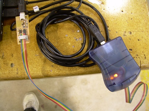
Friday, March 1st:
Abu, Scott and I are trying to program our
FabISPs. We are not able to get the computer to read
the connections on the circuit board. We have tried
different computers and different USB ports. No
luck.
|
|
We continue to troubleshoot circuits by testing for
voltage drops. No luck.
|

|
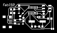
I have decided to
make the circuit board that is listed in Anna Kaziunas'
tutorial. I download the circuit board and mill
it. I solder all of the connections and test the
board. It doesn't work at first but after I resolder
the USB connections --- It works! Yay! I am
quite excited and relieved. Abu helps me program the
board and I feel like I have made quite a bit of progress.
|
|
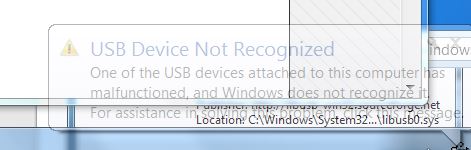
March 8:
Disappointment!! I am ready to proceed with the next
electronics project. I find that my Fab ISP is no
longer recognized by the computer. I try different
computers and find that my ISP works intermittently.
There is a connection loose somewhere in the USB
connector. It is time to get serious.
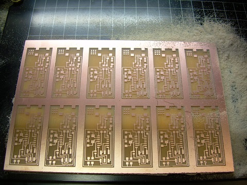
March 13: I mill out 12 Fab ISP boards using Anna's
design. I got the circuit to work once so I am
confident I can do it again. I figure I may as well
mill a number of boards. You never know how many
tries this will take. The 12 circuit boards take
several hours to mill as I move between other tasks.
|
|
I try a technique
to solder the mini USB. I turn the USB over and
attach a small amount of solder to the underside of the
leads. When I turn the component over and set it on
the board it is easy enough to get the component neatly
soldered onto the circuit board. All is going well
with the second board.
I continue to solder and the board looks good. So
far, so good.
|
|
With the circuit
board completed I continue on with installing the software
needed to complete the project. The last time I
programmed the Fab ISP I used the computer in the
lab. I am working to make sure that I can complete
all facets of the project so I am interested in getting
the software side of things to work as well.
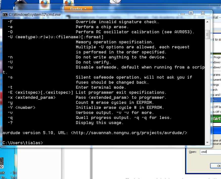
The last time I tried to download and run AVRdude I was
unsuccessful. I make sure the files have been
unzipped/extracted. I check to make sure that
program are showing up on the C drive when
necessary. I have also created a special folder for
the Fab downloads on my computer as per Blair's
suggestion. This makes things easier. I am
successful on this second try.
|
|
WinVR has
installed and again there is no problem. Things are
progressing smoothly.
|
|
With drivers
installed I check to see if my new ISP is being read by
the USB port. Success! 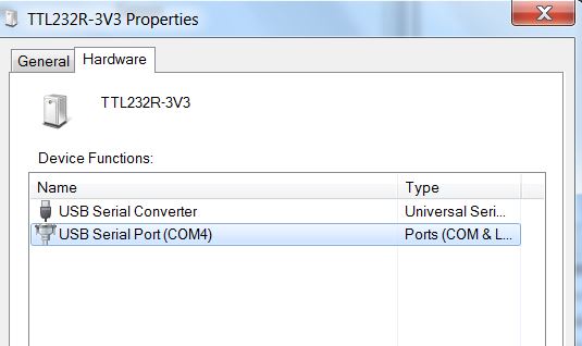 |
|
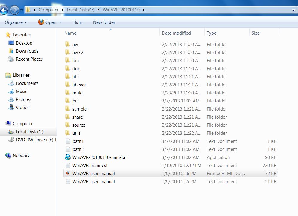
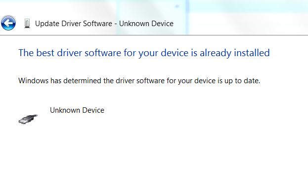
I work to install
the drivers as per Anna's instructions. Once again I
have achieved some level as success as shown by the screen
shot. I have installed the necessary drivers to make the
ISP work. 
|
|
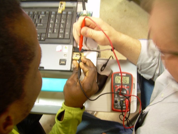
I hook up the Fab
ISP only to find that the programming will not work due to
bad connections somewhere. A visual inspection
provides no clues. The solder joints look
good. I review Anna's tutorials and find that the
problem may be the 6 pin connector. I use a
multimeter to do a connectivity test. I have
continuity between pins 1, 2 and 6.
After several attempts, burning up a trace to pin 5 and
repairing with a jumper, I try again.
|
|
Success at
last. I am ready to program my Fab ISP. The
problem was too much solder on the 6 pin connector.
I used copper braid to remove solder and tested with the
continuity tester. With no connections between pins
I am ready to continue programming the Fab ISP.
|