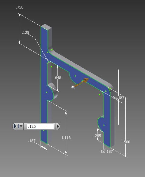
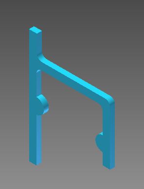
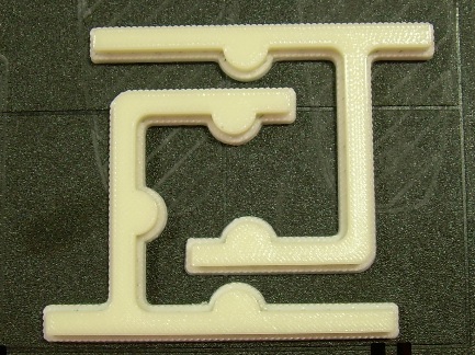
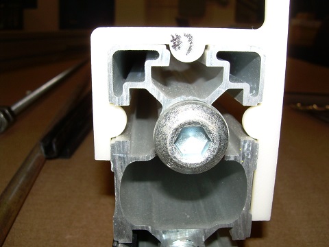
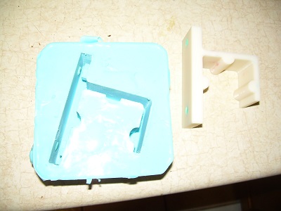
I followed his advise and the technique worked. We will need to drill the through holes for the bolts separately. This should be an easy enough task as I left recesses for drilling locations as part of the molding process.
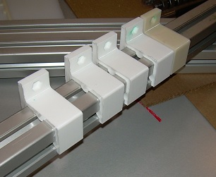
The parts can be removed from the mold after about 20 minutes but it takes longer for them to reach full strength and rigidity.
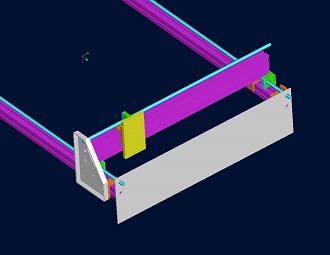
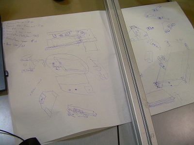
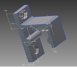
Mike is working on drawing and redrawing components. He is verifying that the machine will work on ProE. He deleted the spacers for the bearings. There wasn't enough room for the nuts that go with the screws, so he moved the screws above the rails. An alternative option is to put the 'long screws' on the outside of the 'side plates'.
Things that Mike identifies as
needing attention includes:
1. Needs a name.
2. Need to know which pulleys/belt is going to be
used. The motor mounting patterns need to be sized
correctly.
3. Need to know which motor is going to be used.
Need dimensions of mounting hole pattern and boss by
shaft end if there is one. Datasheet dimensions
seem incorrect.
4. With a little bit more info, I will cut / form the
side plates and end plates.
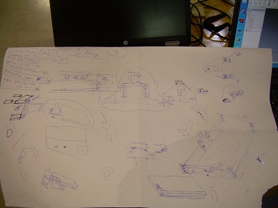
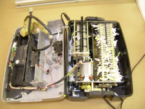
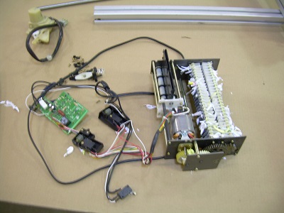
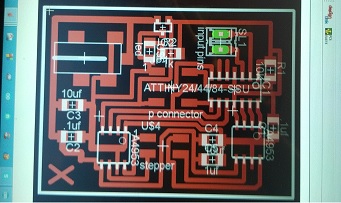
We are also trying to figure out the electronic system. We can fall back on Arduino or a computer with LinuxCNC or go all the way back to windows using Mach3.
//STEPPER MOTOR DRIVING PROGRAM
//MOTOR 4209L-03-01
//INPUT pin definition
//for step
int stepForward = PB0;
//for direction
int stepBackward = PB1;
//OUTPUT pin definition
int stepperPins[] = {PA0,PA1,PA3,PA4};
//initialize the constant
int znum = 1;
void setup(){
//OUTPUT pin setting
for(int i=0;i < 4;i++){
pinMode(stepperPins[i], OUTPUT);
}
//INPUT pin setting
pinMode(stepForward,INPUT);
pinMode(stepBackward,INPUT);
}
void loop(){
if(digitalRead(stepForward) == HIGH){
switch(znum){
case 1:
//STEP4
digitalWrite(stepperPins[0], LOW);
digitalWrite(stepperPins[1], HIGH);
digitalWrite(stepperPins[2], HIGH);
digitalWrite(stepperPins[3], LOW);
znum = 2;
break;
case 2:
//STEP3
digitalWrite(stepperPins[0], LOW);
digitalWrite(stepperPins[1], HIGH);
digitalWrite(stepperPins[2], LOW);
digitalWrite(stepperPins[3], HIGH);
znum = 3;
break;
case 3:
//STEP2
digitalWrite(stepperPins[0], HIGH);
digitalWrite(stepperPins[1], LOW);
digitalWrite(stepperPins[2], LOW);
digitalWrite(stepperPins[3], HIGH);
znum = 4;
break;
case 4:
//STEP1
digitalWrite(stepperPins[0], HIGH);
digitalWrite(stepperPins[1], LOW);
digitalWrite(stepperPins[2], HIGH);
digitalWrite(stepperPins[3], LOW);
znum = 1;
break;
}
}
if(digitalRead(stepBackward) == HIGH){
switch(znum){
case 1:
//STEP1
digitalWrite(stepperPins[0], HIGH);
digitalWrite(stepperPins[1], LOW);
digitalWrite(stepperPins[2], HIGH);
digitalWrite(stepperPins[3], LOW);
znum = 2;
break;
case 2:
//STEP2
digitalWrite(stepperPins[0], HIGH);
digitalWrite(stepperPins[1], LOW);
digitalWrite(stepperPins[2], LOW);
digitalWrite(stepperPins[3], HIGH);
znum = 3;
break;
case 3:
//STEP3
digitalWrite(stepperPins[0], LOW);
digitalWrite(stepperPins[1], HIGH);
digitalWrite(stepperPins[2], LOW);
digitalWrite(stepperPins[3], HIGH);
znum = 4;
break;
case 4:
Stepper control program is as follows:
/* Stepper Bipolar
*/
int motorPins[] = {PA0, PA1, PA3, PA4}; // pin numbers in order of 13,12,10,9
int frontPin = digitalRead(PB0); //
int backPin = digitalRead(PB1); //
int count = 0;
int count2 = 0;
int delayTime = 500;
void setup() {
pinMode(frontPin, INPUT);
pinMode(backPin, INPUT);
for (count = 0; count < 4; count++) {
pinMode(motorPins[count], OUTPUT);
}
}
void moveForward() {
if ((count2 == 0) || (count2 == 1)) {
count2 = 16;
}
count2>>=1;
for (count = 3; count >= 0; count--) {
digitalWrite(motorPins[count], count2>>count&0x01);
}
delay(delayTime);
}
void moveBackward() {
if ((count2 == 0) || (count2 == 1)) {
count2 = 16;
}
count2>>=1;
for (count = 3; count >= 0; count--) {
digitalWrite(motorPins[3 - count], count2>>count&0x01);
}
delay(delayTime);
}
void loop() {
if (frontPin == HIGH)
moveForward();
else {
delayTime = 1024;
}
if (backPin == HIGH)
moveBackward();
else {
delayTime = 1024;
}
}