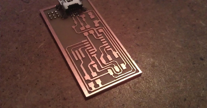
This week I didn't worked on my final project but I performed the homework assignment. First I slightly edited fab_isp programer png file using GIMP to make board look more accurate:
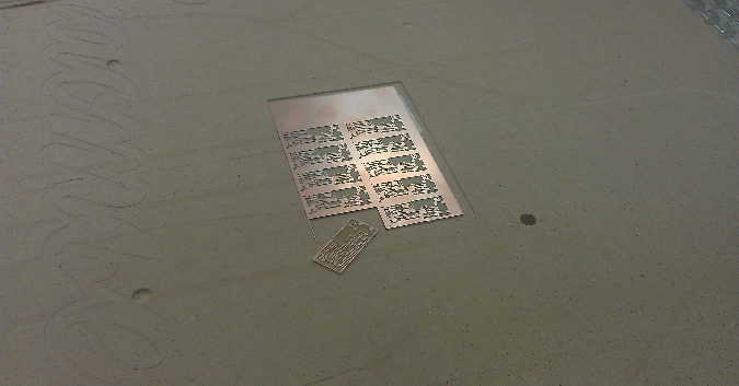
Then Dmitry Latkin made a pack of them using FlexiCAM:
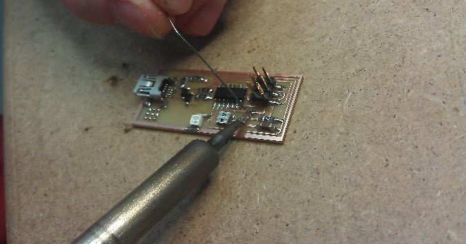
Assembling these boards is quite easy. Here is a photo which I took during the process:
Anyway, some tips which could be helpful:
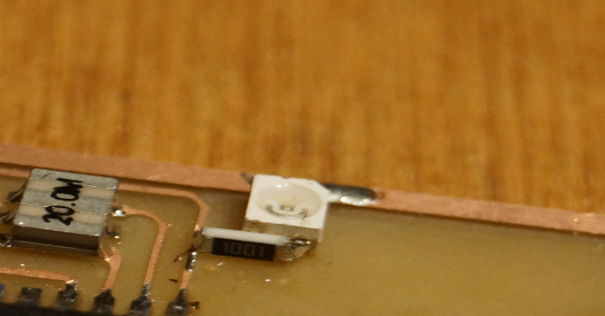
Additionally you could solder and LED + 100-Ohm resistor to indicate power supply. I have done it like this:
The last thing is to solder jumpers to set the board in the so-called "firmware update" mode. For SJ2 you should use a 0-Ohm resistor but SJ1 could be connected just with a piece of solder:
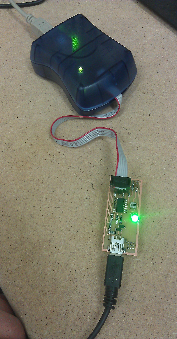
Now it's time to upload the firmware. For that I used AVR ISP mkII programer which is presented in Fab Lab inventory by default. Connect the 6-pin ISP cable to the board like this:
And then plug both USB cables into your PC running Ubuntu. Download firmware from official Week 4 page: firmware.zip
Then unzip it into any folder. Uploading firmware is extremely easy - open terminal, cd to firmware directory and then run this magic command (root password required):
make clean && make hex && sudo make fuse && sudo make program
If you've done everything 100% fine you should get message like this:
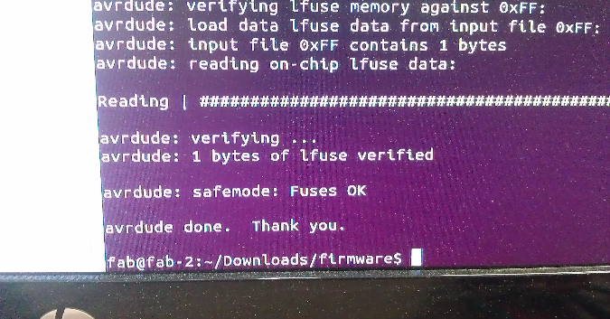
Now unplug everything, desolder SJ1 and SJ2 (braid might be helpful) and PC should see your own DIY in-system-programmer just like the AVR ISP mkII!
Job done! To make sure that there is no functional difference between two programmers you should make an ISP cable with 2x3 2.54 pitch connectors.