This week we had to add an output device to a microcontroller board and program it to do something. I chose to add an LED Array to a board using an AtTiny44 microcontroller.
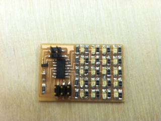
The first thing that I did this week was to mill out the hello.array.44 board from the class website. After milling, I soldered the necessary components onto the board.
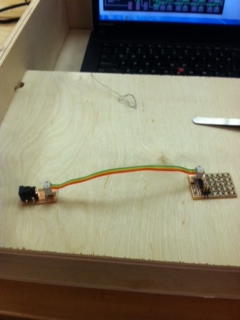
After I milled the board, I then had to mill and solder another board to be used as an external power supply for my board. I connected the two using a 4-pin connector.
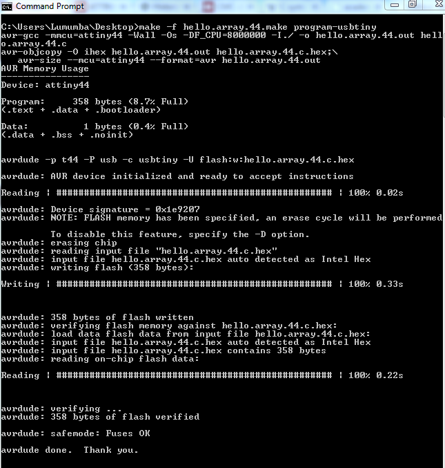
I then programmed the board using my fab.isp programmer and the make and c files from the class website for the LED Array board.
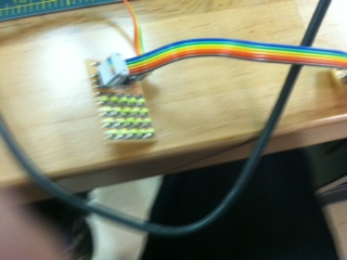
Once I programmed the board, I was able to see the lights flashing.
Once I knew everything worked properly, it was time for me to try to make it do something interesting! I first started out by making a chart that mapped the variables in the code with the LEDs that they represented.
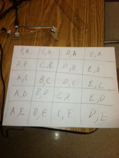
Once I knew the exact correlation between the code and where each LED was, I able to work with another student to determine which LEDs would produce particular letters. We then made a list of which variables in the code corresponded to portraying particular letters on the LED Array.
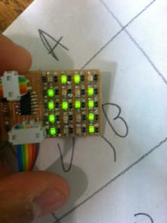
Once we established which code variables should create letters, I tested an "A" on my board. It worked!
After the "A" worked, I decided to put words together with a random sequence in between words to represent a "space". Here is the code that I modified from the original C file.
And here is the video of what my board actually does! Use sound if you want to hear the end.