Fab Lab Barcelona SuperNode /Fab Lab Sevilla /Jose Perez de Lama
Week 13 / output devices / 17.04.2013
[assigment]
Add an output device to a microcontroller board and program it to do something.
Class syllabus::
http://academy.cba.mit.edu/classes/output_devices/index.html
[what i learned /am learning]
_ Relearned Arduino installation.
_ Work with DC motors and H-Bridge IC with Arduino; and its general concepts.
_ About the various Fab versions of Arduino and their features and differences: hello.arduino, fabkit2.0/fabduino, barduino.
_ How to make and program the hello.H.bridge.44 board to use a DC motor.
_ Started learning how to make and program my own version of Arduino: hello.arduino and fabduino.
_ Related to the past weeks, eventually! i learned what high byte and low byte mean. I had been quite confused with this, because High and Low, mean of course different things depending on context. I found the answer in the Arduino Cookbook, p:85, that Tomas Díez once recommended: If we consider a byte / 8 bits; the low byte are the four first [right to left] bits/digits, and the low byte are the second four bits/digits. Sometimes, as in our use of serial communication, it is convenient to break the bits in two parts. Then you usually need to put them together again. All this we have been finding in the C and Python scripts that we have been using; but i didn't understand it until now. A start bit and a stop bit have to be put in front and at the end to tell the computer how to interpret the data.
[preliminary comment]
Starting to work in the assigment, i realized we were missing in our local inventroy a part that was needed in all of the hello boards proposed for this week, which is the regulator. So i ordered them at digikeys together with some other materials that we will be needing soon. In the meanwhile we started working on one hand studying the boards, milling and stuffing them, and on the other working with arduino, and preparing our own arduinos at the lab to fabricate. Thanks to Luciano [Barcelona / barduino], Nuria and Ruben [fabduino / León], for their great help, as well as, of course, to all the preceding htmaa and Academy students for their tremendous projects and documentation.
I have to mention, i like enormously the Arduino project. I consider it one of the most amazing things that has happened in the field of knowledge and production in the last decade. I might say that i had met David Cuartielles, one of the project leaders before he started in the project, and were using a server of him for some years in an independent media project that became quite relevant.
I think that from now on we will try to work on two lines in electronics; on one hand we will make and test the Fab Academy prototypes, and on the other we will rely more on self-made-arduinos for the final project, as it seems easier for beginners; and also more accessible to work with in the future. We will see...
[assignment development]
[preparing, milling and stuffing the boards]
For the assignment i wanted to use a board with the H-Bridge IC that professor Gershenfeld had praised in the class. The H_bridge allows to control higher-demanding device such as a DC or stepper motor, with the 5/3.3V and ca. 40mA supplied by the hello board [or the Arduino].
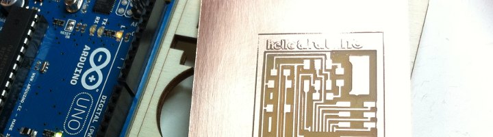
So i chose the first DC motor board - hello.H.bridge.44 -. I most probably will use motors for my final project, and this seems to be like a good starting point. To find out about some not so clear board components, i checked the .cad file, that indeed gives some info about it:
IC2 = regulator_SOT23('IC2\n5V')
Double
checking
the fab inventory, as mentioned, that it should be "IC
5.0 100MA LDO
VREG SOT23" digikey ref. LM3480IM3-5.0/NOPBCT-ND -
and i
realized with some
dissapointment we don't have them, and as mentioned, i
ordered them,
but still went on preparing the board. The other
components we have
already used in previous assigments, so that feel
familiar.
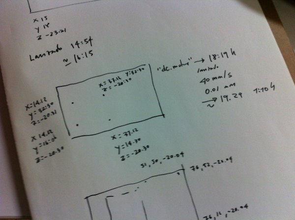 Planarity
calibration notes for
the iModela
Planarity
calibration notes for
the iModela
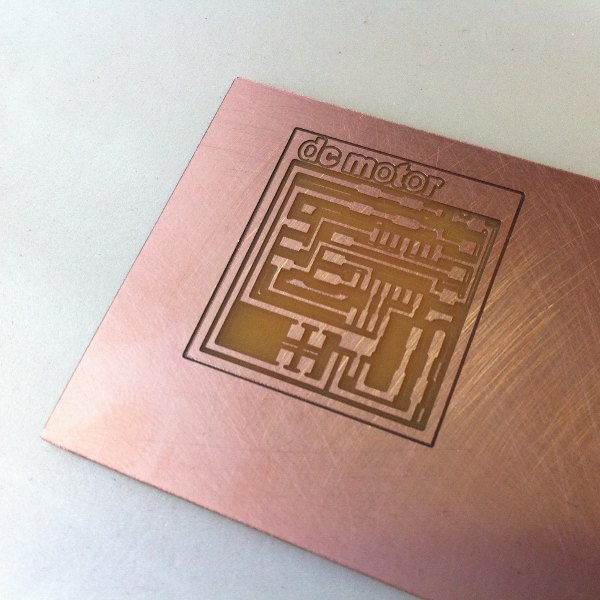
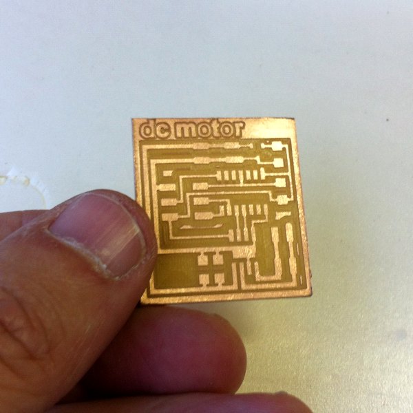
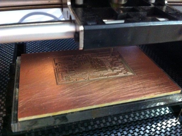
It might be not so easy to tell in the pictures, but
this milling was
truly high quality. We are still milling with the 0.2mm
45º mill.
Speed was 40 mm/s; depth 0.01mm, just one milling layer.
The mill was
quite new. It was the third board milled with it. It
took 1 hour and
ten minutes to mill.
The
workflow has
been the one we have eventually determined to work well
with the
available tools. 1/ Generating paths from png to dxf
with fab modules.
2/ Making further offsets in Rhinoceros; approximately
0.06 from the
interior path towards the outside + adding lettering. 3/
Exporting to
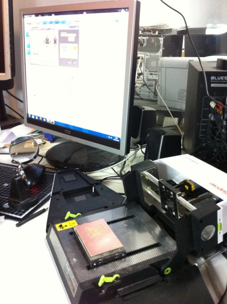
.ai and importing it in iModela Creator. 4/ Fixing the
FR1 board with
double tape to the iModela platform. 5/ Carefully
confirming planarity
of the FR1 PCB set in the iModela; 7/ Setting the
milling parameters as
described above; 8/ Milling; 7/ Watching the milling
process carefully
and stopping it after the 0.01 or 0.02 mm layer has been
milled. 9/
Washing the board and if necessary cleaning minor
details with a
precission knife; 10/ Cutting the board perimeter with a
precission
table-top saw. 11/ Applying lacquer to prevent
oxidation.
The second
and/or third board i wanted to make this week are the
hello.arduino.168
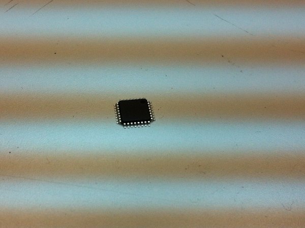
and the fabduino. For these two, again, i had to order
new components,
basically the ATmega168 smd microcontroller.
Some weeks
ago i had drawn in cad the ATmega168 and double checked
the geometry
just to see how tight it is and how much the milling
machine has to be
demanded. It
looks to me like the Fabduino is even tighter than the
hello.arduino,
so i decided again to start from the "beginning" and try
first the
former, which i milled and stuffed, leaving some
components waiting to
leave space to be able to solder de micro as comfortably
as possible.
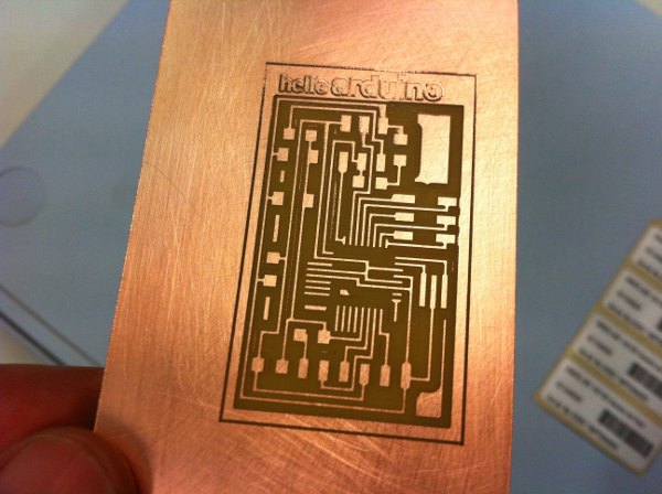
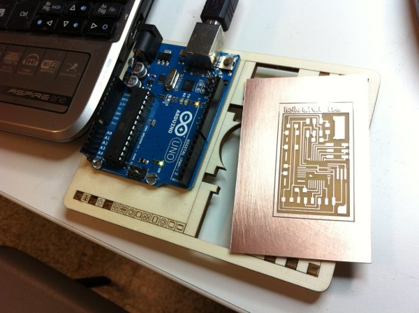
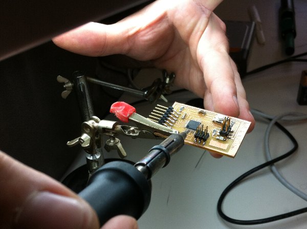
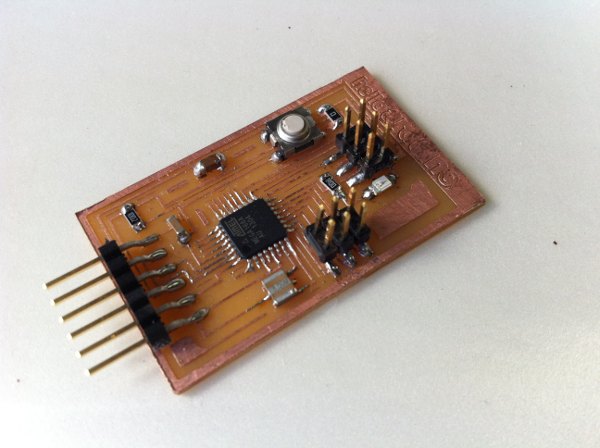
Milling the
hello.arduino.168 board; performing a little surgery to
it to get a
quite nice result; the hello.arduino.168 milled board
with an Arduino
Uno. Stuffing the board, which had to remain waiting for
some supplies.
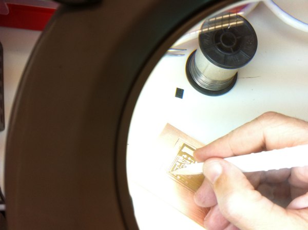
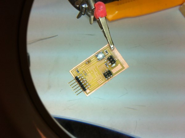
Monday
early
afternoon we got the supplies. Thursday to Monday by
digikey,
pretty excellent! And we went on with soldering. The
pins of the
Atmega168 are truly tiny... They make me almost
dizzy...
[practicing
with Arduino]
While
waiting
for the components i thought it a good idea to advance
some with a
regular Arduino board. I did find an example that
actually uses an
H-Bridge IC to control a DC - it is one of the projects
in the
excellent Arduino
Projects Book
edited among others by Massimo Banzi, Tom Igoe and David
Mellis, the
former very involved with the Fab Academy as we are
using an ISP design
by him.
To start with i
reinstalled the Arduino IDE without much trouble...
Ubuntu 10.04, still
has minor problems with it - managing the serial
connection... The error message is omething like
RXTX
Warning: Removing stale lock
file. /var/lock/LCK... which googling it, it
seems i am not the
only one with the same problem. It looks though that
using arduino as
root [sudo] lets me work ok; until now.
Of course
i have to update to 12.04, but i need some time to back
up
etc, that i cannot find... Hmmm.
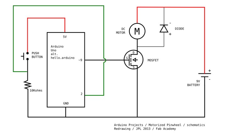
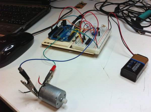
In order to
better understand the working so the devices first i
redrew the
schematics and made a diagram of my own, for a project
called
"Pinwheel" that uses a DC motor and a Mosfet to control
it. It was
helpful, i have to say. Then i rewrote the code and
compiled ok.

Below the
schematics - with some coloring - for and Arduino
controlling a DC
motor using a Mosfet [transistor], the above mentioned
"Pinwheel"
project. From the Arduino
Projecs
Book, p:95: "Transistors
are components that allow you to control high current
and high voltage
power sources from the low current output of the
Arduino. You can think
of transistors as digital switches. When you provide
voltage to one of
the transistor's pins, called the gate, it closes the
circuit between
the other two pins, called the source and the drain.
This way you can
turn a higher current/voltage on and off with your
Arduino." And this is the
Arduino sketch that can run this configuration [written
by to get some
practice me following the instructions]: arduino_projects_09_pinwheel.
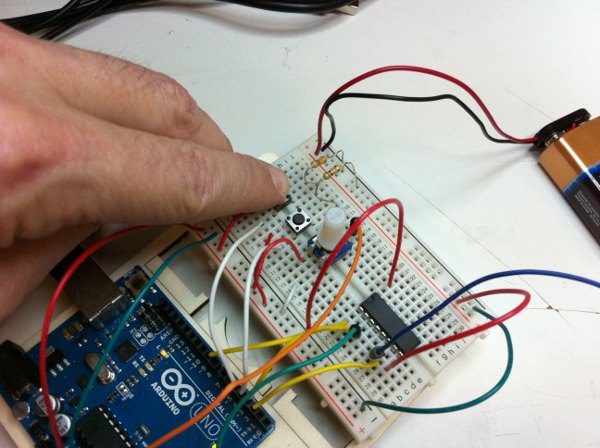
Now, the
commented
schematics of project 10 of the Arduino
Projects
Book, "Zoetrope", that uses an H-bridge chip,
with some
other elements, to run a motor back and forward, and
with different
speeds. This is the arduino IDE file, again written by
me to get some
practice: arduino_projects_10_zoetrope.
One
of
the
intersting
issues of this sketch is that the on/off and
direction of the motor are controled by two switches,
implementing
through code a comparison between actual and previous
states.
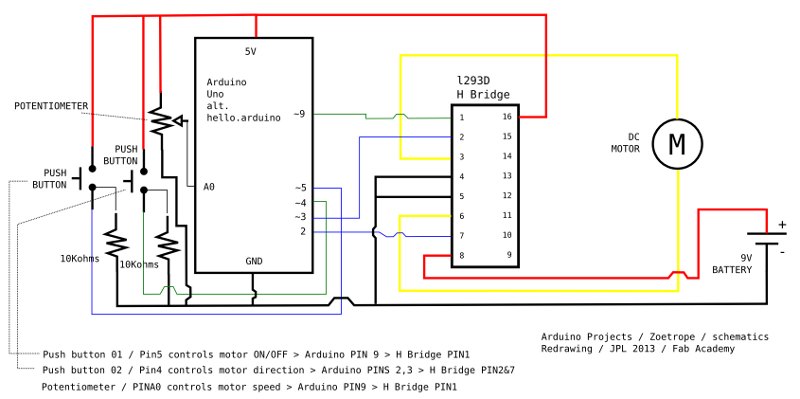
The other pins: The h-bridge gets its power through Pin16 [Arduino 5V]. Pins4 and 5 are both connectet to ground. Pin3 and Pin6 are connected to the motor leads. Pin8 is connected to the battery power [+].
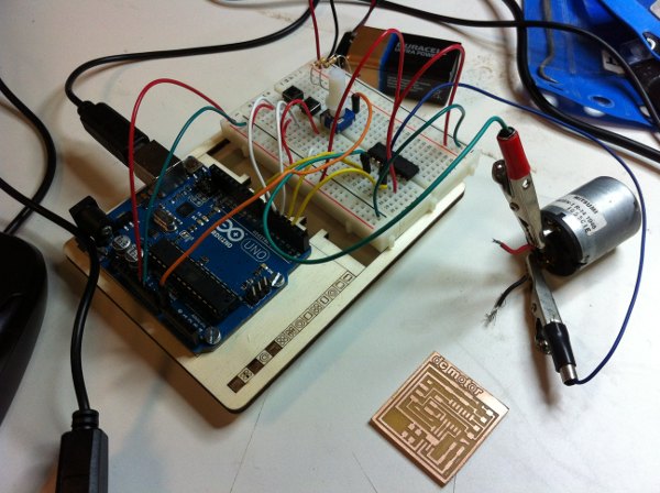
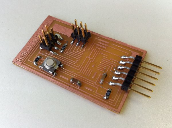
Final picture, to the right, with the dc motor hello.bridge.44 board waiting to be stuffed and loaded. Still monday night...
Video on vimeo: https://vimeo.com/64512118
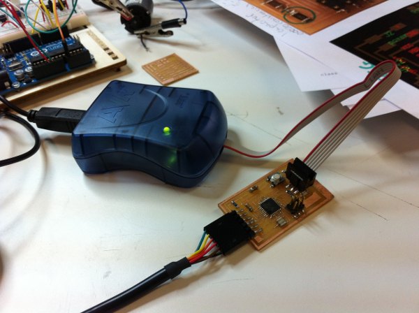
[bootloading the hello.arduino board]
Once stuffed, we were eager to see whether the bootloading would work. We went for AS220, Anna K's tutorial, and followed the steps, on my Ubuntu 10.04 machine. I had installed, as mentioned, Arduino 1.0.4. Connecting the FTDI cable, the AvrispII... First we got red. Then we changed the AvrispII connector, as can be seen in the picture and we got the green light! The board was receiving power! Almost too good to be true, - as Miss Lauryn Hill would say.
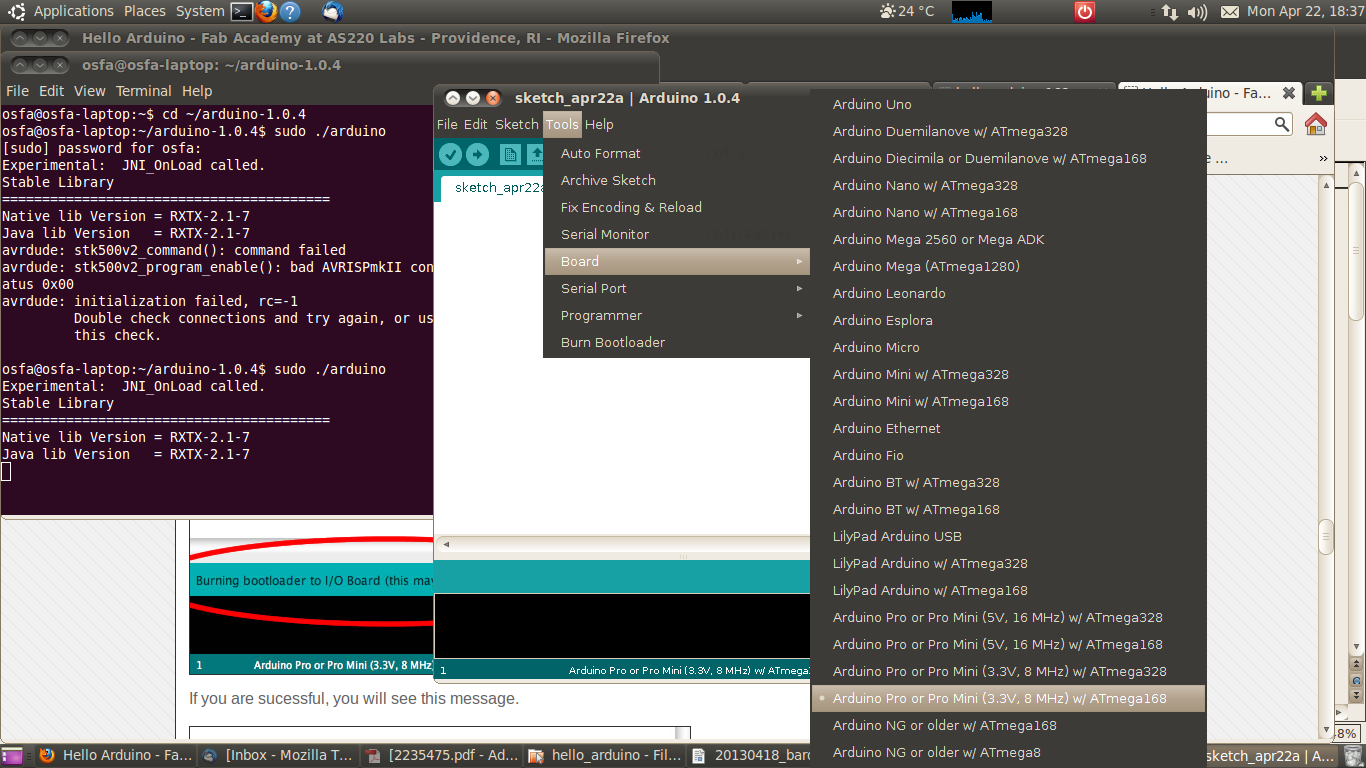
Then we went for the Arduino IDE. Following Anna's tutorial steps:
1/ Tools/Board > Arduino Pro or Pro Mini (3.3V, 8MHz) w/ Atmega168;
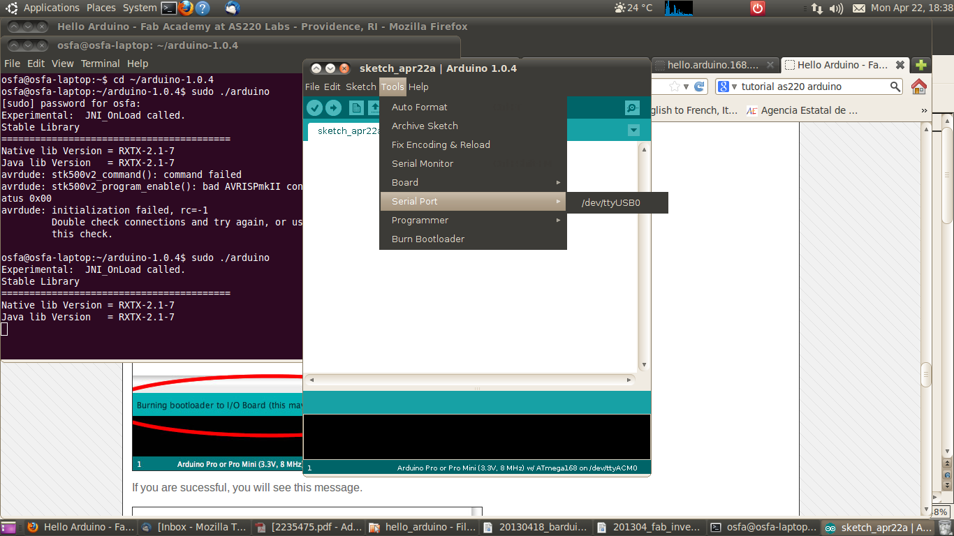
2/ Tools/Serial Port = dev/ttyUSB0 - which came out by itself;
3/ Tools/Programmer > AVRISP mkII,
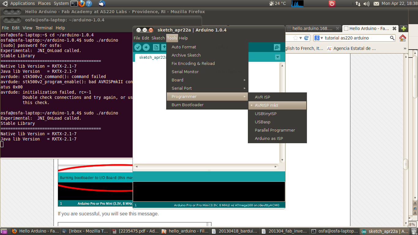
and next...
4/ Tools/Burn Bootloader... But here, dissapointment, it didn't work...
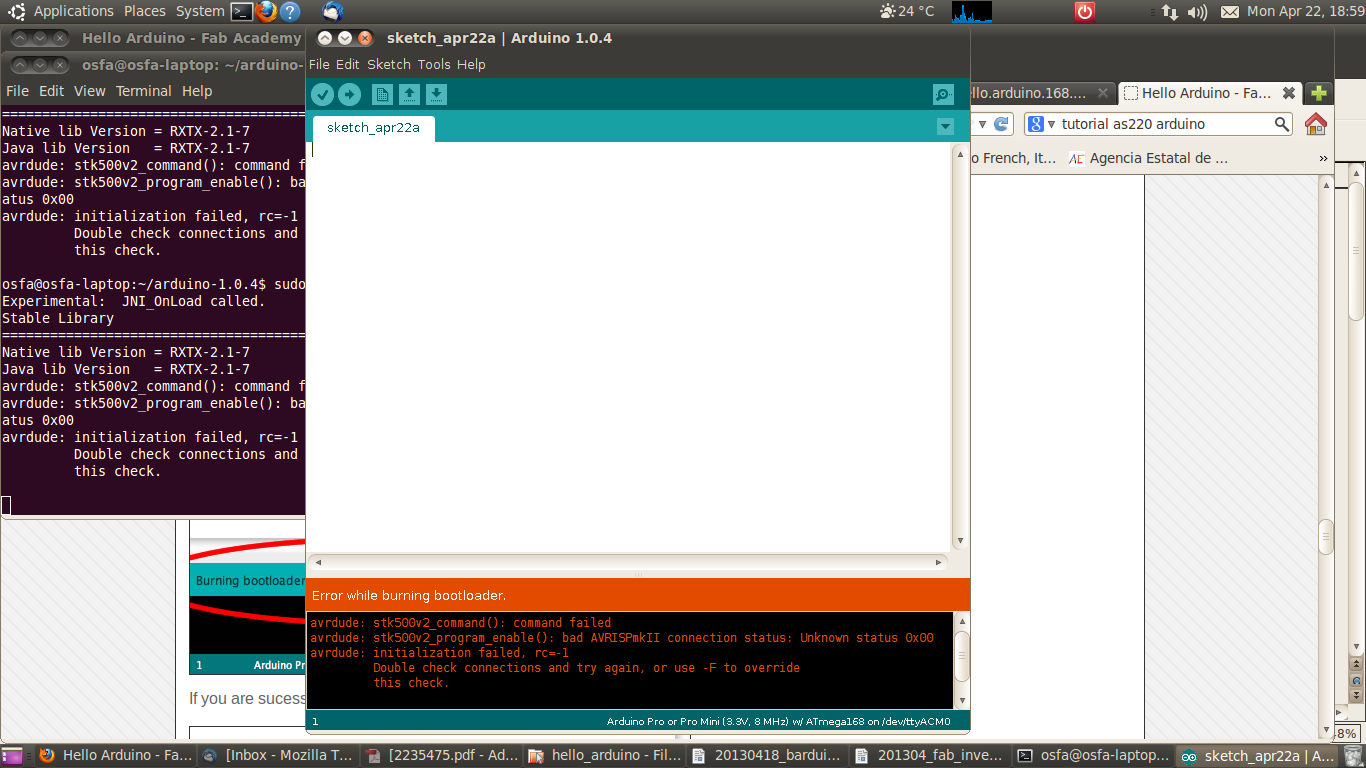
First error message:
Error while burning bootloader
avrdude stk500v2_command(): command failed
avrdude stk500v2_program_enable(): bad AVRISPmkII connection status: unknown
status 0X00
avrdude: initialization failed, rc-1
Double check connection and try again, or use -F to override this check
Debugging time!
First of all we moved to a Windows machine, that had worked better than my computer bootloading boards las time we tried. We had to find the right version of the Arduino IDE that includes the correct driver, and again it didn't work.
So we changed to checking the board. Jose Buzon had been helping me today. Indeed, stuffing it i had had a bit of a mess soldering the ISP connector... Jose who is much better than myself soldering went for it. We found out that i had soldered the LED with the wrong polarity as well. To make sure that i hadn't lost the Reset pin, which was the one i had had a mess with, we soldered an externel cable to the Jumper...
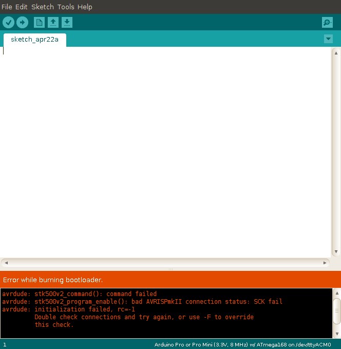
And back to trying the bootloading. It didn't work, but now the error was a little different pointing to SCK, maybe more trouble with the ISP connector? [...]
So a bit dissapointed after working quite a lot during this week, this is as far as i got Monday night this week. Tomorrow we will get some more components that we are still missing - we had the wrong H-bridges - and i will solder and try to bootload the hello.h.bridge.44 board... And continue debugging the hello.arduino board. I will probably mill and solder a new one two; even if i feel that the ATmega168 leads are a bit too much for me...
[additional work]
For the final project i include several output devices. On one hand i include a bipolar stepper motor; on the other i have several LEDs as ouput devices, that blink in different combinations according to the variation in the input devices included in the project, as well as a time condition. These I/O devices are designed as a combination of Arduino and an ad-hoc designed and fabricated "shield" boards. See link here: link >>
[files download]
Unless otherwise stated, information and files in this page are downloadable under a Creative Commons Attribution-Share A Like license; attribution: Jose Perez de Lama / Fab Lab Sevilla / Fab Academy 2013
[things used]
Software:: Fab Modules, Rhino, iModela Creator + Contoller, hello.H.bridge.44, avrdude, avrgcc, hello.arduino.168, Arduino IDE
Hardware:: iModela, hello.H.bridge board, hello.arduino.168 board, Arduino Uno, Avrisp II
Materials:: FR1 boards + components [see table]
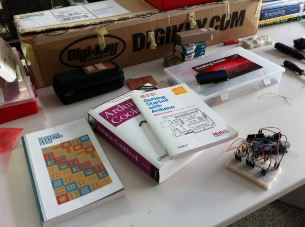
Bibliography:
Scott Fitzgerald, Michael Shiloh et ali., 2012, Arduino Projects Book [book distributed together with the Arduino Starter Kit], Arduino.cc
Michael Margolis, 2011, Arduino Cookbook. 2nd Edition, O'Reilly Media, Sebastopol
Massimo Banzi, 2009, Getting Started with Arduino, O'Reilly Media, Sebastopol
previous class:: 12 interface & applications / next class:: 14 networking & com
return home /perezdelama.jose