Final project
Final project
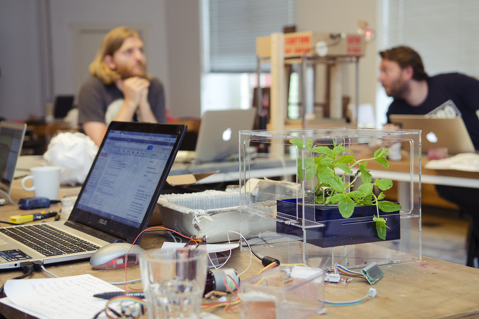
 For my project, i am making an hydroponics module, which can operate fully autonomously and communicate with other modules to ask for water or nutrients. During the plant’s growth process, the system will record temperature, light and water level. This data can be recorded on a computer and/or will be displayed on a lcd screen. In the next version, i am planning to add led lighting, humidity and acidity measurement. There are five main parts to this project:
- to make an encasing to keep everything together.
- to make a watertight container to store the water with a connection to the valve.
- gearbox to give extra power to the motor open the valve.
- pcb input and and output boards
- communication over the bus within the module and with the other modules.
1. encasing (skills: 2d-design,3d-design, laser cutter)
programs used: openscad, inkscape, illustrator
materials used: 3mm MDF, 3mm transparent acrylic
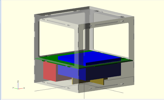
To have a impression, of how big the encasing would be and how everything would fit together, i made a MDF encasing with the shopbot. There were several issues with this MDF model, which i did not take into account when i started this project. First, the MDF model 30 cm cubed was too big and too chunky. Second, when MDF gets wet, it will quickly fall apart. Third, the material blocks the sun for the plant, which it need to grow. Fourth, the model at that moment, located the water container in the middle of the encasing, which was also not a good position for the plant to be. Fifth, i forgot that when you want to connect the 4 different vertical sides, you have to take into account that you need tabs.
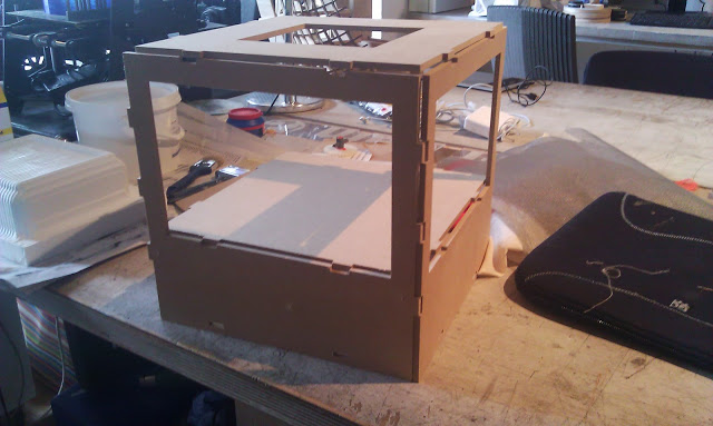
I decided that i needed another material. I choose transparent acryl. This would eliminate most of the problems mentioned above. I reduced the size of the model to 25 cm, which would be a more manageable size. I spoke with my fellow fablabbers and they recommend to use 3mm transparent acryl. I bought the acryl as soon as i could and continued designing the model.
The encasing model is 2d design, but i used 3d design in openscad to see if all the components would exactly fit into the encasing.

The 2d design of the encasing falls apart into three parts:
- press-fit connection (male and female around the flats and sides)
- flats (3 horizontal)
- sides (4 vertical)
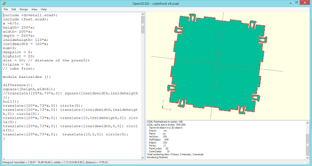
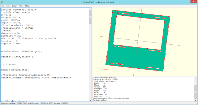
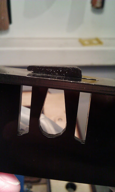
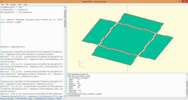
The hardest part was the press-fit connection. I knew that i would never be able to make it in one go, so i tried to make a parametric model. which i could easily adapt on the fly. I have tried several versions to get it to fit perfectly. I did not realise however that 3 mm is not always 3mm for every acrylic plate. I learned that the hard way. I am not familiar with acryl and i did not realise that you should not make connection too thin. Acryl is not very strong when it’s too thin and stiff when it’s too thick. It was very difficult to find the optimal point, where i could easily bent the press-fit and where it would not break. I think it found it, but i am still not 100% happy with it. Maybe i should consider another press-fit design, but as i was pressed for time i had to accept that i would be able to find the optimal one.
The flats are 2d designed and are merged with the press-fit connection to make the male part of the press-fit connection. These are also parametric. So when the dimensions of the encasing are changed then the press-fits are automatically rearranged and when i change the press-fits these are changed on the flats.
The third step was to design the vertical sides and orientate the female part of the press-fit connection at right height and correct size. This depended on the thickness of the material, which posed some serious problems to get it to fit.
When i designed all the 2d components, i decide to extrude all the parts with the thickness of the material and then actually 3d design the model and this really helped me to get the material to fit exactly
design files:
2. water container (skills: 3d design, shopbot, composite)
programs used: openscad, inkscape, illustrator
materials used: smooth-cast 310, different layers of garment, vaseline, gesso, glue(gun)
3d-design
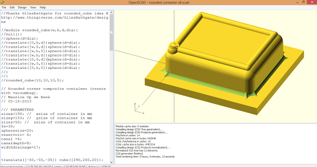
I had not made a composite as we had some serious problems making a vacuum bag from scratch, but i decided i would make one for my hydroponics system. I was assuming that a composite would be watertight, but that proved not to be the case. I had never made a composite before and at fablab amsterdam there was little prior experience with this methods, so i experimented with a vacuum bag, which rick had bought a few weeks earlier. I 3d-designed a container in openscad with rounded curves and a reservoir for the water, which would lead to the drainage and the geared valve.
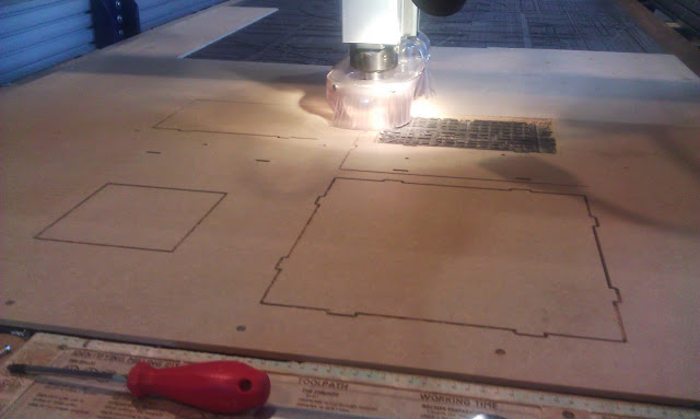
The container needed to be relatively deep, so i was limited to the drills i could use and the material. I used a ˝ inch drill and foam to cut out the 3d designed container. The height of the foam was higher than the material could handle, so together with takoma, we changed the g-code, so i would go exactly to the limit of what it could handle. The shopbot milled out a rough and fine trace of the model. I was assuming that i would not be able to get a very fine finish as i was using a ˝ inch drill, but i realised later that i could have decreased the stepover for finer finish. The model is relatively rough, but i decided that i actually looks pretty cool. I painted the foam model with gesso and let it dry for 3 hours and then i would paint it again the next day.
making the composite
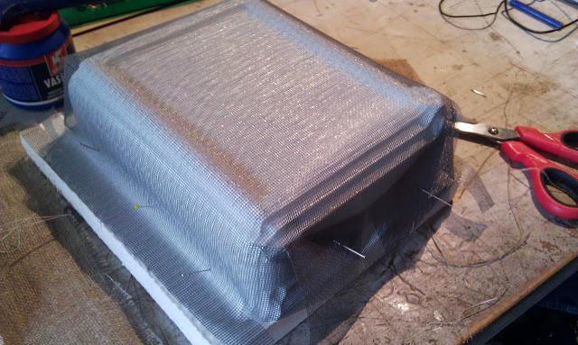
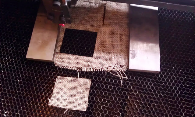
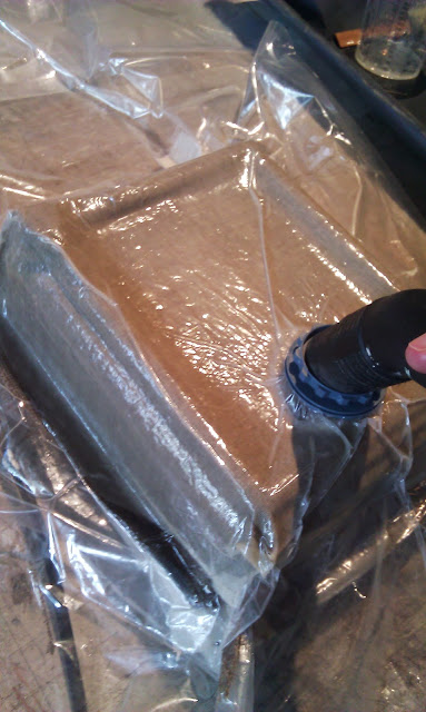
I used 4 layers of garment and smooth-cast 310 for my composite. I cut the pieces of garments as i realised that uncut garments would bulge around the corners, which would not make a nice composite. I tried if i could cut a piece of burlap in the laser cutter as it’s very hard to cut with a scissor. It worked actually very well, but i realised that i would lose precious time designing the cut pattern and i decided to cut it by hand anyway. I covered the model and the vacuum bag in vaseline, prepared the smooth-cast 310 by mixing part A and B in equal quantities and i started to put the different layers onto the foam model. I used nails to keep the garment in place. I put four layers of fabric on the model and i used a brush to paint the smooth-cast onto every layer of fabric. The smooth cast was going to harden in 20 minutes, so i had enough time to get it prepared before i put it in the vaseline covered vacuum bag. I connected the vacuum cleaner to the vacuum bag and i realised that i had made a mistake. I should not have put the opening of the vacuum bag on top of the model. The suction of the vacuum cleaner pulls the smooth-cast up and around the opening of the vacuum bag. This created an ugly part on my composite as you can see on the picture. I left the vacuum cleaner suck for around 15 minutes and i noticed that the smooth cast started to harden in the cup of leftover smooth cast and turned of the vacuum cleaner. I left the model to rest for a couple of hours, before i took it out of the vacuum bag. The composite was strong and lightweight, but it proved to be not watertight. I could have solved this problem by adding more smooth-cast and moving it around the bottom, but i realised that the composite had turned out to be much larger than i had expected, due to the extra layers of garment. I soon realised that it would not fit into the encasing i had designed.
acrylic container
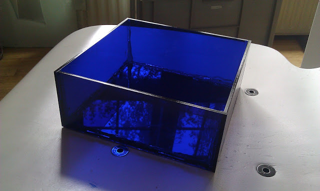
I needed an alternative and it dawned on me after playing with acryl for a while that i could make a perfectly fitting, watertight container with acryl and glue (or silicone gel). I used glue, but in hindsight, i think silicone gel would have been a better solution. I started designing the box in openscad and cut out the parts the parts on the laser cutter. I did have some practise with the encasing, so i had done this relatively quickly. I used the glue gun to stick the 4 side panels and the bottom together. The acrylic container was not watertight in the first try, so it took me several tries to close all the holes in the bottom. In the end i managed to make a watertight container, which would fit my encasing.
design files:
3. gearbox (skills: 2d and 3d design, 3d printing, laser cutting, mechanics)
programs used: openscad, inkscape, illustrator, cura
materials used: PLA
gears
I bought a water valve in a shop and at the time, i did not realise that for opening and closing the valve, i needed a relatively strong force. When we worked on the machine mechanics project, we noticed that the stepper motor we used was relatively weak. I asked Bas, what i could do and he proposed that i added gears to increase the power of the motor. The laser cutter was down for a couple of days and at the time, we did not know if it would be up and running on time, so i decided to 3d print my gears.
3-d printed
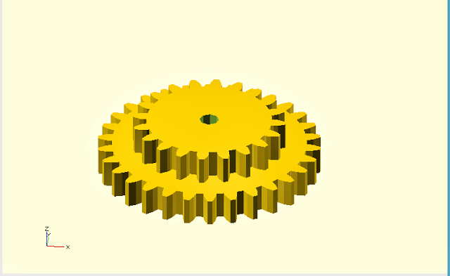
I designed the gears with inkscape and openscad. This Inkscape has a very handy feature to make gears under the extensions/render/gear tab.
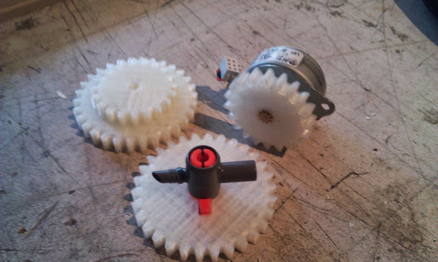
I decided not change the circular pitch and pressure angle and make three different different gears (10, 20 and 30 teeth). The 10 teeth proved to be too small, so i only used the 20 and 30 teeth gears. In total, i printed 3 different gears :
- gear to connect with valve
- gear to connect with motor
- stacked gear that would connect the force from the motor to the valve
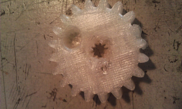
I used openscad to linear_extrude the dxf exported gears and then printed the models with cura on the ultimaker. This was a relatively straightforward process and i did not encounter any problems with the 3 printing. To print, I used michaels settings in cura and set the material to PLA.
I did encounter a problem with getting the 3d printed gear connected with the motor. On the motor there is a 10 star brass connection and i designed it in inkscape to fit exactly. It did fit, but i was still too loose and it over time this connection would loosen too much, so i printed the gear again but this time with a tighter hole. I tried to press it in, but it did not fit anymore. Takoma suggested that i heat the brass connection with the heat gun and then melt the 3d printed gear over it. I held the heat gun too close to the plastic and this melted. I printed the gear one more time and this time, i only heated the brass connection and i pressed it through the plastic. It worked, but still gear ended up a little deformed. I decided that i was better off with an acrylic gear. The laser cutter had been repaired and i started designing the gear for the laser cutter.
lasercut gear
Working with the laser cutter is much faster than with the 3d printer and i had relatively quickly made a gear that would fit onto the motor and would latch onto the 3d printed gears. As i mentioned before, i needed to use a different motors, which meant that i had to make a new gear. The geared dc motor did not have a brass 10 spoke connection, but a hole in the shaft. Bas advised to make a small stick that would fit into the hole in the shaft and then would press fit in the inside of the gear. The gear would still move freely over the shaft, so i made 2 other similar gears which i glued together on both sides the original gear with the stick.
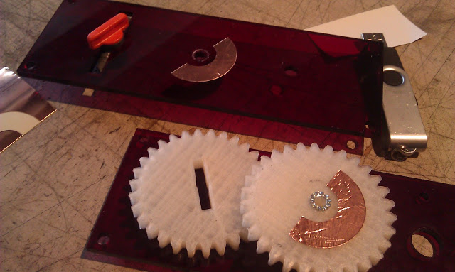
gearbox
Next stop was to make an gearbox that would house all the gears and would allow for a connection with the motor and the valve. I aligned the gears and put a piece of paper under it and with a pen, i marked where the centers of all three gears were. Then i started designing the gearbox in openscad with this data.
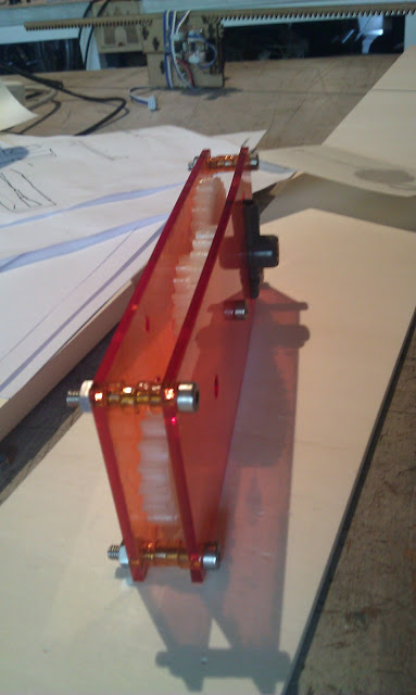
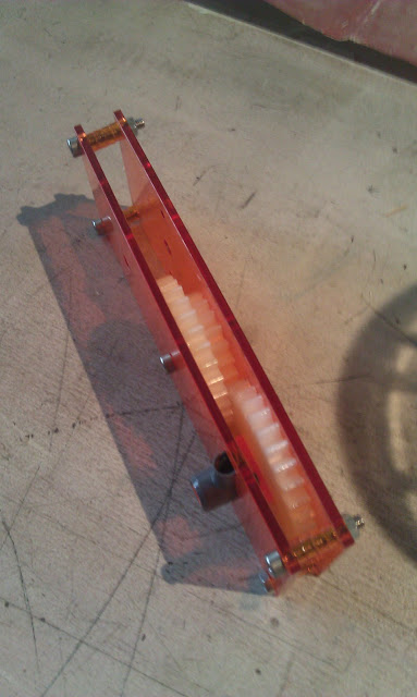
I cut the gearbox and put all the parts together. Here i found out that acrylic can break easily if you make the connections to small. I used screws and bolts to put the gearbox together and washers to reduce the friction between the walls of the gearbox and the gears itself.
Although the gears reduced the force needed to open and close the valve, it still was not enough. I consulted with bas and he recommend that i use a geared dc motor. This changed my design for the gearbox and affected my encasing design.
design files:
- gear to connect to motor, (gearsv6small.dxf)
- gear to connect to valve
- stacked gear, (gearsv6big.dxf, gearsv6small.dxf)
- gear box encasing
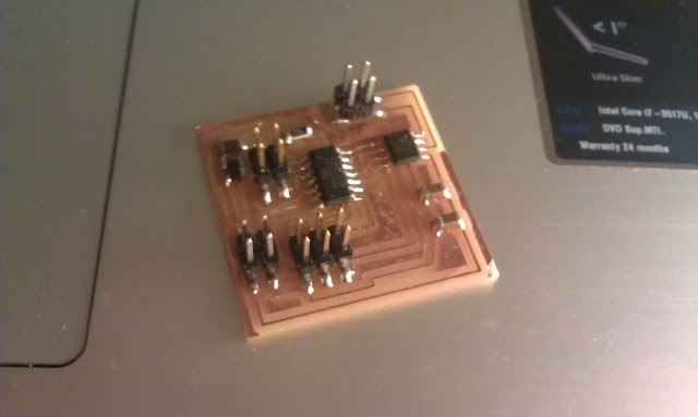
4. pcb boards (skills: pcb design, pcb fabrication, modela, programming)
programs used: eagle, fab modules
Materials used: pcb board, various components
short introduction
I wanted to add as many boards to the hydroponics cube as i could and time would allow, but i quickly found out that i had to choose as time was ticking very fast and i thought it was better to have a least the essentials and i would add more later. At the very least, i wanted to have a water measuring board, motor pcb board (to open valve), a LCD and a bus network communication system.
initial testing of bus communication
I started off using the bus bridge communication board to see if i could communicate with all the input and output boards. I changed the code of hello.light, hello.temp, hello.txrx to include the bus communication and assigned them an unique node number. When connected to the bus network, I managed to ask information for each of the board. I had some issues with the LCD and motor board with regard as i would supply the board with two power supply sources. I realised later that i could have rerouted the vcc cable for the LCD and motor board, but i decided to make a new motor board with a separate communication channel and energy supply.
barduino
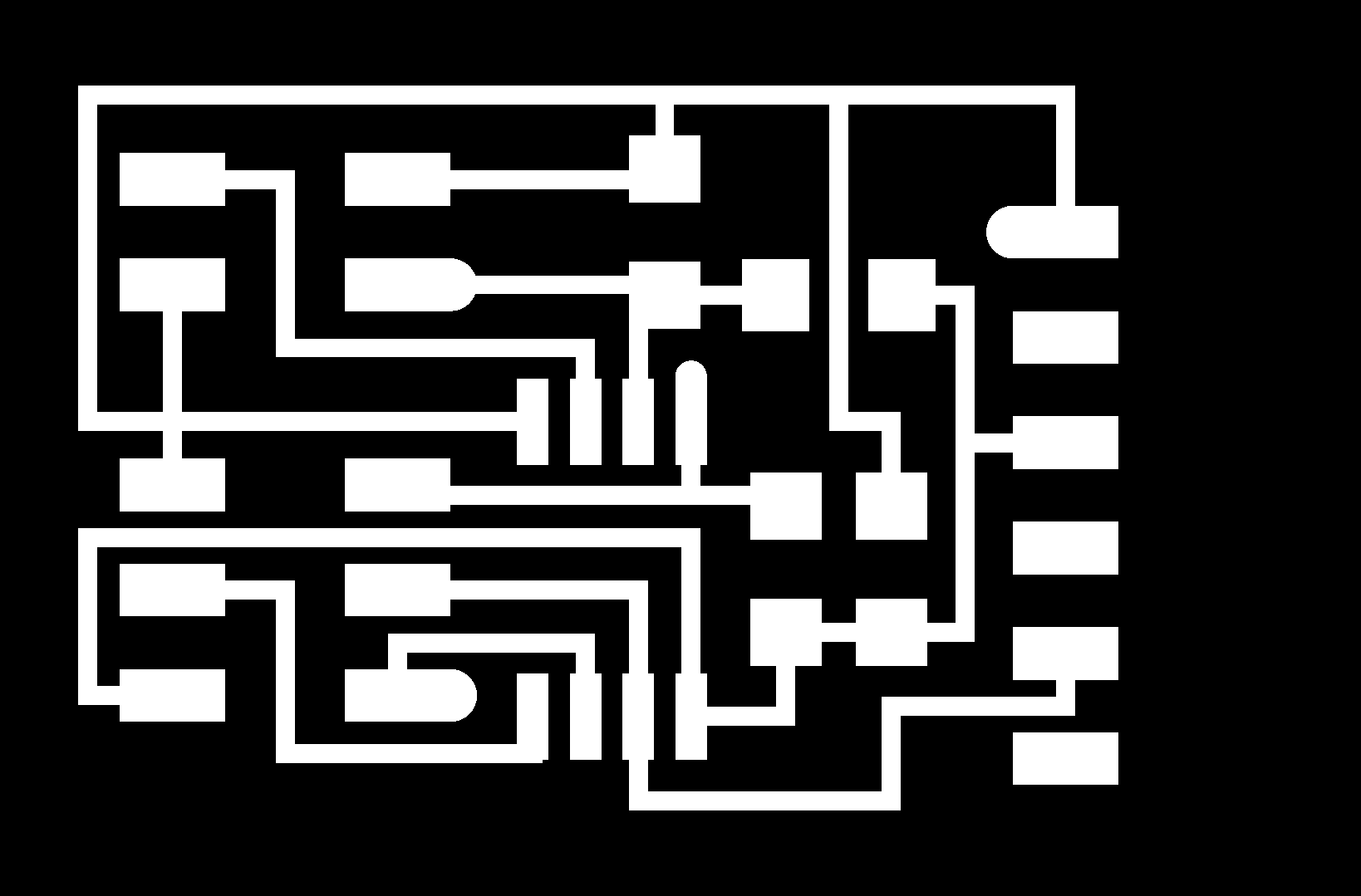
I needed a versatile board, so i looked at barduino as my master board. It has a atmega328 processor and it has many pins, where i can connect my boards to. I made it, but i could not get it to work. I realised that when i use a board someone else makes, i do not know exactly how everything works. Bas proposed that i make my own board with a communication, power and FTDI connection. I decided that i wanted the LCD also to be directed connected to this board. I used eagle to design the board. I learned the hard way, that it is not a good idea to design your pcb board in the middle of the night. In the end, i made this board again as i had forgotten some vital connection.
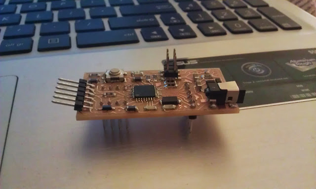
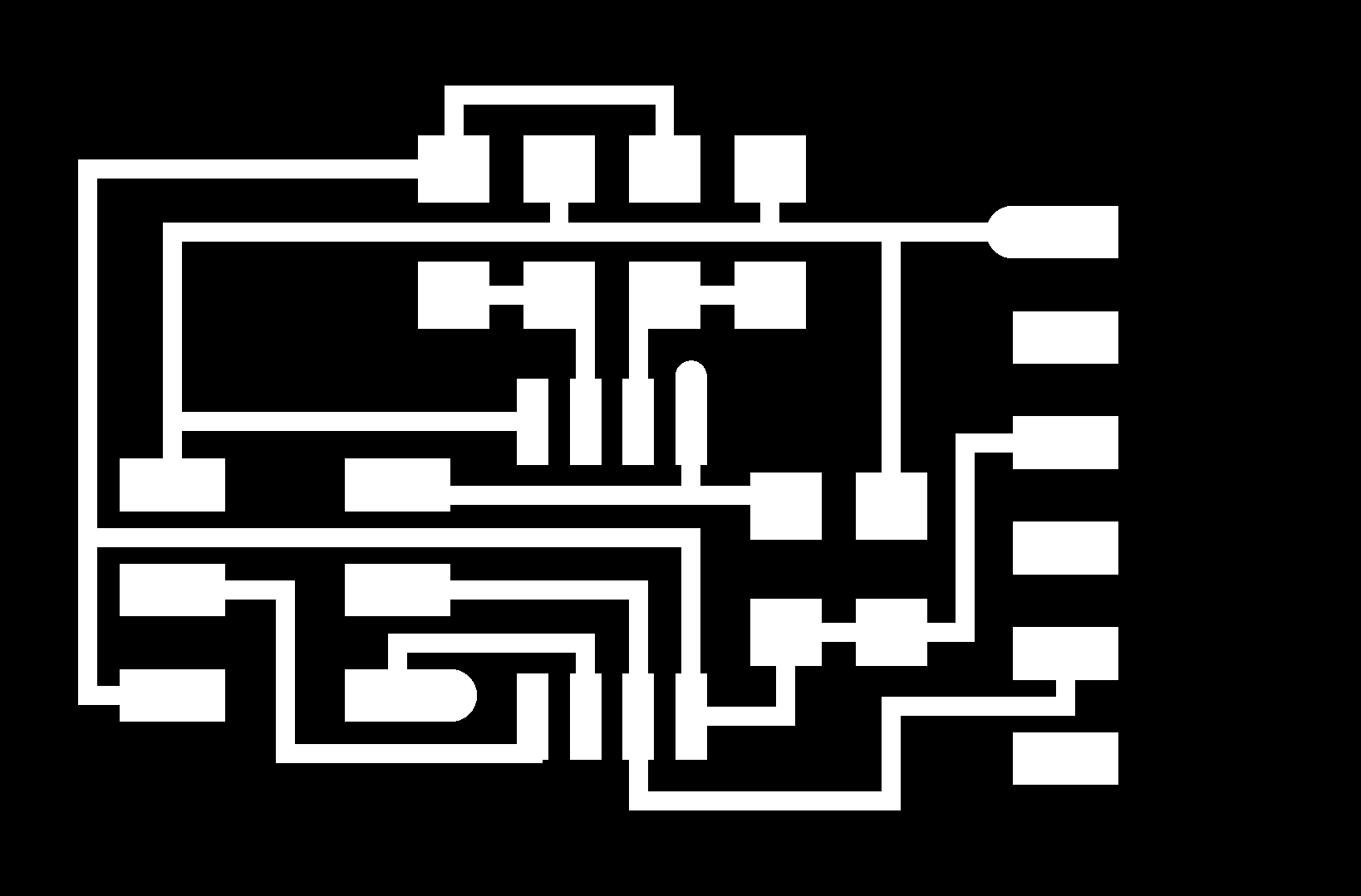
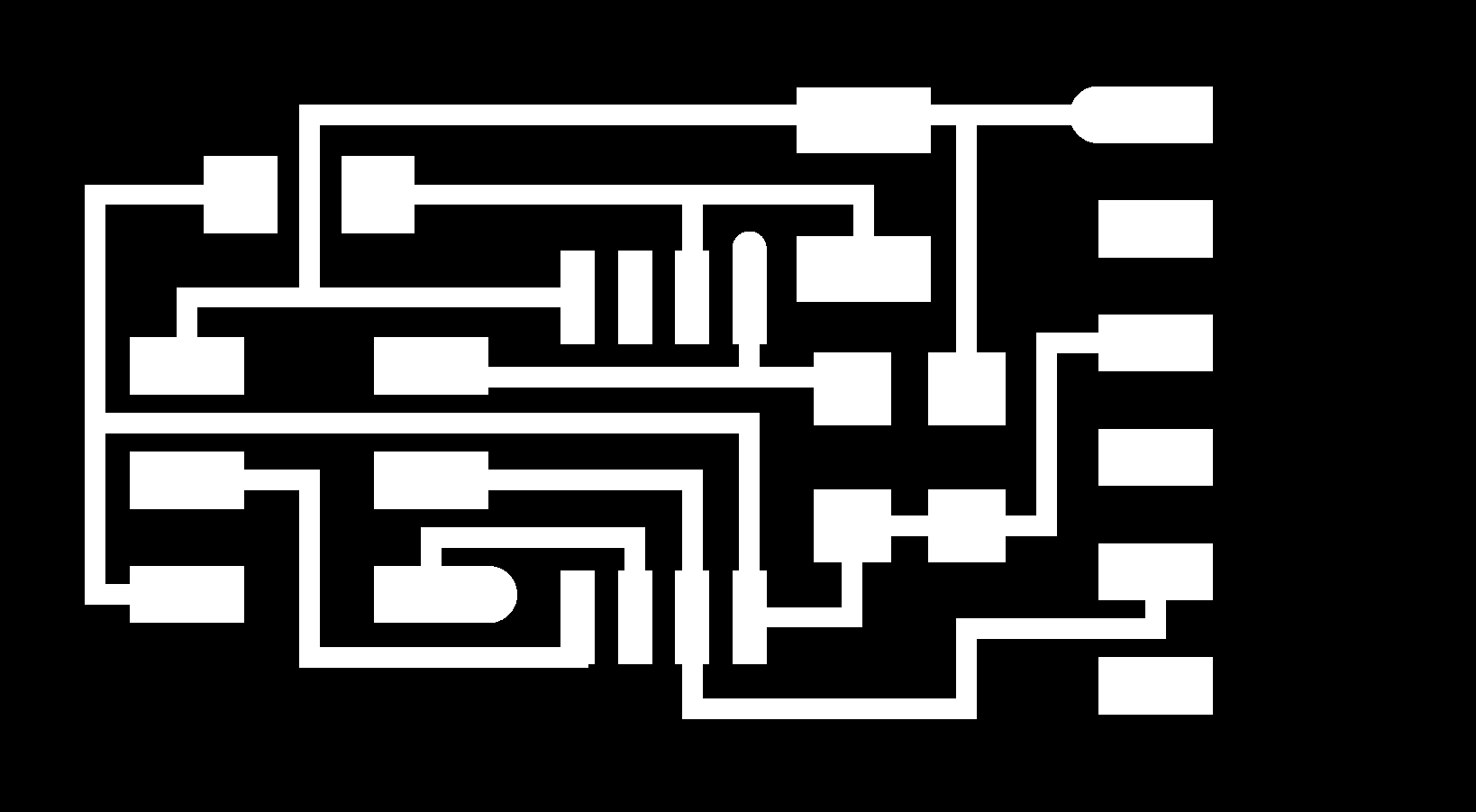
hydro main board
Bas recommended that i add the LCD directly to the mainboard. The board i used to test the bus connection used an attiny45, which did not have enough memory to store all the c code to handle all the tasks, so i needed a main board with a bigger processor. I chose to use the atmega328 as this chip has enough ports and memory to deal with all the requirements of my project.
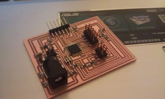
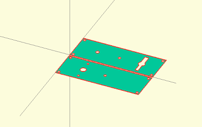
I needed a steady power supply and bas recommended i use a 5.5mm jack. Unfortunately, this component was not available in the eagle library, so i had to make it myself. I used windows snipping tool to get the layout of the part from the datasheet and stored that picture into a bitmap format. Eagle can import and scale the component to the right dimensions. I needed to connect this to a schematic (i used a schematic from another jack) and then with device connect the package with the schematic.
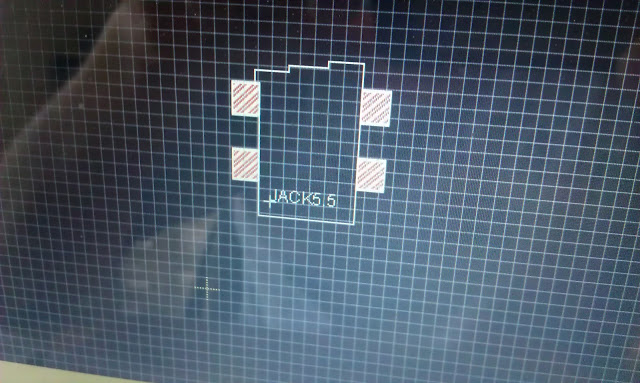
I did have a problem with this package when i started the board design. As you can see on the picture, the package is a away from the zero point. When i used this package in the actual board design, the footprint of the jack included the zero point, so when i rotated the image, it would rotate around the zero point. I solved the problem by moving the jack to the zero point in the library.
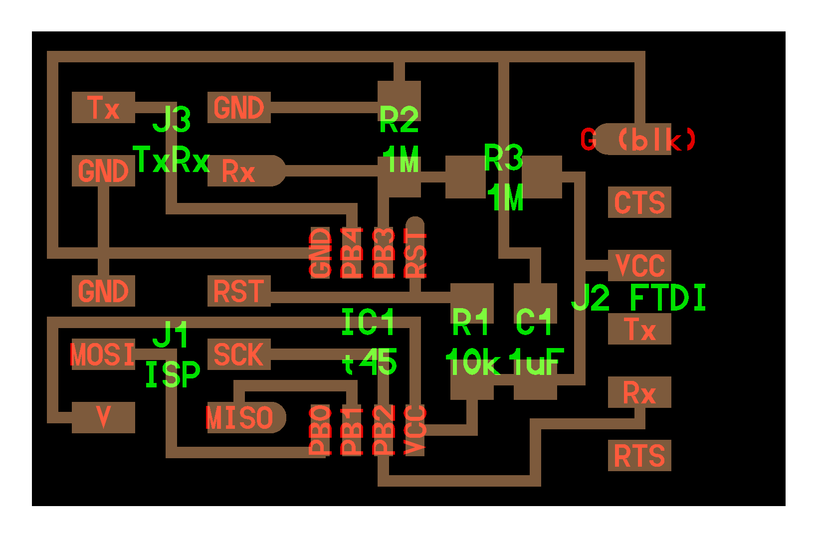
hydro input (temperature, light, water level and valve feedback for motor)
I changed the hello.temp, light and txrx program to include neil’s hello.bus program, so the master can ask for the temperature, light or water level. The response of these boards can be the actual or average reading.
- temperature board,traces,outline , temperature C program, temperature make file
- light board,traces,outline, light C program, light make file
- water level board,traces,outline, water level program, water level make file
hydro output (motor and lcd)
I have two output devices connected to my main board. The LCD is connected directly to the main board and the dc motor can be controlled via the bus communication. I started off using a hello.stepper board, but the board was getting very hot. I realised that the battery power and the power via the bus communication cable was too much power for the board. I redesigned the board, but realised later that it would have been easier to reroute the power cable for the motor. The stepper was not strong enough, so i needed design another board for a geared dc motor.
I have not been able to completely finish my assignment. I have not been able to control the motor and put everything together, but i can measure the water level and display it on the lcd panel.
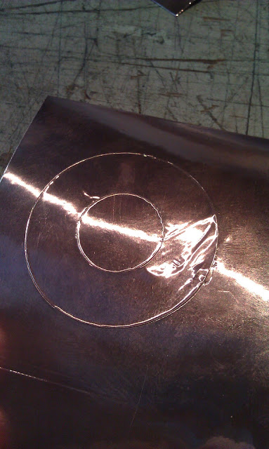
5. feedback connection (vinyl cutter)
The motor needed a feedback system, so it can tell how far it has opened the valve. I cut a circle in the copper sheet on the vinyl cutter, which would serve as sensors for how far the valve had been opened. These sensors would be placed onto on of the gears and on the gearbox. The amount of overlap of these sensors determines how far the valve has been opened or closed. The hello.txrx board will interpret this information and send it to the master board.
I have had some problems connecting to my motor board with my masterboard and after several days of looking for the fault, I realised that the txrx part of my pcb board was listening to the tx side instead of the rx side, which explains why i was getting a constant 1023 reading. After i had solved this problem, it was not very difficult to get the motor to listen to my feedback mechanism. In the video below, you can see that the motor start running after been given a command to turn left or right. I move the gearbox by hand in the video, but eventually the motor will turn this gearbox. The motor turns off right at the moment the two copper plates completely overlap eachother. This is exactly the point where the motor should stop. I did not put the motor into the gearbox, as i cannot control the speed of the motor. The motor turns to quickly and would destroy my gearbox. I will need to slow down the motor with PWM, but i did not have enough time to get it ready on time. When i have the speed of the motor under control, i can safely connect the motor to the gearbox and that would complete my project. To complete the hydroponics system, i do need to
6. What worked and what did not?
Encasing:
I made several cases and found out that an mdf encasing does not work well for this system as it does not let light through and it gets structurally weak when it gets wet. The transparant acrylic is better suited, but i found out that it is very brittle and can easily break. I was hard to find the optimal point where the connections would be strong enough, but would not consume to much space. If i would do this project again, i would use a ticker acrylic.
Water container:
I originally wanted to make my water container from a composite, but i could not get it water tight. I must admit that i would have been able to get it water tight, but i was pressed for time and i realised that due to multiple layers of garment the container turned out a little bigger than i expected. I quickly designed a acrylic water container, which made was a better choice in the end.
Gear Box:
I had problems connecting the gear to the DC motor shaft. The gears is held together with nuts and bolts. In a next version, i would change this also with a click system to reduce costs, but also to increase strength. The gears works perfectly within the gearbox, so i did not encounter any problems here.
Electronics:
I had some problems with electronics. I had to redesign several boards in order to let them communicate with the main board. I realised late in the project that i needed to merge the feedback motor system with the motor board as the chatter from the feedback would become to difficult to manage. I initially made a remade the fabduino board, but not having designed the board myself, i could not easily communicate with this board. I decided to make my own and added a connection for a LCD board. I made some errors while designing this board, so i ended up remaking this board several times. In the end, i managed to let the main board query all the input boards, display this information on the LCD and control the motor.
Putting it all together
I managed to get the encasing, gearbox and electronics working, but i did not yet managed to put it all together. I do not have full control over the motor, which does not allow me to open and close the valve in a controlled fashion. If can control this motor and add the tubing, this project should work the way i intended.
7. Bill of materials
Programs used:
- openscad
- inkscape
- illustrator
- cure
- eagle
- fab modules
Materials used:
- 3mm MDF (for trial encasing)
- 4x 0.50m2 3mm transparent acrylic (encasing)
- 1x 0.50m2 3mm blue transparant acrylic (water container)
- 1x 0.25m2 3mm red transparant acrylic (gear box)
- 1x geared dc motor (jameco reliapro p/n 253471)
- 1x valve (gardena)
- 3x attiny45 AVR micro controller (temperature, light, waterlevel)
- 1x atmega328 AVR micro controller (main board, LCD)
- 1x attiny44 AVR micro controller (motor board, feedback)
- 8x 10k resistors
- 1x 100k resistor
- 1x NTC thermistor
- 5x 6 pin connector
- 5x 4 pin connector
- 1x 10 pin connector
- 7x 1uF capacitor
- 2x 10uF capacitor
- 4x FTDI connector
- 1x 49.9k resistor
- 1x phototransistor
- 1x 100nF resistor
- 6x 0k resistors
- 4x 1M resistors
- 2x 5V regulators
- 1x JACK 5.5v
- 1x Cristal
- H-Bridge A4953
- copper pcb boards
- 200 ml smooth-cast 310 (
- different layers of garment
- vaseline
- gesso
- glue(gun)
- PLA for gears (3d printer)