week 14, apr 24
weekly assignment: build a wired &/or wireless network with at least two nodes
tutorial used
i used this excellent tutorial by the providence fablab:Networking - Hello Serial Bus
the electronics
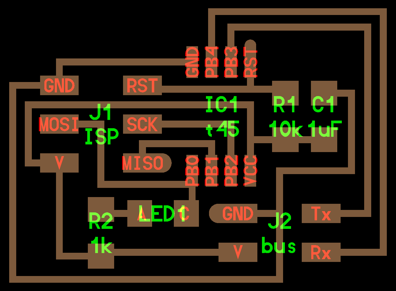
for this assignment 3 PCB's were milled and stuffed, 1 node with a bridge to connect to the FTDI cable, and 2 more nodes.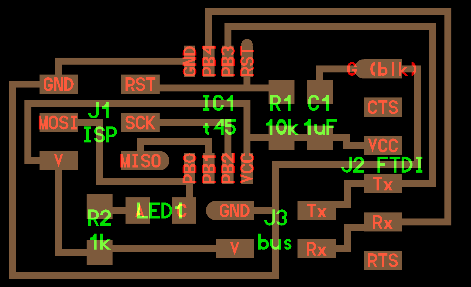
software enviroment: LINUX under windows
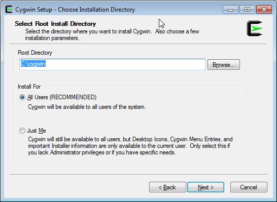
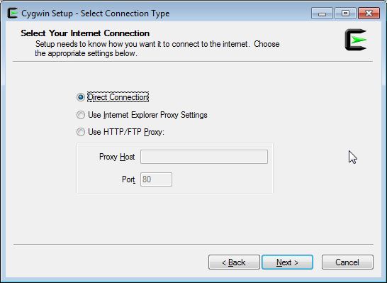
the programming of the boards is done in C, so i decided to install a LINUX enviroment under my windows 7 laptop.the chosen one was CYGWIN
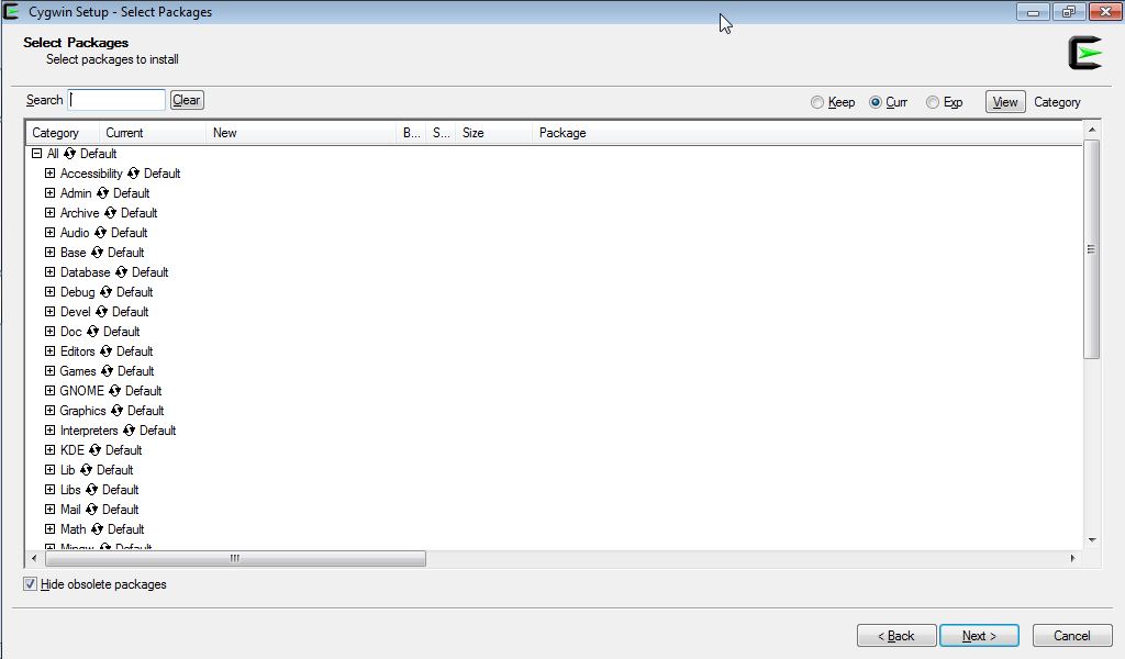
the installation was pretty straitghforward, when it asks what packages to install i chose all, just in case.
now i can open a linux terminal under windows!

programming
the programming of the nodes was done with an AVRISP programmer, since my fabisp board doesn't work anymore.i used the files from the providence tutorial to program my boards, since they supposedly fix some compilation program in neil's files, the fixed files can be found HERE
at first i set to program node #0 which is also the bridge. i typed the line suggested by the tutorial,
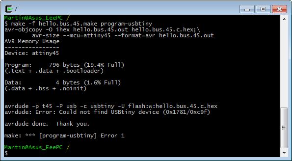
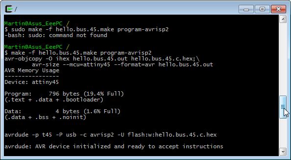
well first of all, and i don't know why yet, this terminal didn't like the sudo prefix, and second i didn't use the usbtiny! so i changed the line to:
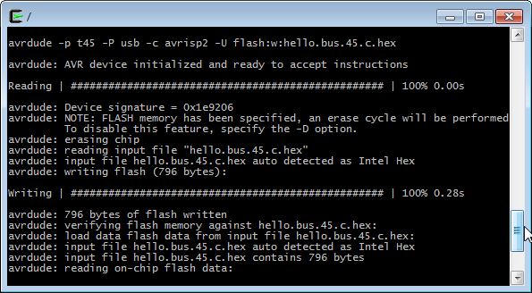
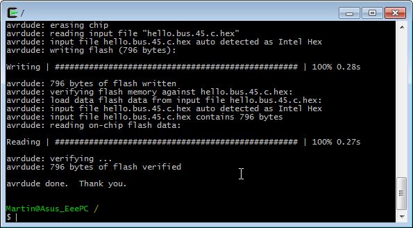
now it works!
so, take that into account if you use the AVRISP2 instead of the FABISP
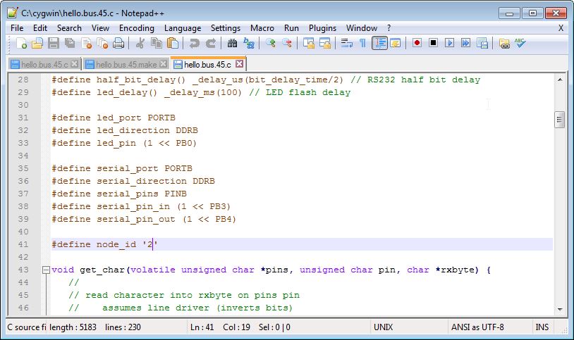
for each node that you program, you need to change the c-code with a unique ID so that they can be identified in the network.
i named the nodes "0", "1" and "2".
that is done in the define node_id line (see line 41 below).
cables and connections
before programming anything, you first need to connect the node boards.it goes like that:
double check: BLACK=GROUND
double check here too for correct polarity!
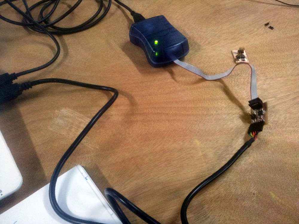
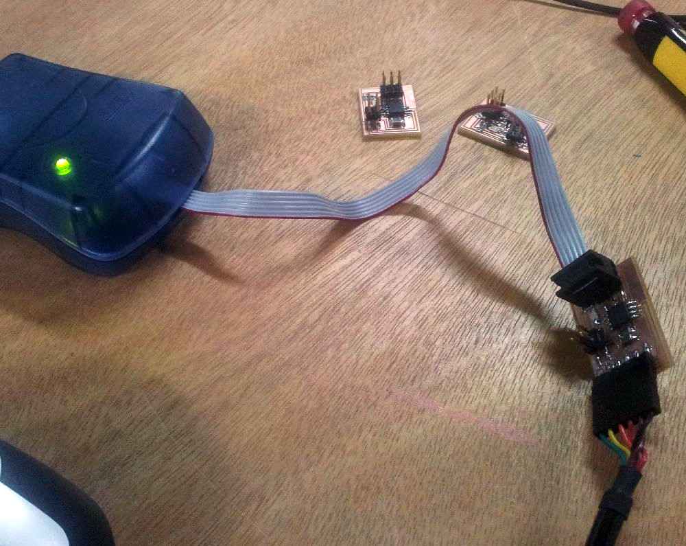
at this point you should see a green licght in the avrisp programmer.
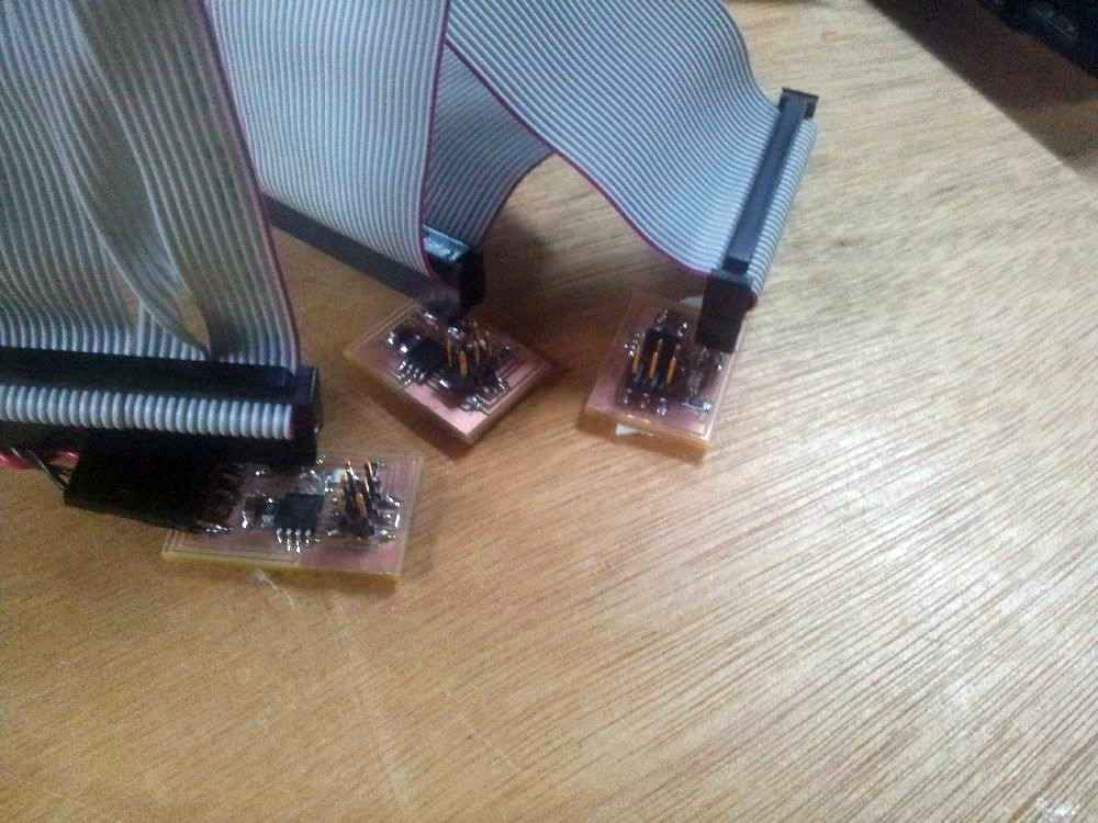
the next two pictures show see how i connected the system to program the bridge node, node #0:
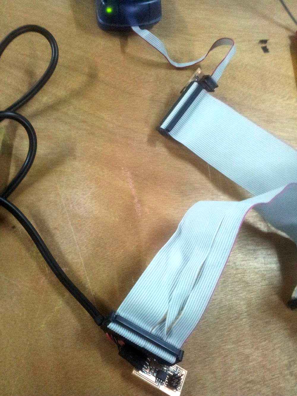
to program nodes #1 and #2 the bus flat cable was connected too. as can be seen we didn't have a 4 wire flat cable, so i used a wider cable scavenged from an old PC.
so, for each NODE you want to program you do as follows:
testing the network
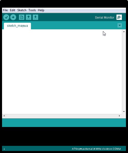
at this stage, the avrisp can be disconnected, we are done programming.to test the network, open the arduino IDE:
on the window that opens, you have a node text field, write the id number of one of the nodes (0, 1 or 2) and see what happens.
if everything is good, the window will echo the name of the node (e.g. "node 0") and the nodes LEDs will light:
first all three leds blink together, and then the "0" node blinks once again.