 2013
2013 2013
2013make something BIG
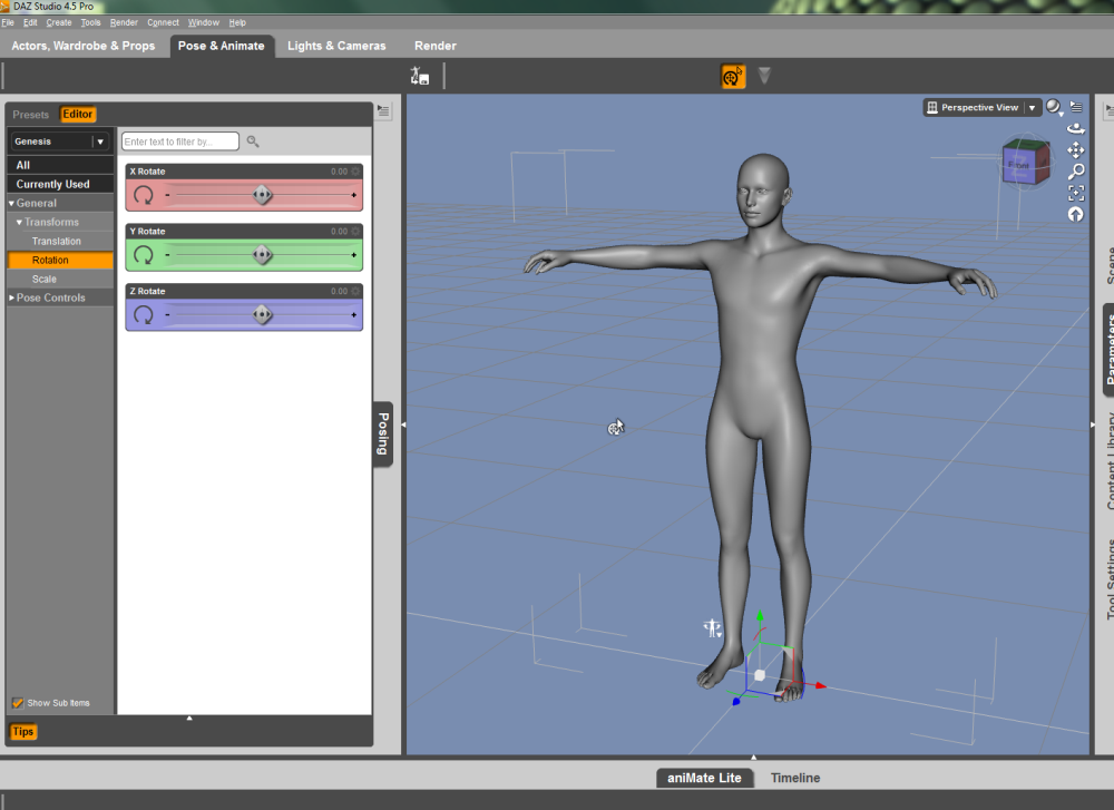
i then decided to model the figures in DAZ Studio 4, which starts with
a template body named genesis:
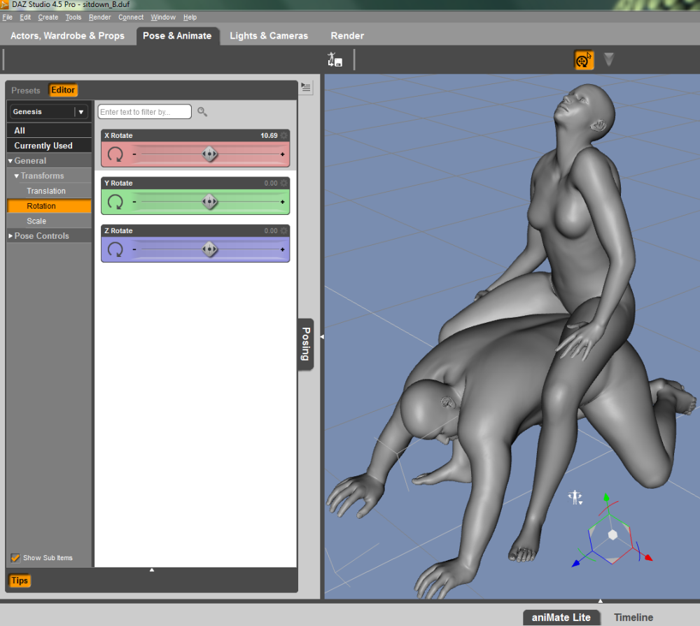
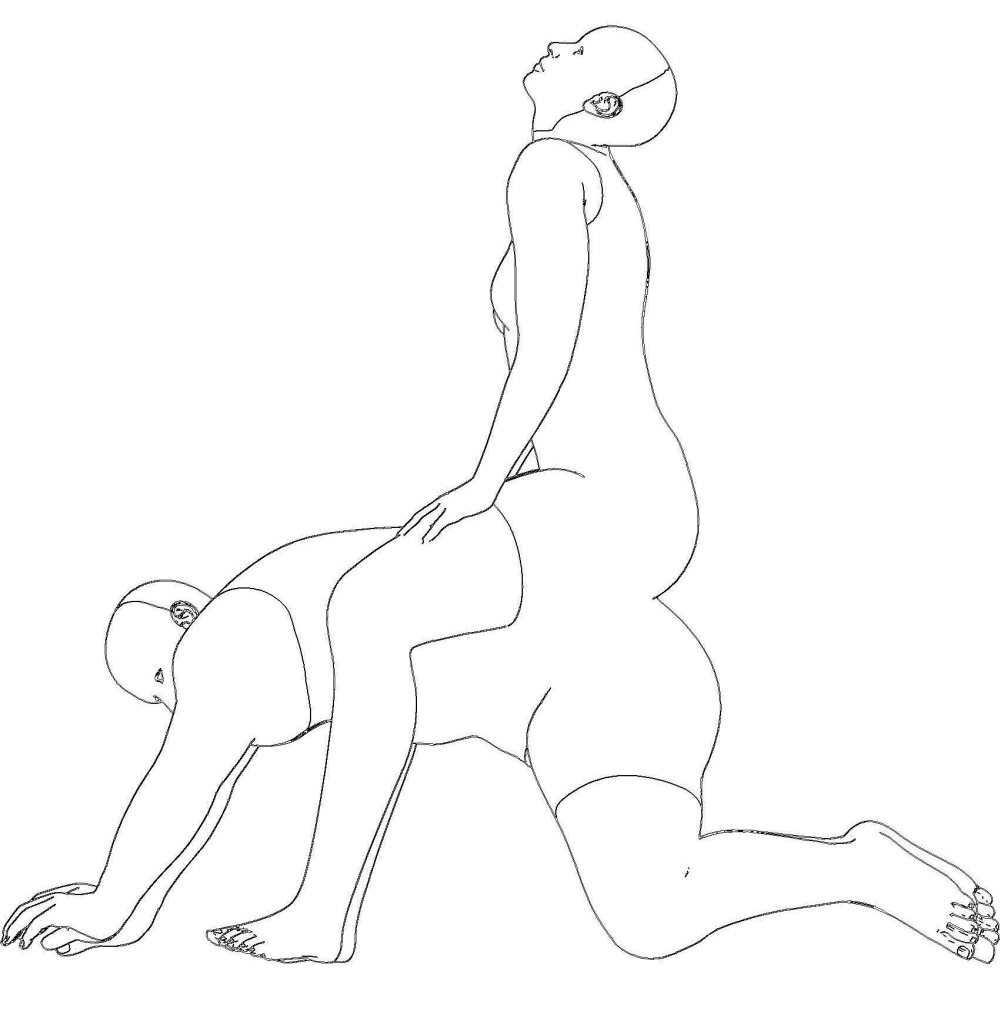
i added another body and posed them to get a posture that would allow
a relatively comfort sitting, something likje this:
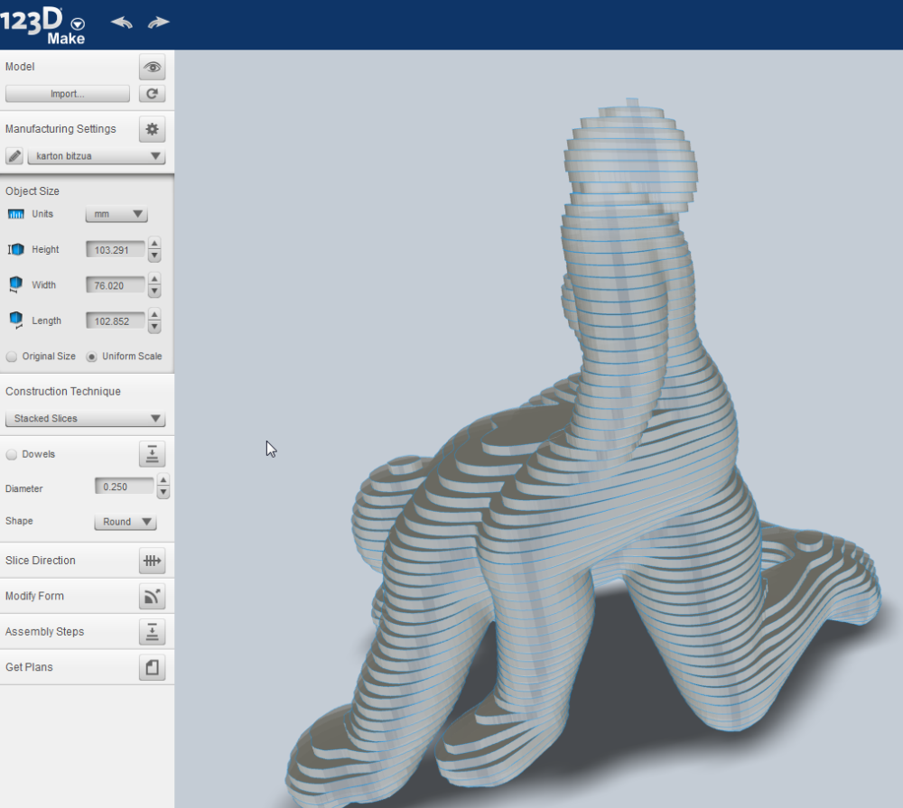
i imported the figures into 123D Make, after some fixing in Rhino,
and under construction technique i chose stacked slices:
i decide to make first a scaled model, 1:10, in cardboard, to check the design
in a physical form:
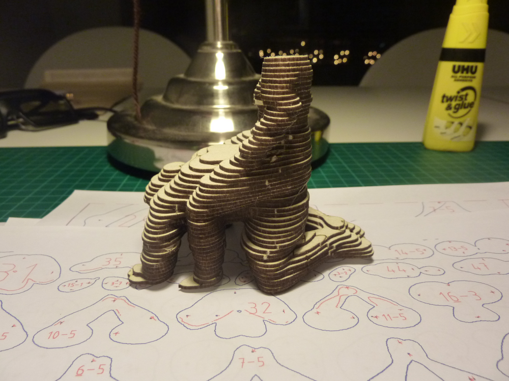
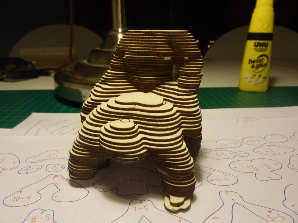
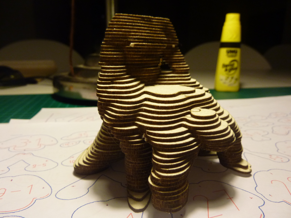
although i liked the design,it had some flaws that convinced me to choose another direction: it was too wasteful in terms of material (it required between 4-6 plywood boards of 1200x2400mm) and maybe too strong or "kinky" in terms of concept.
this time i went for a more economic and neutral concept,
a new table design for our workshop:
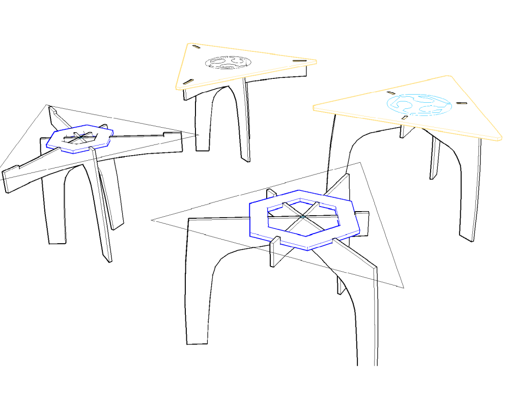
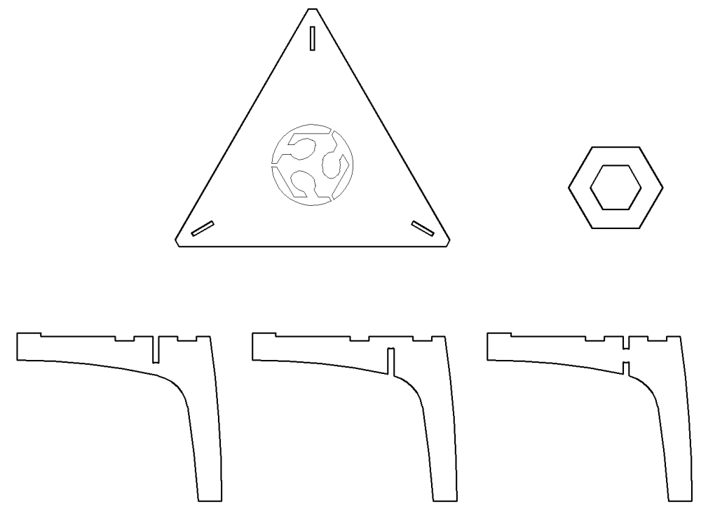
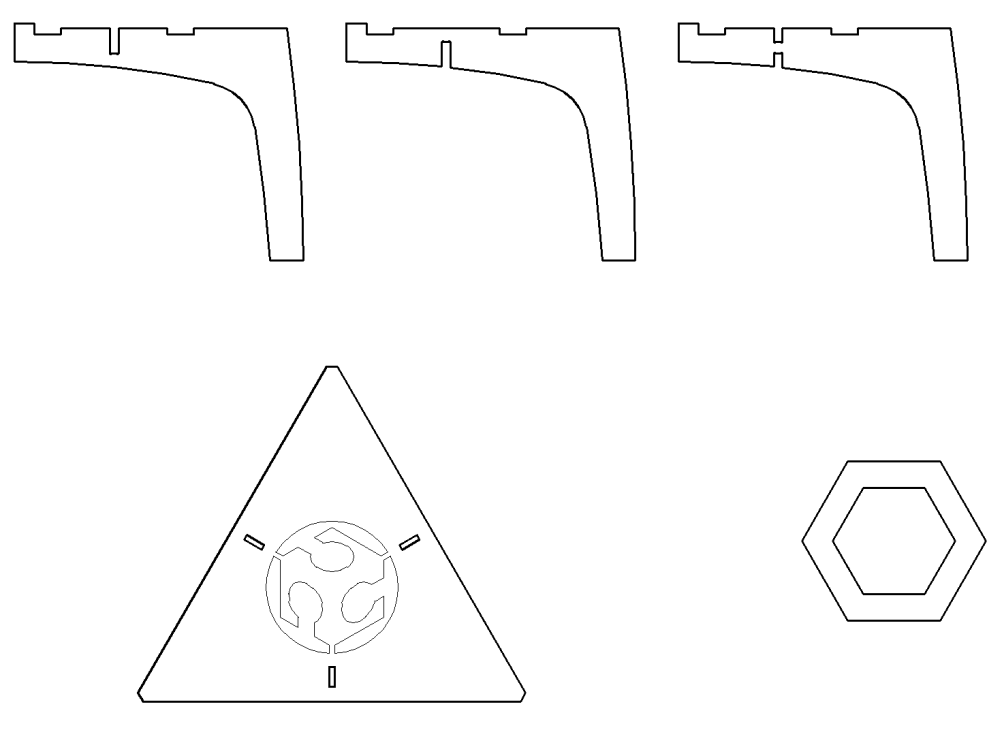
as one can see, i designed 2 options, the first one with the legs
more centrically positioned, but probably less stable.
the second one with the legs more spaced out.
both designs are similar in the manner in which the 3 legs interlock
with each other, which is NOT in a 90 degrees angle, PLUS
3 legs interlock at the same place, significantly weakening this spot.
i hope the reinforcing HEX above will take care of that.
in the next batch of pictures you an see the results of a scale model i did with cardboard cut in the laser cutter.
i don't like the design at all )-:
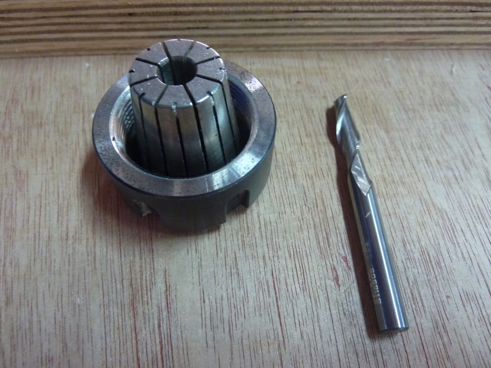
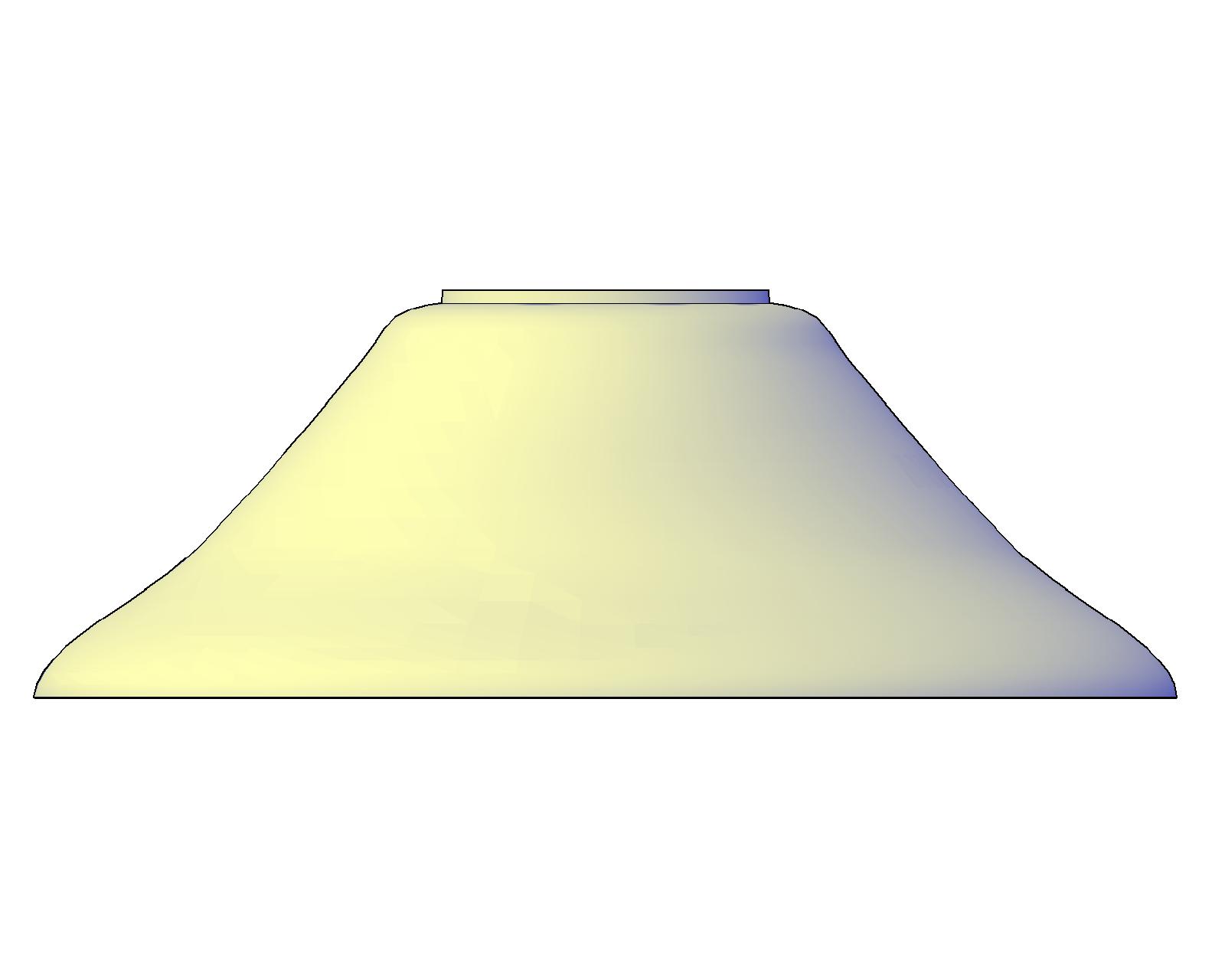
the first one was too steep, would get in the way of the mill's collet.
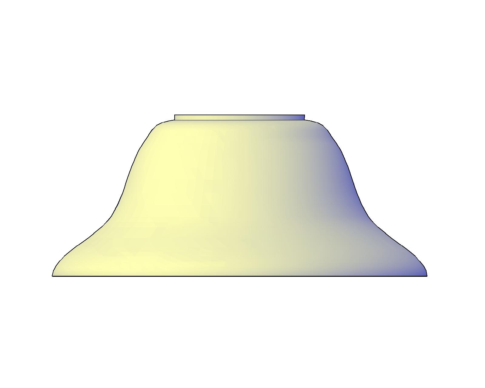
this one will do!
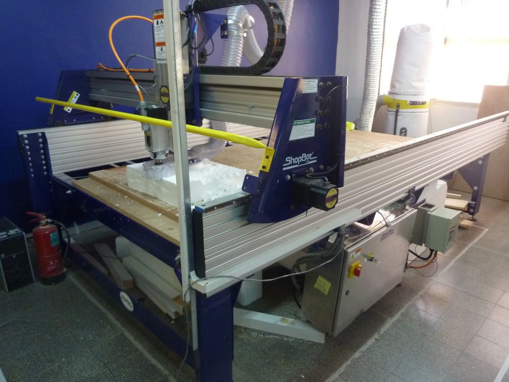
lets start with a video that shows just how close the collet gets to the material.
you must take that into account when designing the model!
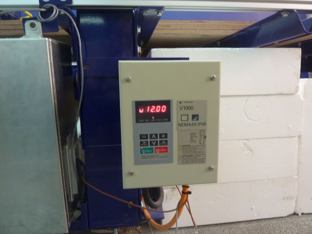
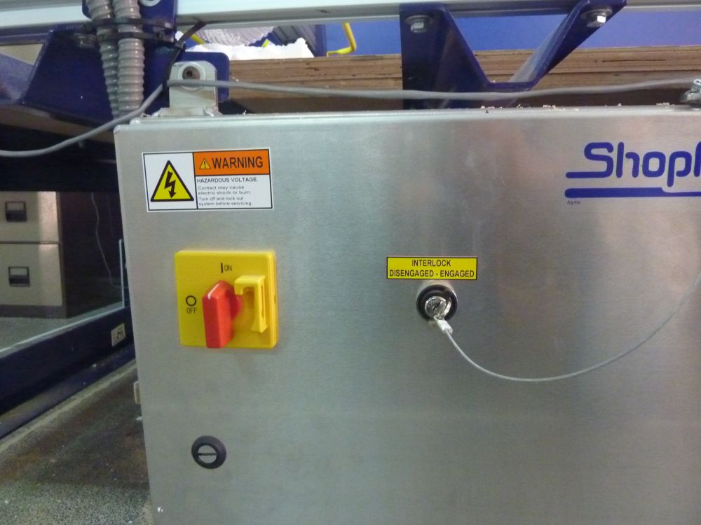
this is the control box. you can see the speed of the spindle, 12,000 rpm.
here you turn it ON, both the red knob and the key.
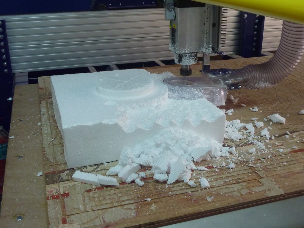
i didn't take into account that the pvc cover of the vacuum dust collector would get so much in the way.
eventually i had to dismantle it, and most of the milling was done without the benefit of automatic dust collection.
lets say that i had a LOT of cleaning to do afterwards.
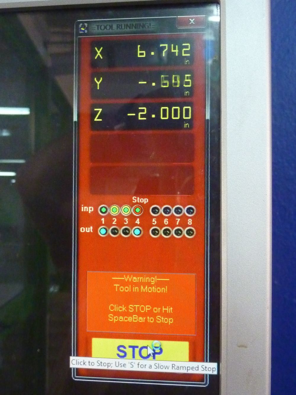
i hit the STOP button to stop the machine before taking the pvc cover apart, of course.
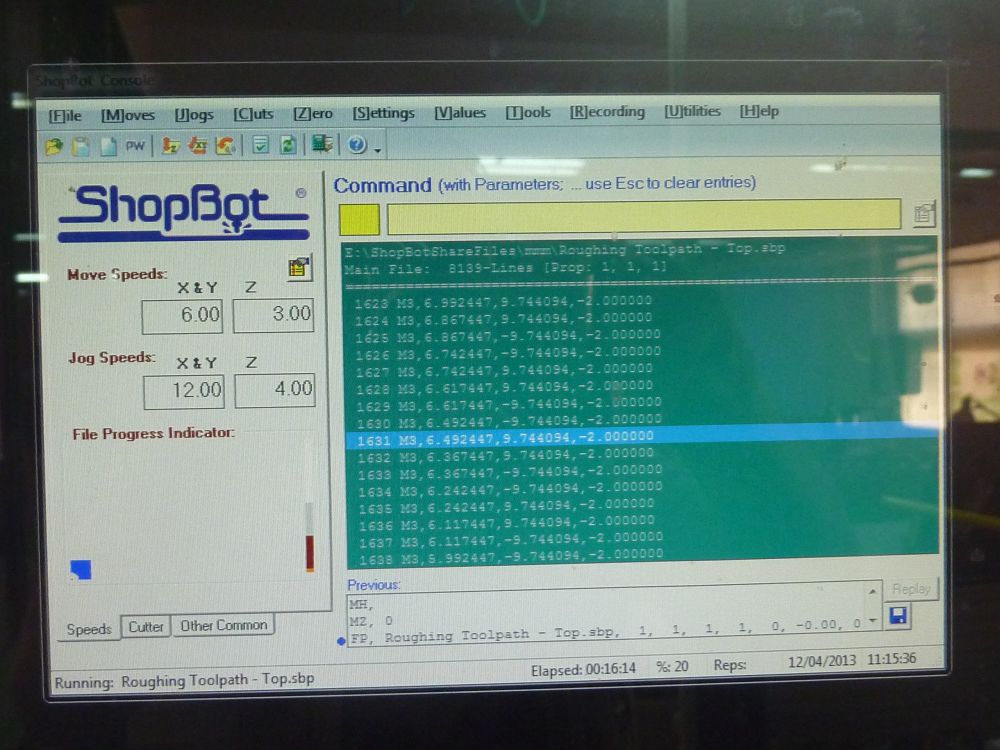
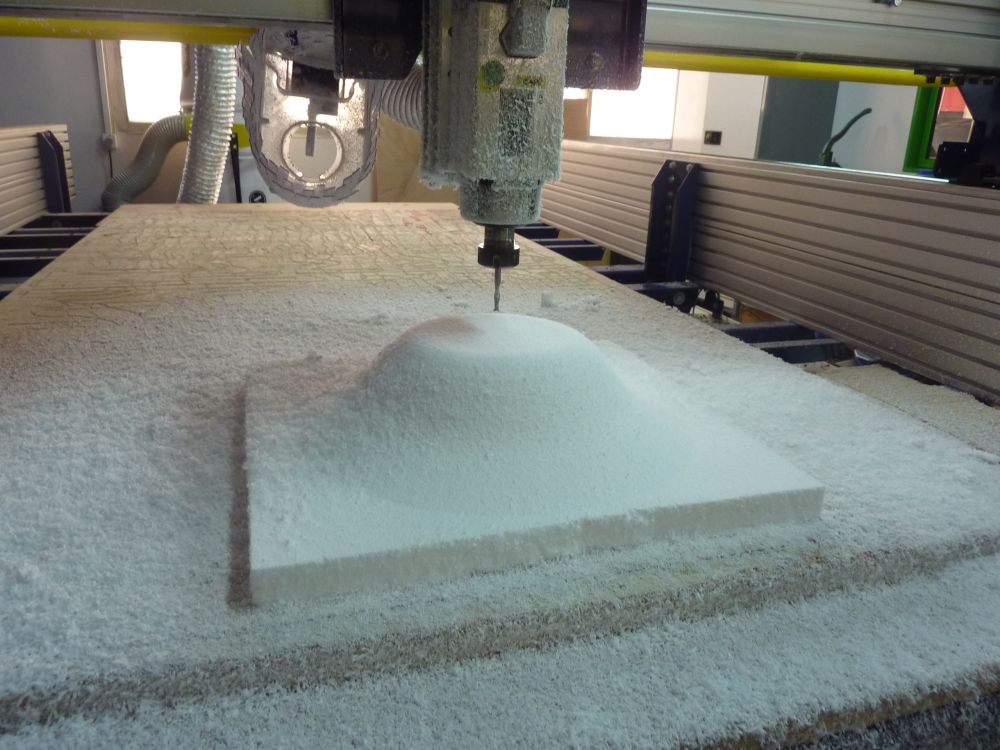
the ROUGH phase was done in relatively big steps, to make the job quicker.
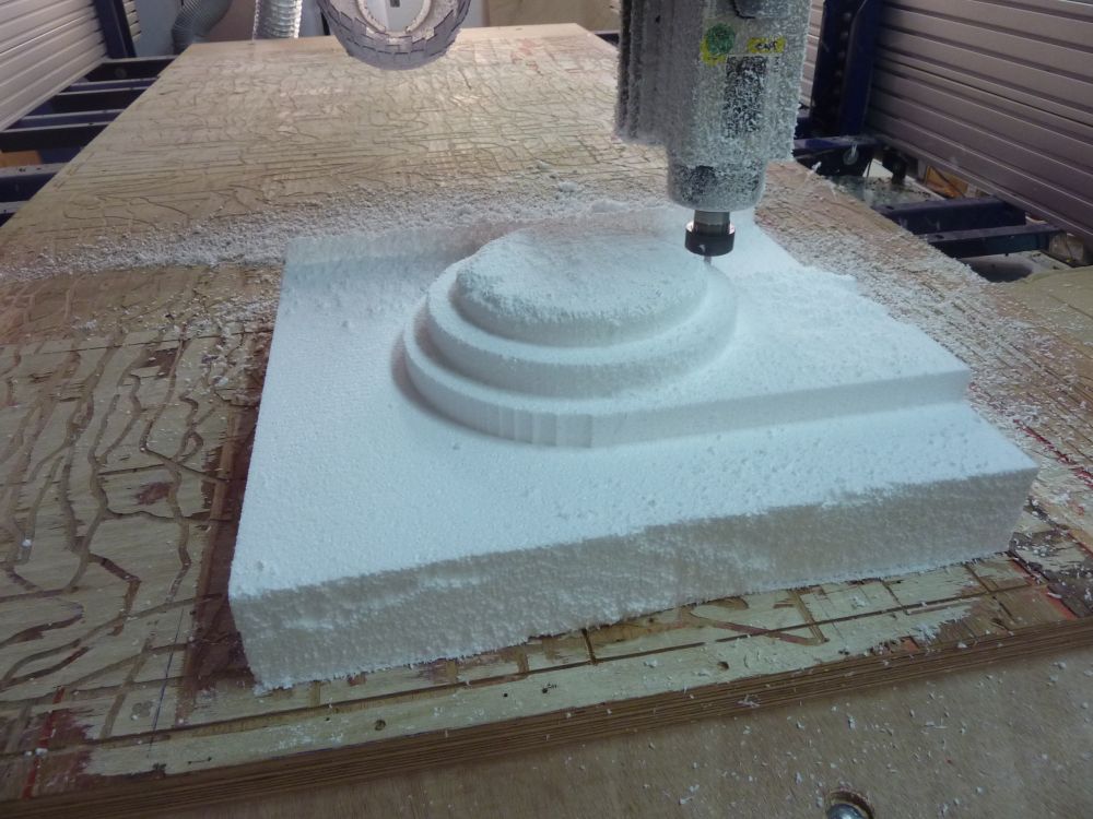
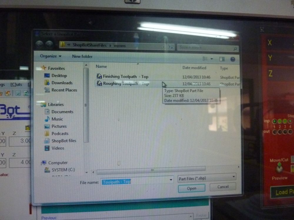
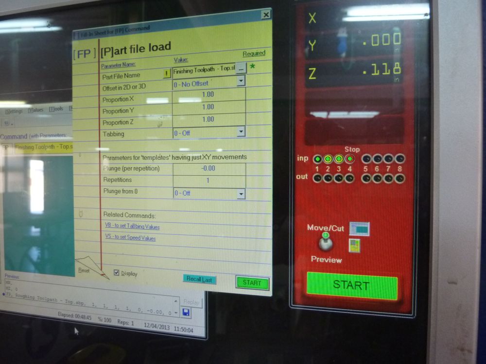
after the ROUGH path is done, you load and run the FINISHING path file.
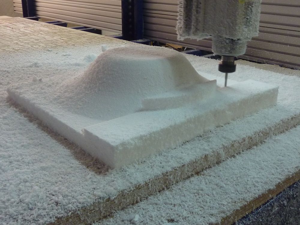
you always have to take apart and clean the collet after a job is finished.
