week 6, feb 27
weekly assignment: redesign a PCB schematics and board
the tools
hardware:the milling will be done with our CNC milling machine which is not a modella like everyone elses.
soldering, etc.
software:
for designing the PCB schematics and board i used EAGLE
for obtaining the GCODE i used the FAB MODULES
for sending the gcode to the milling machine we have LinuxCNC
designing
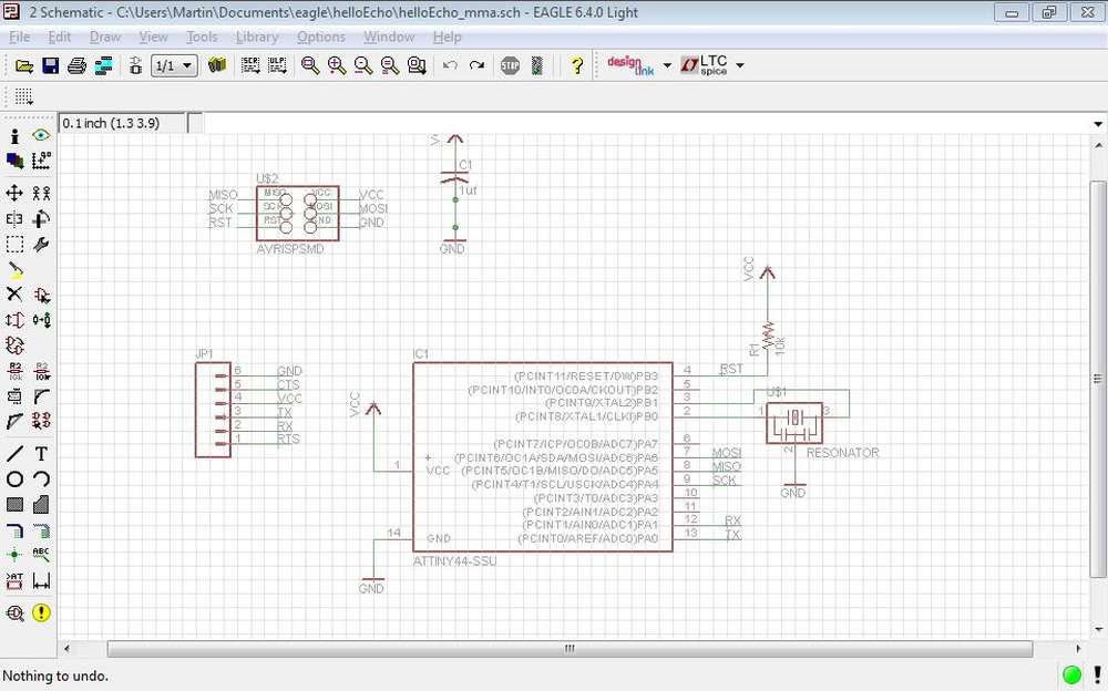
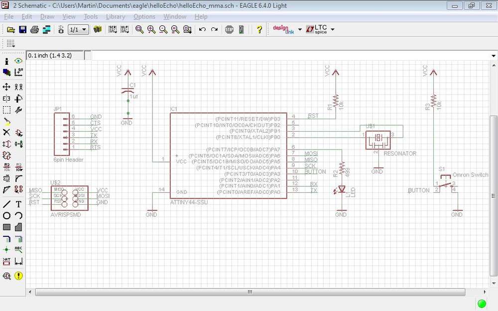
the assignment was to redraw the "echo hello-world board", add (at least) a button and LED (with current-limiting resistor), check the design rules, and make it.i started with a predrawn basic design of the board, as suggested in the providence's fablab tutorial here
this is the basic schematics that was already predrawn, opened in in EAGLE:
 larger image
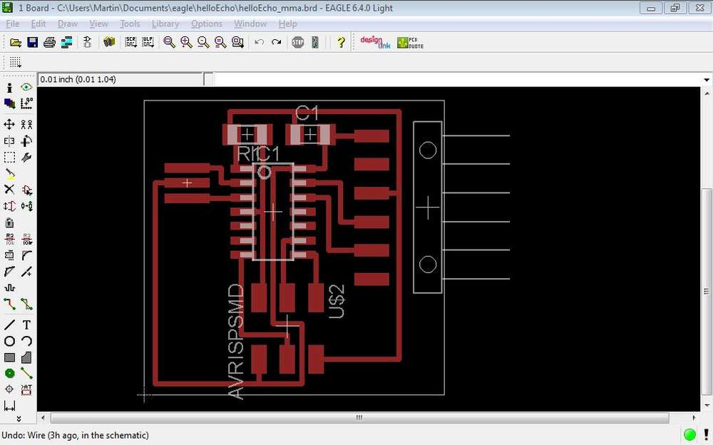
and the predesigned basic board
 larger image
the predesign came with the following already predrawn:
to that i had to add:
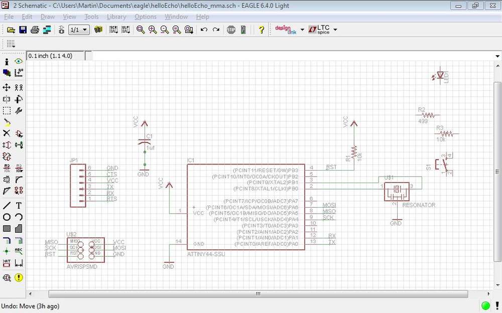 larger image
and this is how it looks after adding the LED, button and re sistors:
 larger image
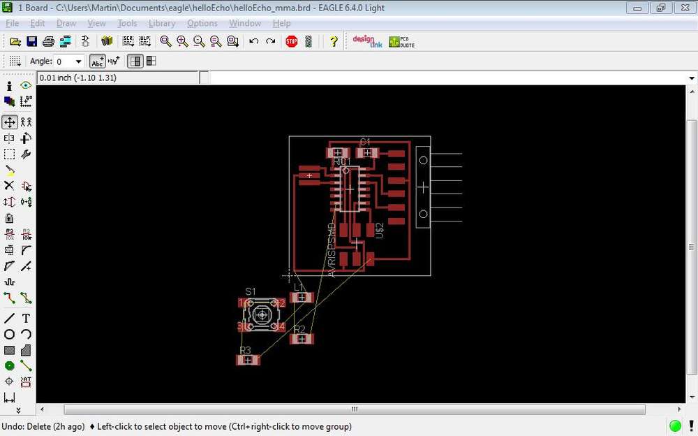
this is what the board layout looked in EAGLE after throwing in the new components:
 larger image
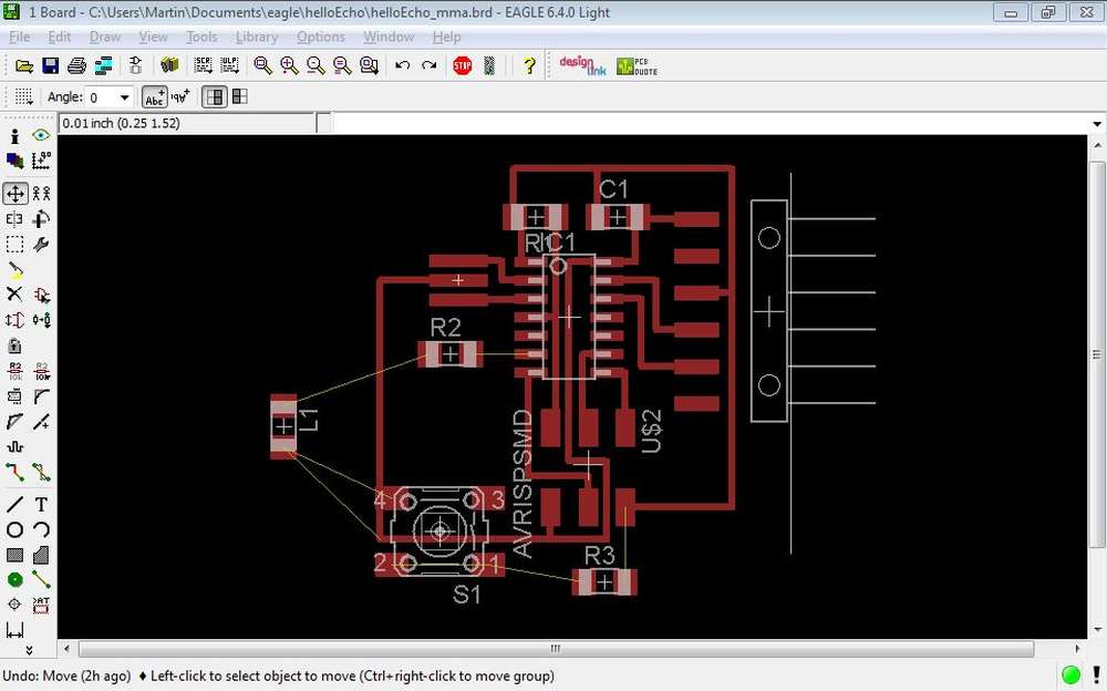
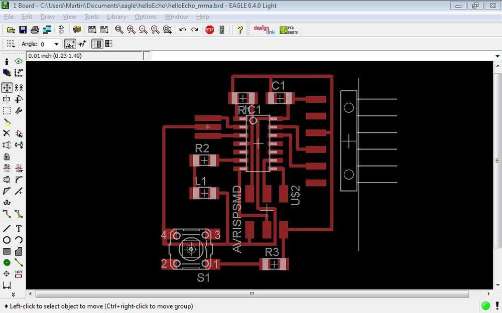
the hardest part was to manually design the board layout without crossing wires.
 larger image
 larger image
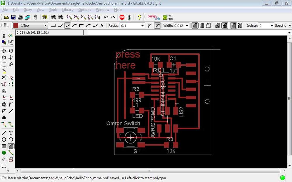
this is the result:
 larger image
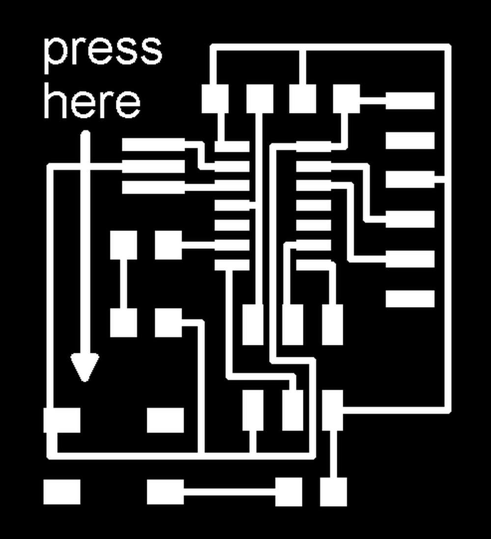
i wanted to add an arrow that pointed to the button, and decided to draw the triangle in a graphics program afterwards.
this is the resulting PNG export of the board layout:
 larger image
for the graphic editing i used a very simple viewer that has basic editing features ando also that allows you to crop, resize etc. it's named IRFANVIEW and is freeware.
with that i added the little triangle of the arrow, cropped the image and also created the the miiling out image:

fab modules
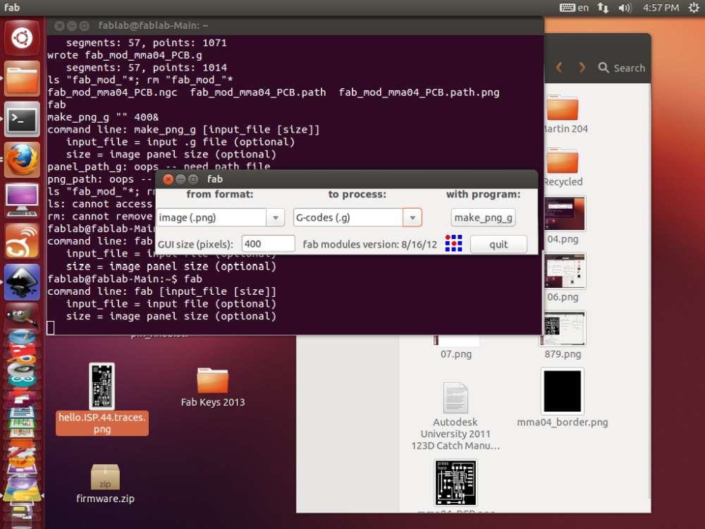
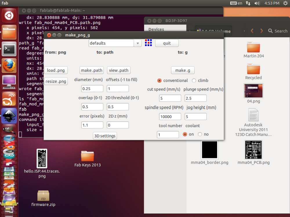
the gcode generation in fabmodules was very simple, the process is shown below: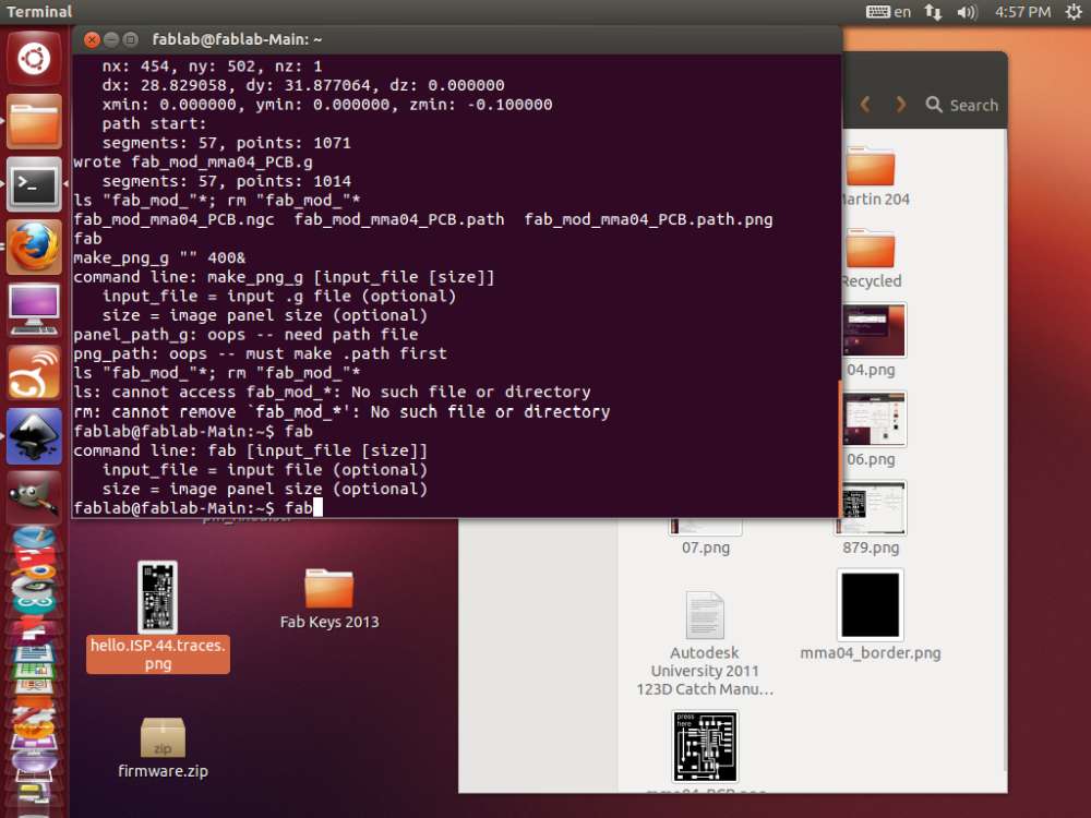 larger image
 larger image
 larger image
in the window below you have to chose either mill traces (1/64) or cut out board (1/32).
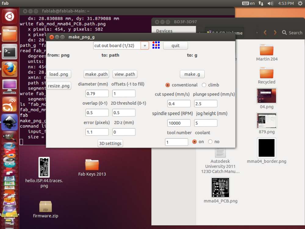 larger image
in the window below we changed the offset from the default of 4 to 2.
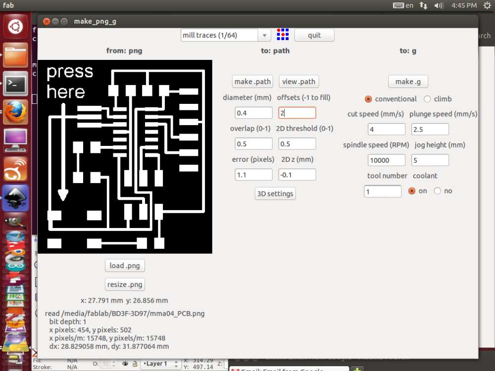 larger image
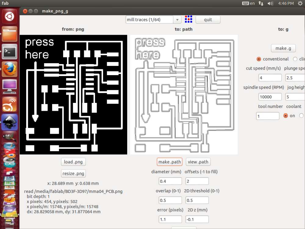 larger image
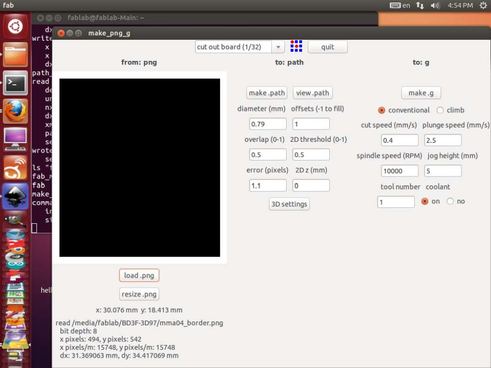 larger image
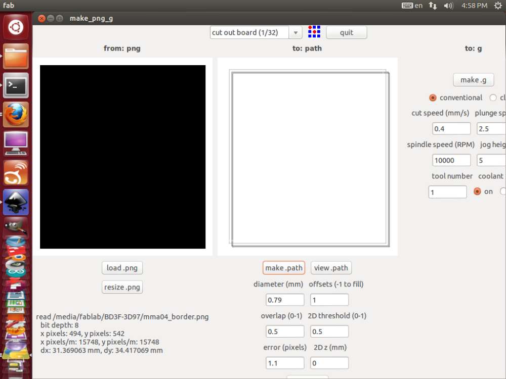 larger image
in the window below you can see the output gcode file:
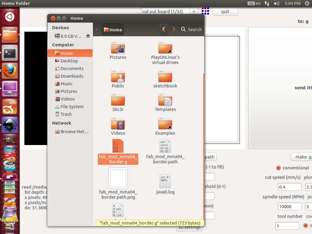 larger image
the filename extension of g has to be changed to ngc before loading the milling software:
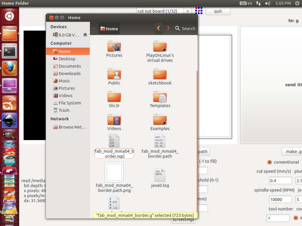 larger image
below you can see the actual tracing files that fabmodules generated:
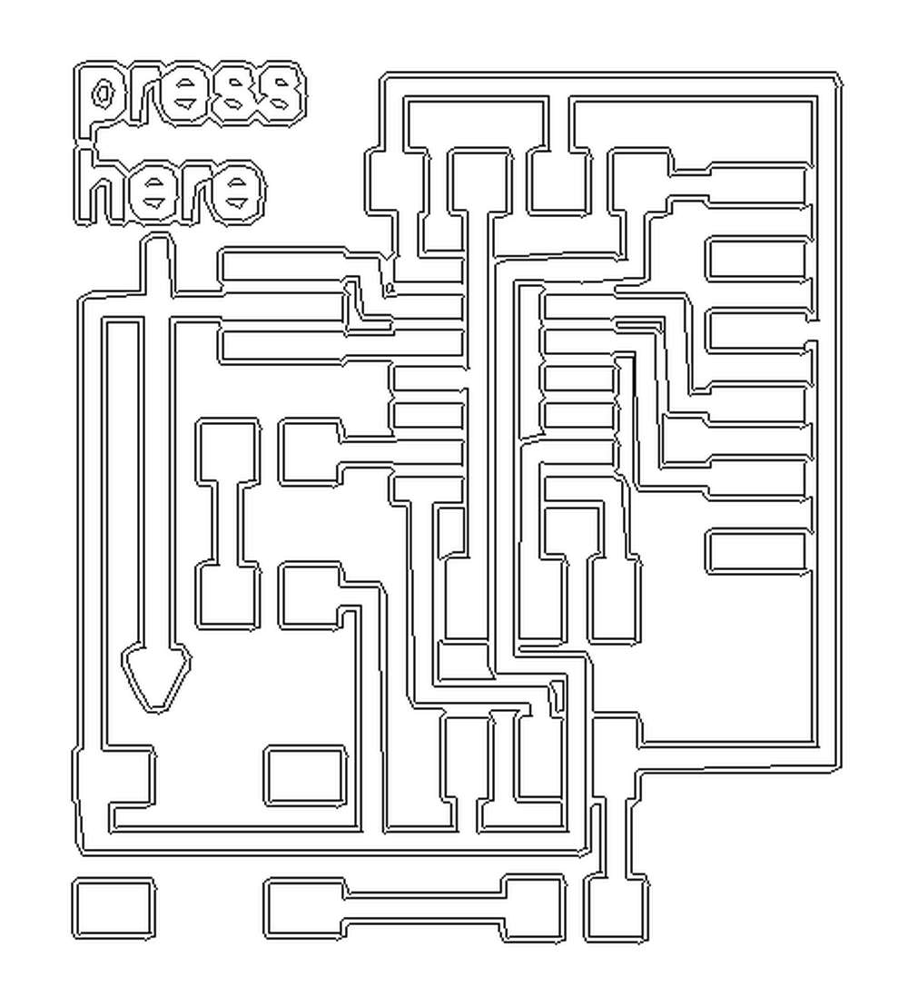 larger image
 larger image
sending to the CNC
after starting EMC2 (also called LinuxCNC) we choose the Sherline3Axis_mm machine, see below: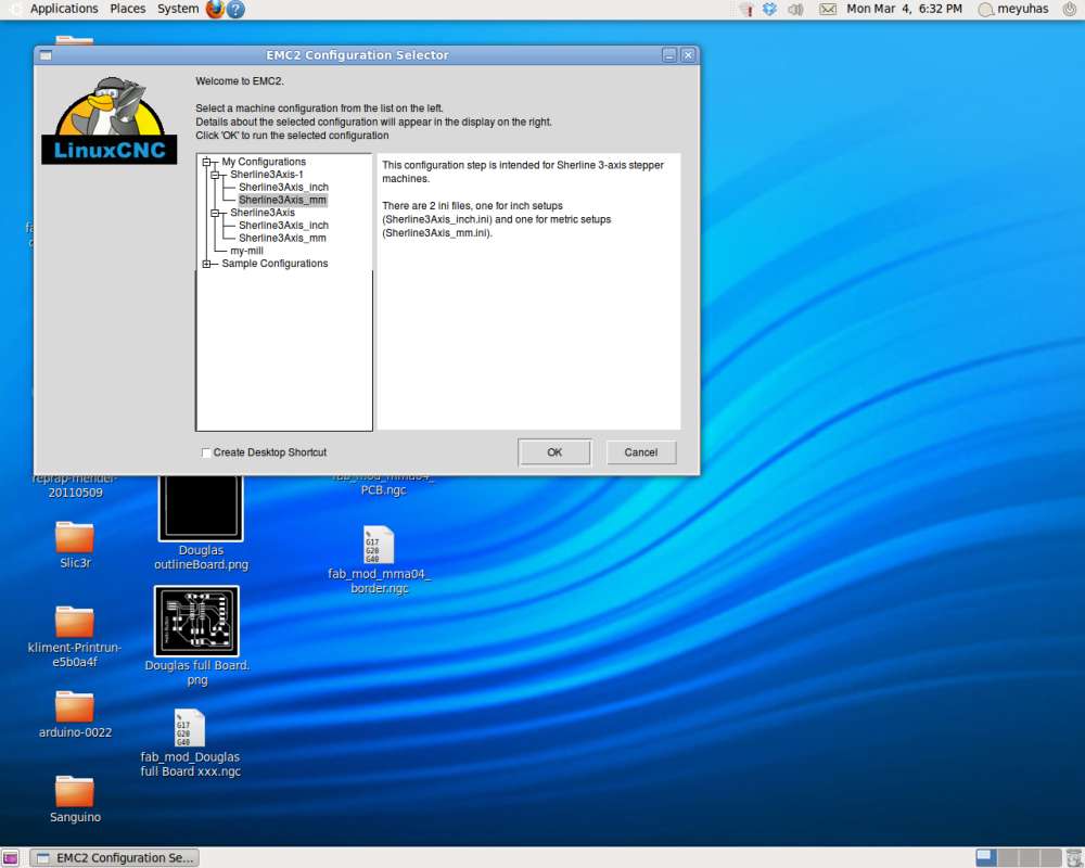 larger image
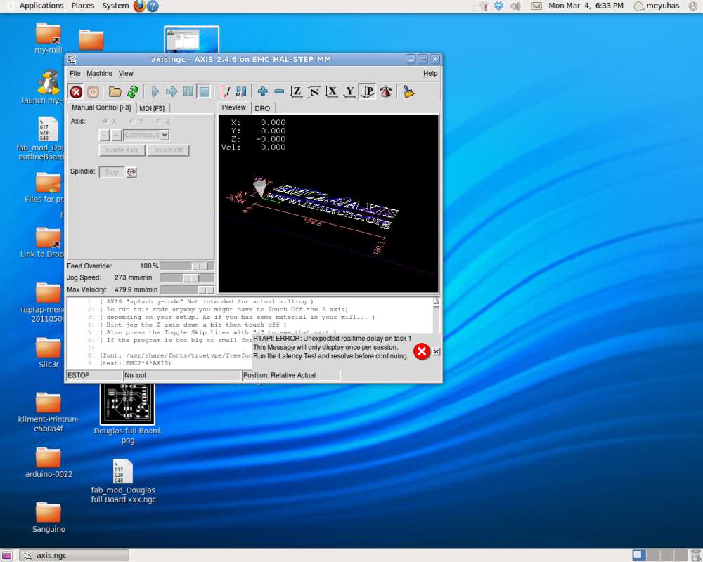
at first the speed were set too high for our machine (Jog Speed and Max Veloxity), so we lower them to 93 mm/min both, see below:
 larger image
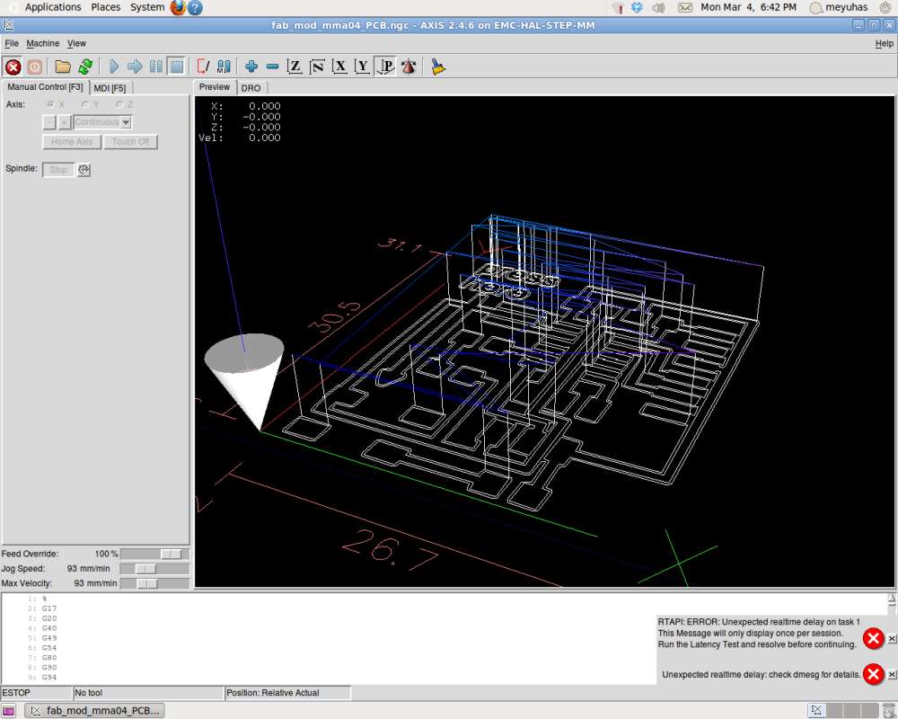
below you can see how the gcode looks when loaded
 larger image
after loading the file and placing the board on the machine, you have to set the "home axis" point for each of the 3 axes.
pay extra attention and care to the z axis homing beacuse you can easily break the tip of your bit! see below:
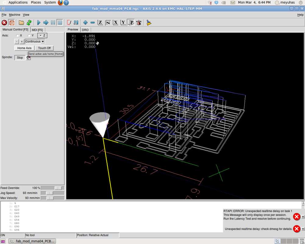 larger image
after homing the axes and spinning the spindle to the max, you can press on the PLAY button, and see on the screen the actual work of the machine, see below:
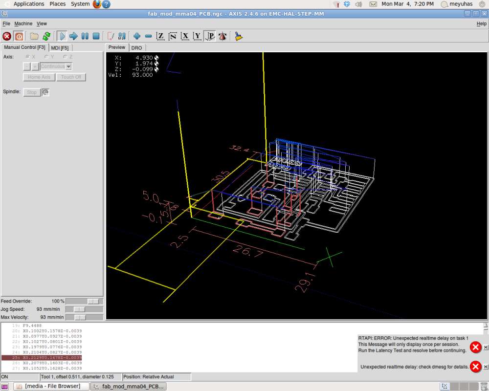 larger image
milling
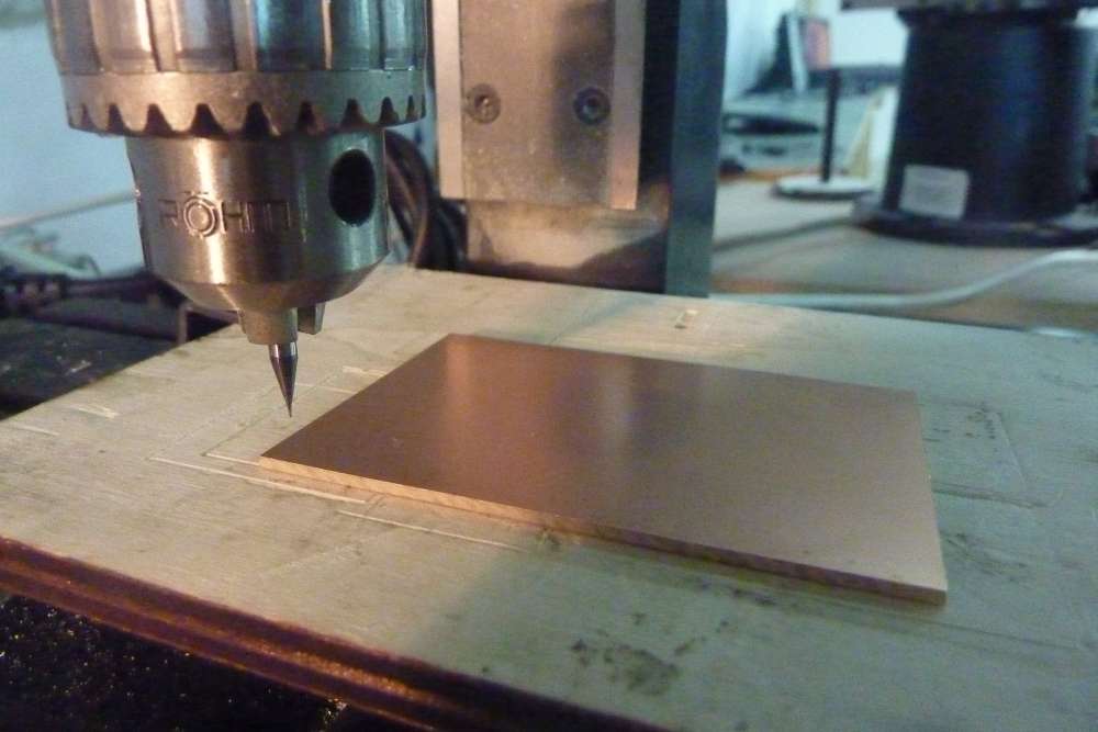
here you can see the hardware at work!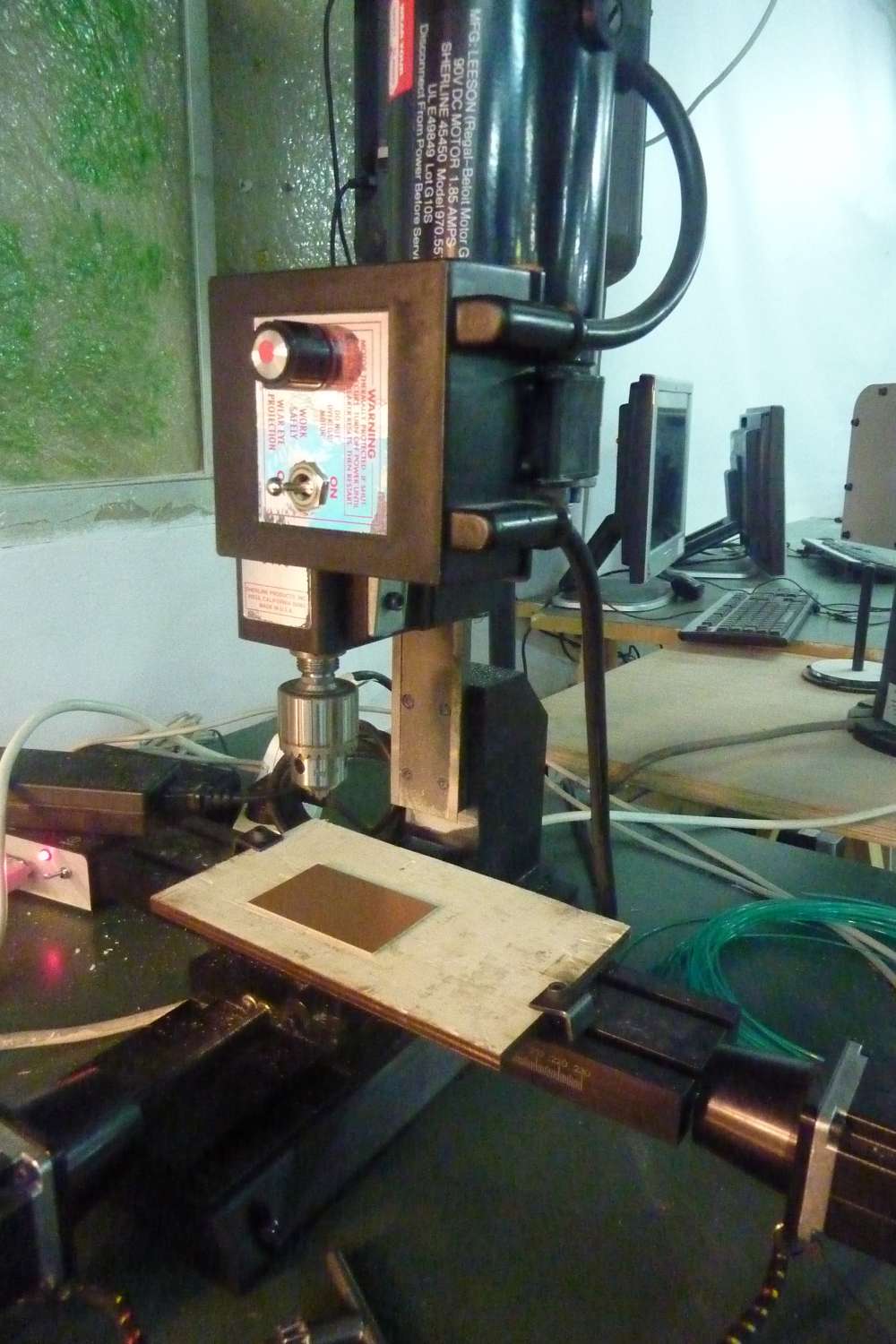 larger image
 larger image
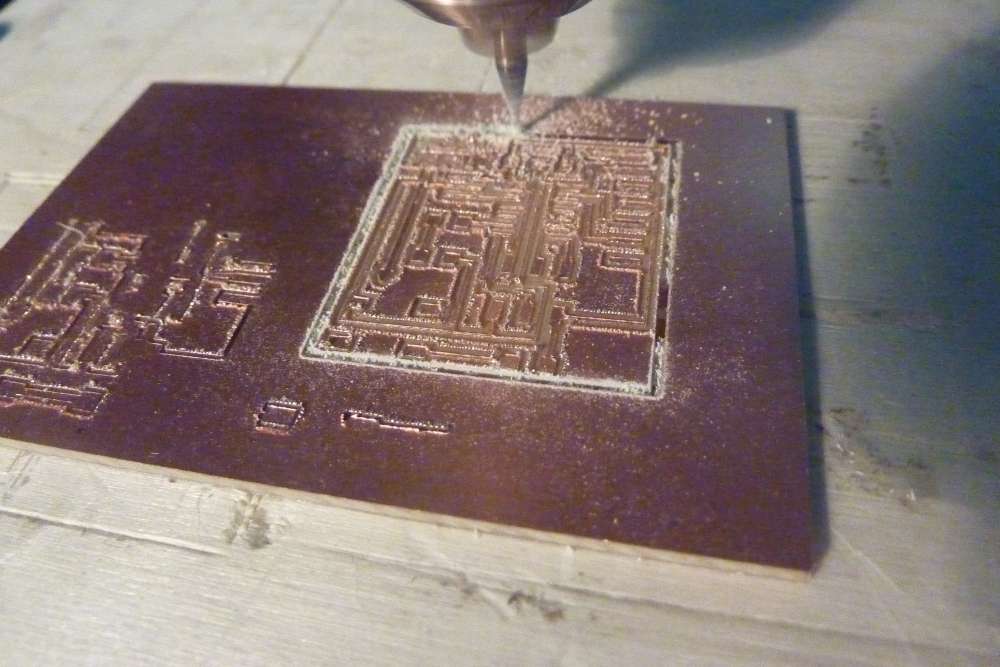 larger image
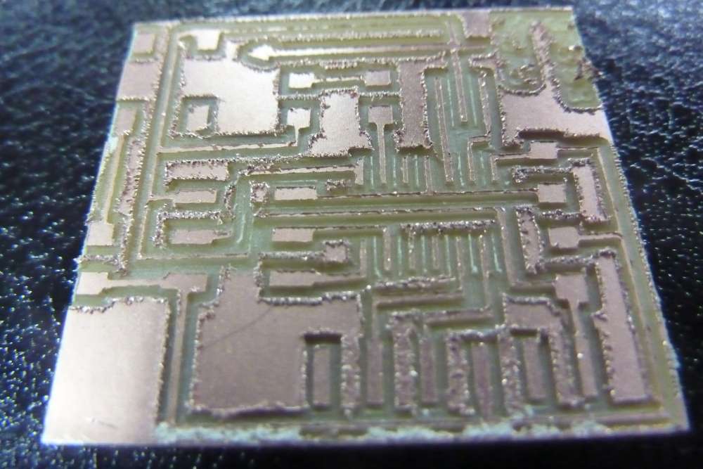 larger image
problems
after the milling was done, and managing to break only one bit in the process(!), i checked the board and and it didn't look so good. i deburred a little, but was afraid to overdo it since the wires were so flimsy and thin at some points.here you can see the freshly milled PCB alongside it's image as designed in eagle.
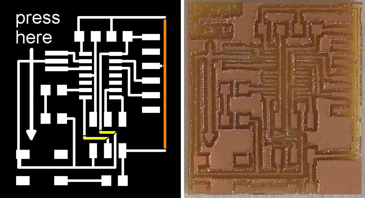 larger image
the colored lines are either completely disconected or almost so!
when i come to the lab this wendsday i will try to mill a new one, paying extra attention to the parameters in the fabmodules and EMC2.
another thing learned: if you want text on the board, you have to make sure the width of the letter lines is wide enough, my text doesn't show at all!.
second attempt
i had another go with a small update in the FABMODULE parameters: we changed the overlap from 0.5 to 0.7 which seems to better suit to our SHERLINE CNC.i also made a couple of cosmetic changes to the board design, editing the contour and replacing the invisible text with a bigger graphical sign.
one can see the result here:
 larger image
no doubut it looks way better, but still the same two wires as before didn't make it, and another wire i killed while deburring, see here:
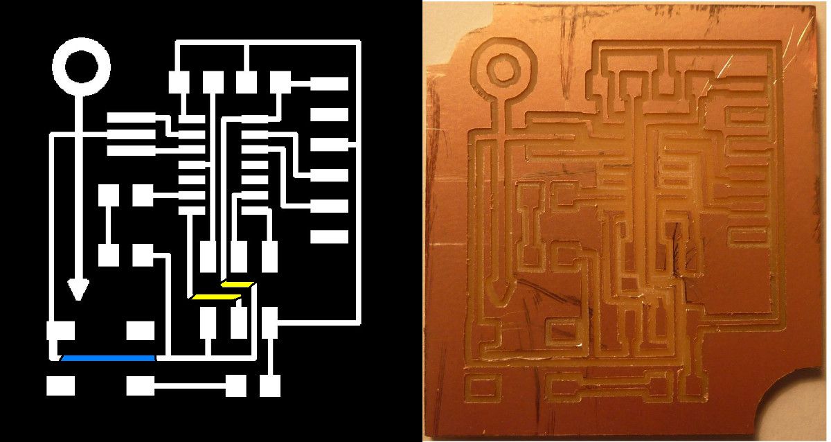 larger image
the yellow ones: already dead after milling )-:
the blue one: killed while deburring ))-:
