 2013 2013
the goal was to get some experience with PCB fabrication. that includes starting from an
already working electronics circuit schematics and doing the following:
the assignment included PCB production and assembly. the design of the circuit itself was already partially given, but we still had to complete it.
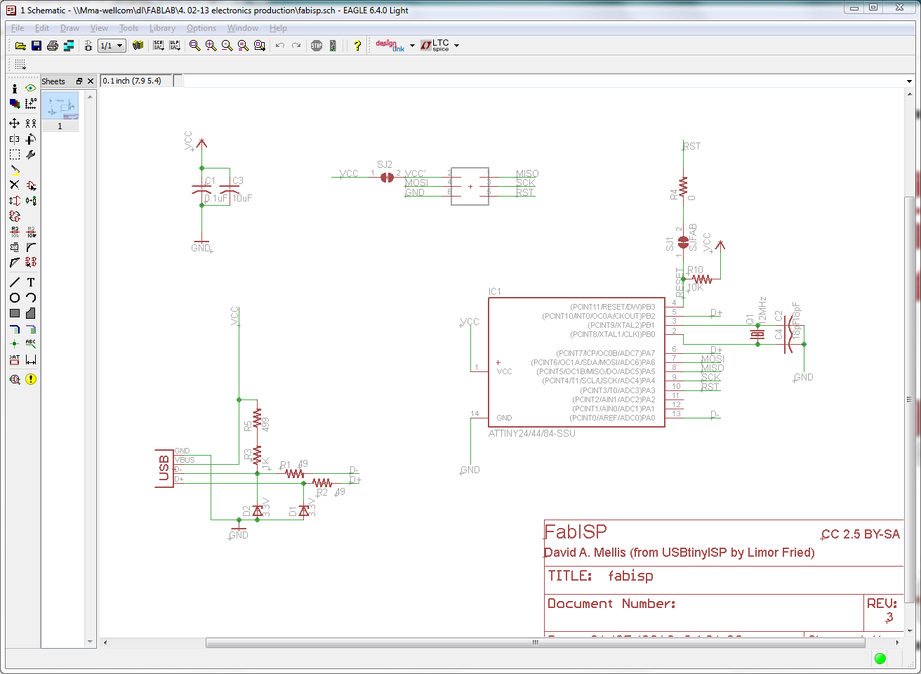
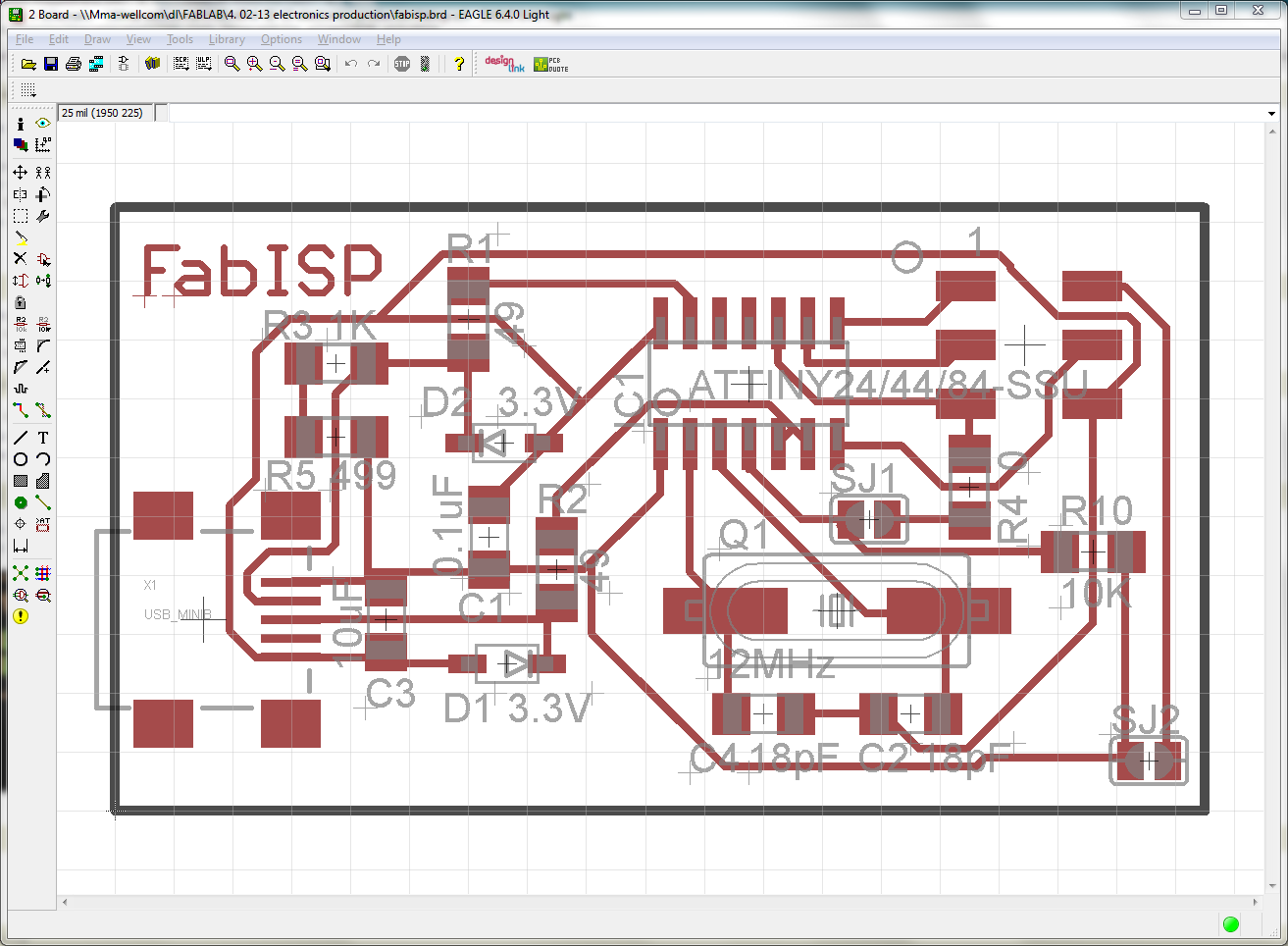
the FabISP board is an in-circuit programmer for AVR microcontrollers.
this board will enable us to program the microcontrollers on the other boards we make during the fabacademy.
we used a circuit design by David Mellis and updated by Neil.
the original circuit schematics and board layout show in EAGLE like this:
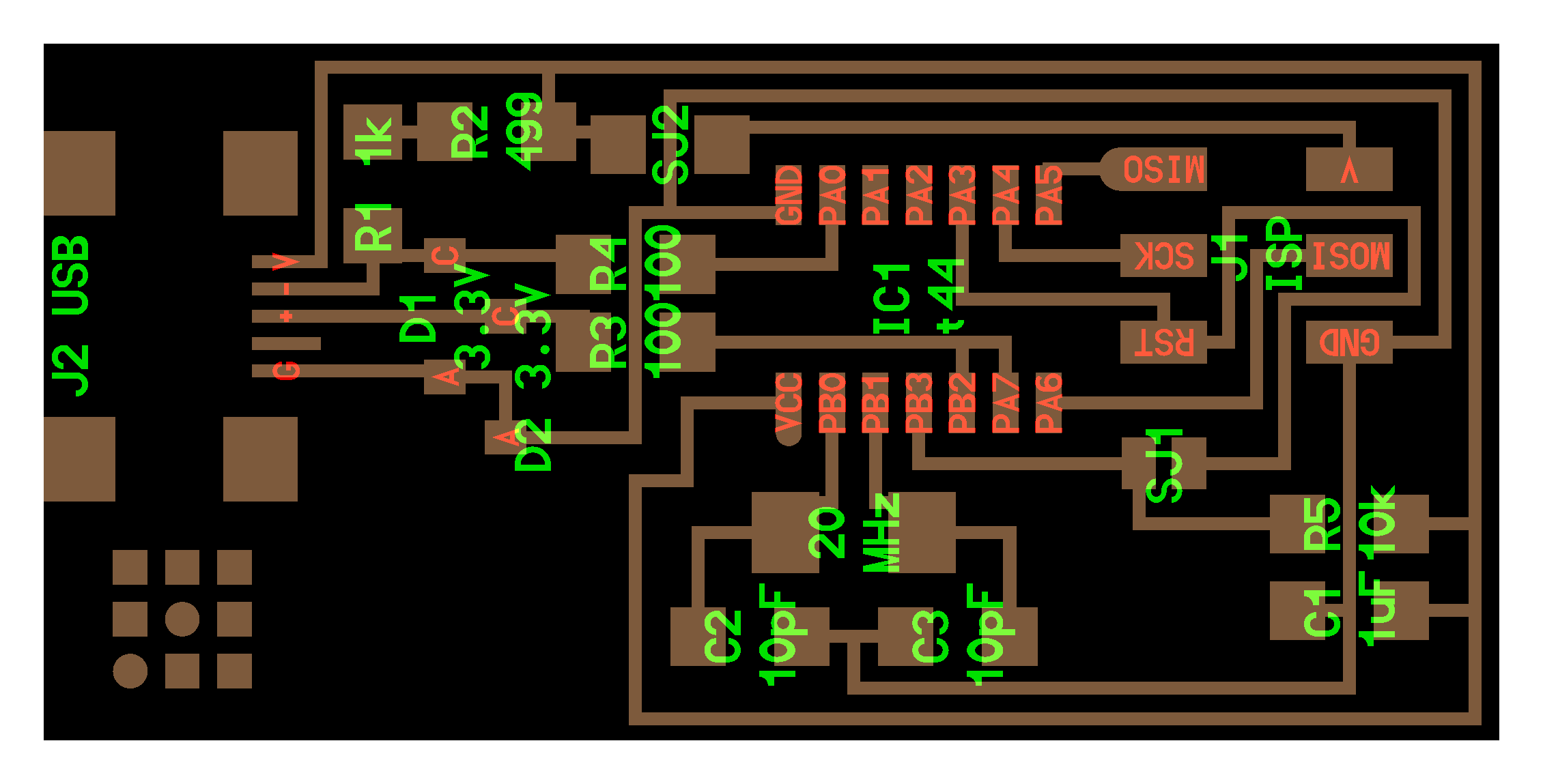
the actual tracing files of the david mellis design we used were a little bit different:

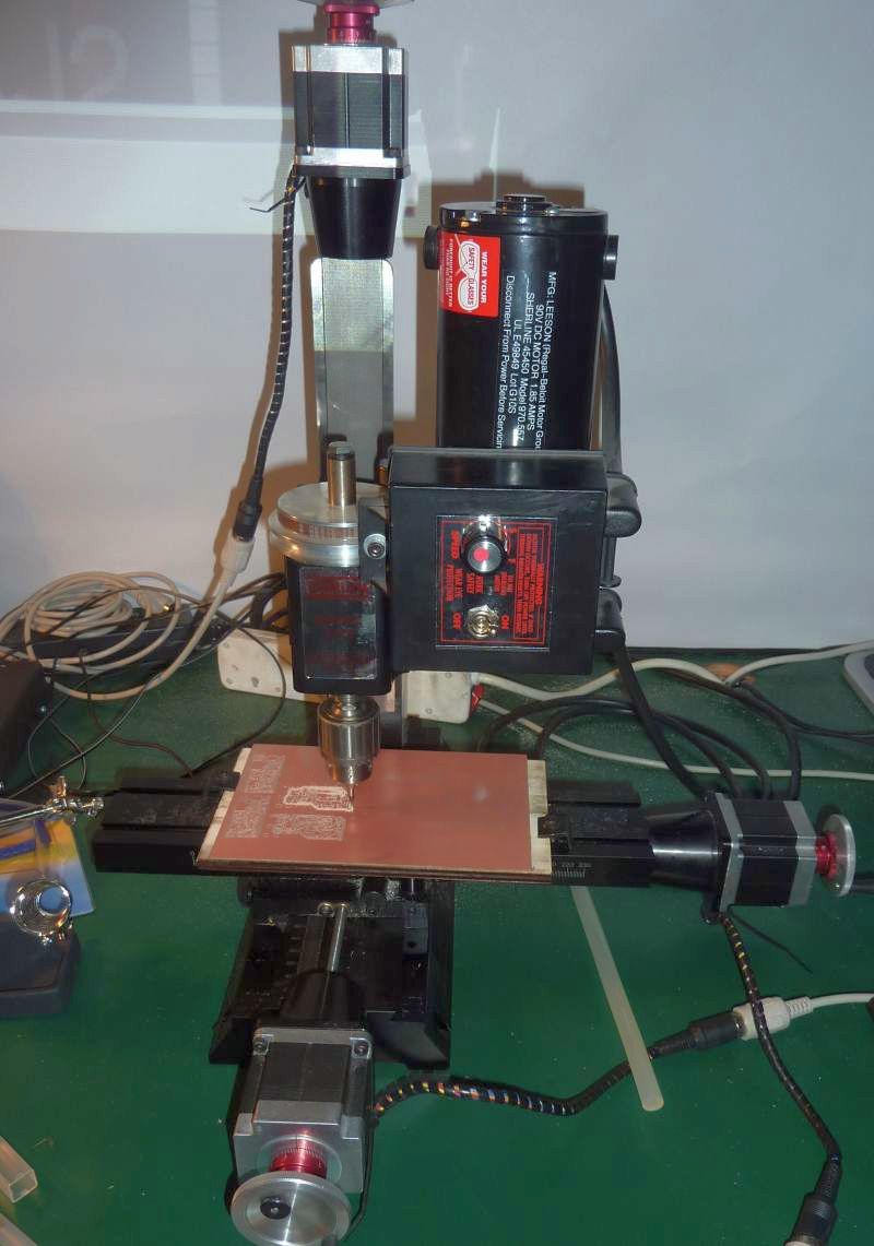
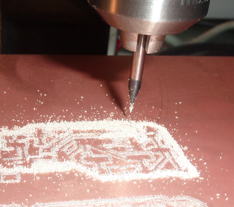
the milling machine needs an file with milling instructions written in a language called G-Code.
you can generate the G-Code within the EAGLE program by adding an extension to the software named "pcb-gcode".
another option is to export an image file from EAGLE and import it into the Fab Modules, which is what i did.
to do that switch to the BOARD view, and turn off all layers except TOP, then go to FILE menu, then EXPORT then IMAGE.
choose a good DPI resolution, like 300 and select MONOCHROME.
take that PNG image files (traces and contour) to a machine that runs LINUX and run the fab modules.
in the fab modules open the PNG file, set the parameters and make the g-code files.
you then have to rename the files extension to NGC for the software that runs the Sherline (EMC2CAM).
first engrave the traces then cut the outline of the board. the board has to be very firmly attached to the machine,
otherwise it WILL move, especially during the cutting phase which puts a lot of pressure on the board!
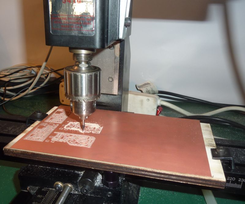
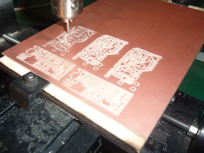
in our case, we traced a batch of pcb's together and had to cut them manually.
this is the tedious part. it took me close to 3-4 hours to solder the board!
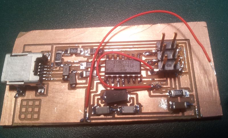
too late i found out that the manual cutting of the board cut on of the peripheral traces, and i had to jumper that with a wire.
another trace become loose and torn during the milling, and that is the reason for the second wire jumper.
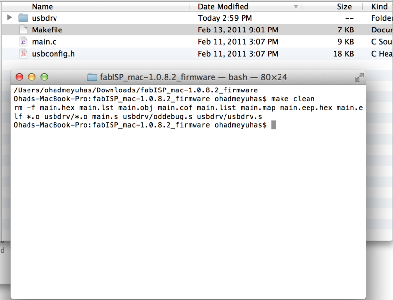
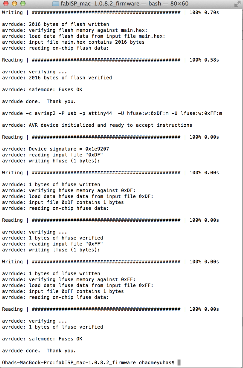
in principle you install WINAVR and do the programming under windows, but my windows 7 32 bit laptop didn't recognized the board.
so i did the programming on a MACBOOK:
the mac has to have AVRDUDE installed.
you have to download the program (the firmware) from the fabacademy assignment,
here
then type: