week 3, feb 6
weekly assignment: design, make, and document a press-fit construction kit
the concept
i wanted to design a geometry based construction kit, kind of a game to engage kids in 3d model construction.it had to have relatively small geometrical pieces, and each piece had to offer several connection possibilities to other pieces.
maybe something like these:

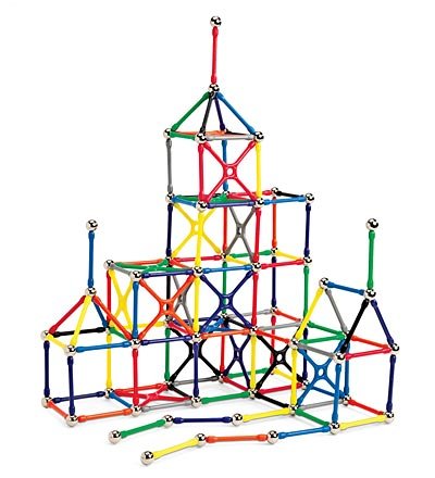
only the connectors instead of magnets would consist of slots and tabs
sketchup
first thing to do was deciding wich software tool to work with. i started fiddling with sketchup, but very quicly came to the conclusion this wasn't the right tool.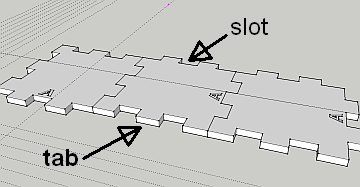 i couldn't figure out a simple way to parametrically change the size of the tabs and the slots.
i knew that that was a must, since i would be changing their sizes while doing the fitting tests.
draftsight
i figured maybe a 2d cad tool would be better, and since i know autocad i wanted to try DRAFTSIGHT, a free (for non-commercial use) 2d drafting tool that remarkabky resembles autocad in its interface and command set.handling parametric needs with "blocks"
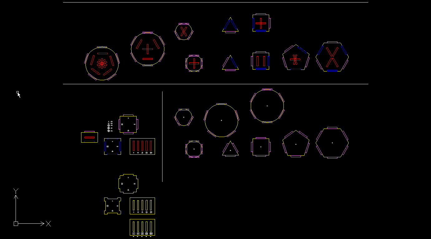
when building the geometry i was pleasantly surprised with the similarity to working with autocad.
the idea was to build the changing parts (the tab and the slot) as "blocks', so that i could easily change all slots and tabs simultaneously.
a "block" in a CAD context is a predefined group of lines that one can place many instances of in a drawing and if needed change every instance at once.
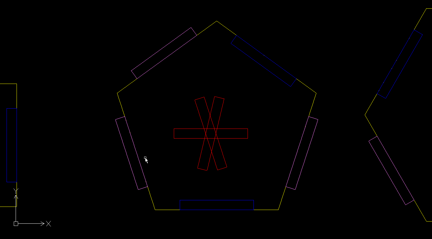
here one can see a closeup of one of the pieces.
the pink rectanles are the tab blocks, the blue ones are slots at the edge of the material, the red ones are slots on the surface of the naterial.
making a "comb"
in order to check the correct relationship between the size of the tabs and that of the slots, so as to ensure a "perfect" fit, i designed a "comb" system, that is a set of tabs and slots with slightly varying sizes. it looked like this: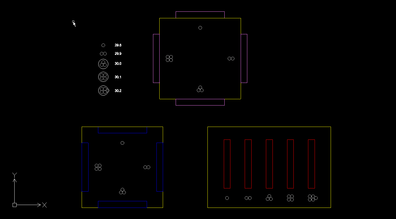
while a REAL comb looks more like this:
but lets forget about that.
merging the blocks into the drawing
in order to export the drawing to the laser cutter, i had to get rid of the blocks (that's called "exploding" them) and do quite a bit of editing to the drawing (trimming lines, deleting lines, converting closed loops to polylines and so on).here one can see how the "comb" looks when ready for exporting:
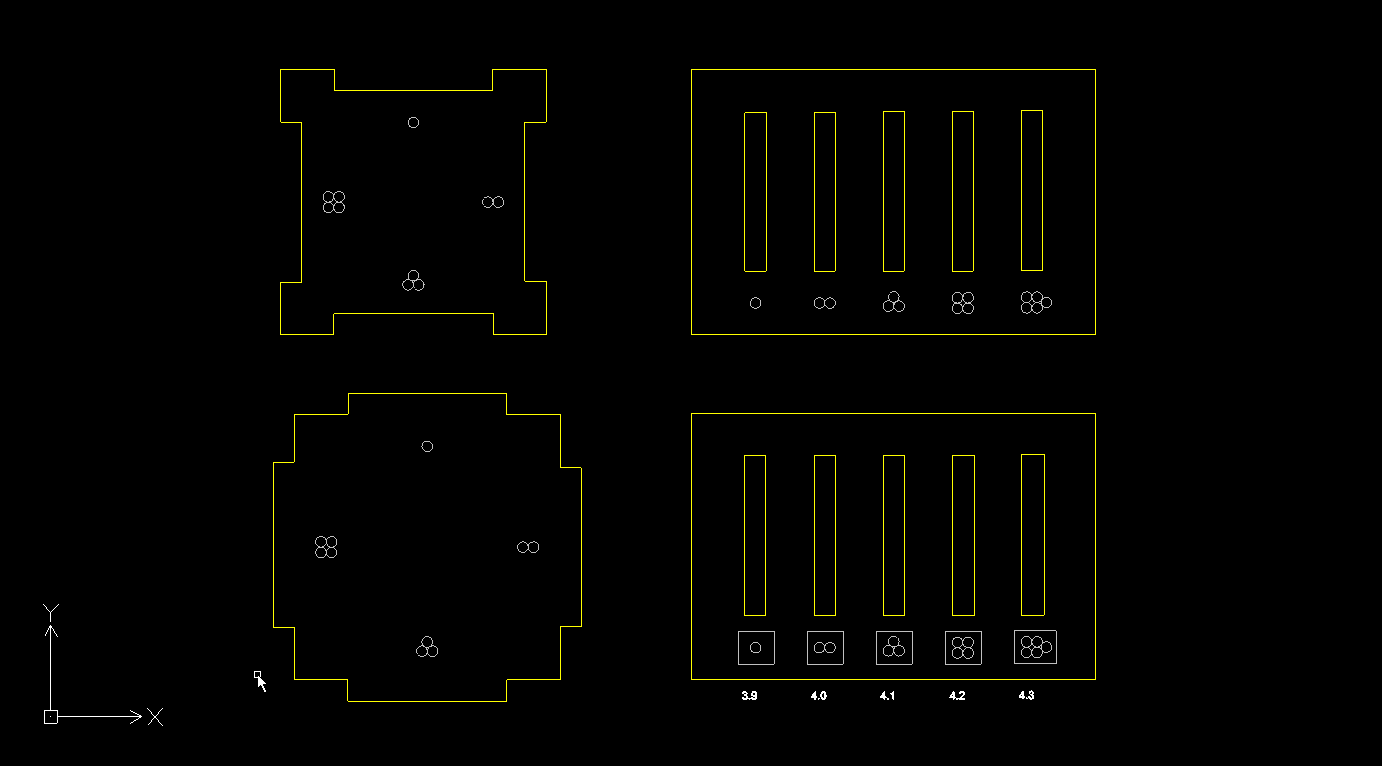
cutting the testing comb
and here we have my very first laser cut tests!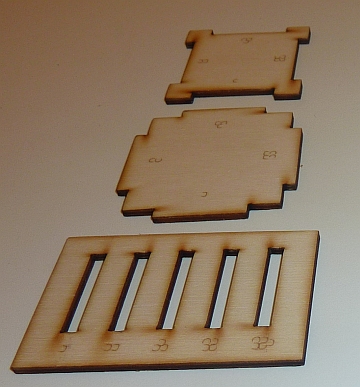
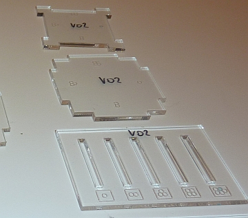
as one can see, i tested both with plywood and acrylic, and decided to go for acrylic.
cutting the actual kit!
after testing the comb and deciding what's the best combination for slot/tab sizes, i changed the 3 blocks and edited the pieces accordingly.here's a picture of the drawing ready to be exported to the laser cutter:
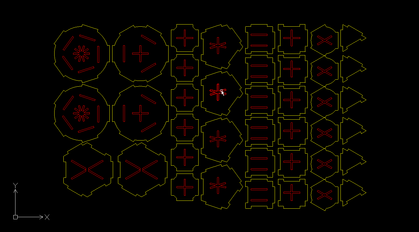
and here are the results:
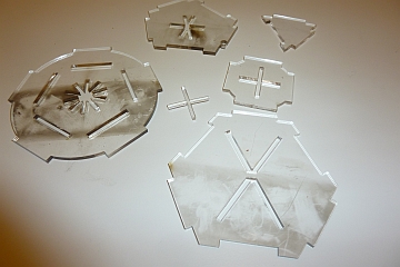
the black stains were caused by fire flames catching on on the resin leftovers of plywood boards from previous cuts.
problems...
turns out that my testing material was different than my actual working material!!! i found out the hard way that not all acrylic boards are the same.my testing board was 3 mm thick, and the board i used for the final cutting was like 0.2mm wider. that means that while the tabs can go into the side slots, they can't slide into the surface slots. that diminished quite substantially the variety of structures that could be built, but it still worked, more or less.
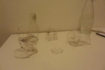
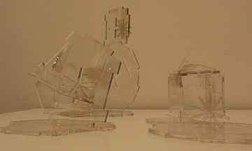
below one can see what my son managed to do before he got bored...
thats all for now.
