
Assignments

Juan Carlos Pérez Juidias. Fab Lab Escuela Técnica Superior de Arquitectura de la Universidad de Sevilla


Embedded programación (Mar 13)
Assigment Read a microcontroller data sheet. Program your board to do something, with as many different programming languages and programming environments as possible. Class syllabus:: http://academy.cba.mit.edu/classes/embedded_programming/index.html Links:: http://hlt.media.mit.edu/wiki/pmwiki.php?n=Main.AVRProgrammingAdvanced http://www.ladyada.net/learn/avr/index.html http://www.as220.org/fabacademy/tutorials/programming_FabISP.php#ubuntu http://www.as220.org/fabacademy/tutorials/hello_echo_c.php http://academy.cba.mit.edu/classes/embedded_programming/hello.ftdi.44.program.png http://www.tutorialspoint.com/cprogramming/index.htm htmaa 2012/ Travis Rich :: http://fab.cba.mit.edu/classes/863.12/people/travis.rich/week7/ Laia M-S :: http://fab.cba.mit.edu/classes/863.12/people/laia.mogassoldevila/projects/p6.html Pip Mothersill :: http://fab.cba.mit.edu/classes/863.12/people/pip/WK7/wk7.html htmaa 2011/ Mercedes Mane; assembly language :: http://academy.cba.mit.edu/2011/labs/urbana/mercedes.mane/Website/Hello_World_Serial/index_hello_world_se rial.html Shahar Ronen; avr and phython :: http://fab.cba.mit.edu/classes/4.140/people/shahar.ronen/avr_python_setup_guide.html I had a hard time with this practice. I read a lot in order to understand this practice because my programming skills are very low.
First I searched for information from colleagues who have made the practice in 2012, MIT students and my own
colleagues. I also want to thank our guru Alejandro Campos advice given to us.
Thanks to Perez de Lama, I've deciphered, a little, the world's ATTINY44A, after reading the manual and want to
understand. The types of memory and inner workings.
I also understand better the differences between different programming languages.
Once thought I had the job, I made the following steps:
ATTINY44A Read the manual to try to understand how it works. I have not been at the level that I wanted, but I
got something. (http://www.atmel.com/Images/doc8183.pdf)
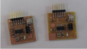
In this exercise we want light the LED pressing the button.
Find a C, study it and adapt. In this case I used Neil’s code adapted by Perez de Lama.
// Jose Perez de Lama Fab Academy 2013 17/03/13
// hello.ftdi.led.button.beta.jpl.c
// customization and comments on:
// Travis Rich 10/22/12
// an iteration on top of the following attribution:
//
// hello.arduino.168.blink.c
//
// test blinking LED
//
// Neil Gershenfeld
// 3/14/11
//
// (c) Massachusetts Institute of Technology 2011
// Permission granted for experimental and personal use;
// license for commercial sale available from MIT.
//
#include <avr/io.h>
// avr input output preprocessor library
#include <util/delay.h>
// time management preprocessor library
// Following with #define preprocessor macros probably associated to the avr/io.h library
// i have tried to find the source code for avr/io but eventually this task had to remain in the todo list
// plus macros associated to the util/delay.h library
// The following macros use bitwise operatiors to activate, disactivate or test the DDRxn, PORTxn and PINxn
registers
// PORTx, Data Direction Register DDRx, and the Port Input Pins PINx; Atmel data sheet p 53
// It would be necessary to better understand what each of these macros exactly does
#define output(directions,pin) (directions |= pin) // set port direction for output
#define input(directions,pin) (directions &= (~pin)) // set port direction for input
#define set(port,pin) (port |= pin) // set port pin
#define clear(port,pin) (port &= (~pin)) // clear port pin
#define pin_test(pins,pin) (pins & pin) // test for port pin
#define bit_test(byte,bit) (byte & (1 << bit)) // test for bit set
#define led_delay() _delay_ms(5000) // LED delay i extended it to 5000 before it was 1000
// setting the port registers DDRxn PORTxn PINxn
// led output
#define led_port PORTA
#define led_direction DDRA
#define led_pin (1 << PA7)
//button input
#define input_port PORTA
#define input_direction DDRA
#define input_pin (1 << PB3)
#define input_pins PINA
int main(void)
{
//
// main
// set clock divider to /1
// CLKPR Clock Prescale Register Atmel data sheet pp 30 32 103
//
CLKPR = (1 << CLKPCE);
CLKPR = (0 << CLKPS3) | (0 << CLKPS2) | (0 << CLKPS1) | (0 << CLKPS0);
//
// initialize LED and button pins as output and input
//
clear(led_port, led_pin);
output(led_direction, led_pin);
//
// In addition, the Pull-up Disable – PUD bit in MCUCR disables the
// pull-up function for all pins in all ports when set. Resistor associated to every pin
// Atmel data sheet p 53
// i am not sure if this is what the clear macro performs as it was commented on the file
//
clear(input_port, input_pin); // TR turn on pull-down
input(input_direction, input_pin);
//
// section of code that was outcommented by TR
// main loop
//
// while (1) {
// set(led_port, led_pin);
// led_delay();
// clear(led_port, led_pin);
// led_delay();
// }
// }
//
while (1)
{
// i dont understand the (1) parameter it seems to be a permanent pre-given condition
// TR wait for button down
//
if (0 != pin_test(input_pins,input_pin))
{
clear(led_port, led_pin);
led_delay();
// this seems to turn the led on, that is give PORTA7 the logic value of 1 / HIGH
// it seems to be triggered by pin_test = 1 which should mean the button is pressed
// maybe it is through removing the internal resistor at PINA7
// but maybe this is wrong and it works the other way around and no pull resistor is involved
// clear meaning then that the logic value is set to 0, and set, that it is set to 1
// and then the if loop would work the other way around
// this would be like in the arduino sketch the i reproduced above in this page
}
set(led_port, led_pin);
// this then might return to pull up the resistor this condition seems to happen when pin_test = 0
// or rather, after the second hypothesis it would turn the led pin HIGH
}
}
To load the module I used AVRisp2. So I installed the AVRDUDE+GCC code that would, working in Ubuntu
12.04.
Open Terminal and type:
sudo apt-get install flex bison byacc libusb-dev gcc avrdude
Then type:
sudo apt-get install gcc-avr
Type "and" when asked to do so by your system
Then type:
sudo apt-get install avr-libc
Then type (may already be installed):
sudo apt-get install libc6-dev
Compilation
Using Neil’s file I compiled the C file
make-f hello.ftdi.44.echo.c.make
Then I configured the external clock of the microprocessor, with Neil’s code.
sudo make -f hello.ftdi.44.echo.c.make program-avrisp2-fuses
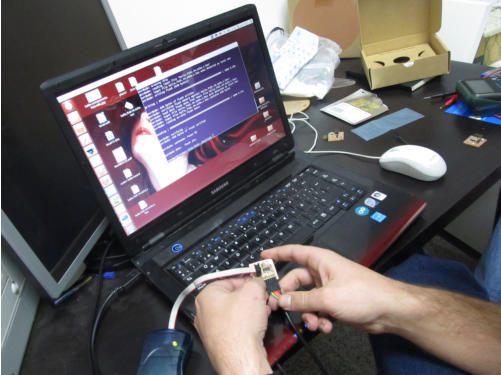
This I do after connecting the device to the computer.
Once connected to the USB port and test is right with the command in the Terminal:
lsusb
Once you have connected the cable to the board and USB to connect the AVR2 spent the board in the correct
orientation also. Once you are connected, USB connected to the computer and found that the two lights are
green AVR2.
I read a lot in order to understand this practice because my programming skills are very low.
First I searched for information from colleagues who have made the practice in 2012, MIT students and my own
colleagues. I also want to thank our guru Alejandro Campos advice given to us.
Thanks to Perez de Lama, I've deciphered, a little, the world's ATTINY44A, after reading the manual and want to
understand. The types of memory and inner workings.
I also understand better the differences between different programming languages.
Once thought I had the job, I made the following steps:
ATTINY44A Read the manual to try to understand how it works. I have not been at the level that I wanted, but I
got something. (http://www.atmel.com/Images/doc8183.pdf)
In this exercise we want light the LED pressing the button.
Find a C, study it and adapt. In this case I used Neil’s code adapted by Perez de Lama.
// Jose Perez de Lama Fab Academy 2013 17/03/13
// hello.ftdi.led.button.beta.jpl.c
// customization and comments on:
// Travis Rich 10/22/12
// an iteration on top of the following attribution:
//
// hello.arduino.168.blink.c
//
// test blinking LED
//
// Neil Gershenfeld
// 3/14/11
//
// (c) Massachusetts Institute of Technology 2011
// Permission granted for experimental and personal use;
// license for commercial sale available from MIT.
//
#include <avr/io.h>
// avr input output preprocessor library
#include <util/delay.h>
// time management preprocessor library
// Following with #define preprocessor macros probably associated to the avr/io.h library
// i have tried to find the source code for avr/io but eventually this task had to remain in the todo list
// plus macros associated to the util/delay.h library
// The following macros use bitwise operatiors to activate, disactivate or test the DDRxn, PORTxn and PINxn
registers
// PORTx, Data Direction Register DDRx, and the Port Input Pins PINx; Atmel data sheet p 53
// It would be necessary to better understand what each of these macros exactly does
#define output(directions,pin) (directions |= pin) // set port direction for output
#define input(directions,pin) (directions &= (~pin)) // set port direction for input
#define set(port,pin) (port |= pin) // set port pin
#define clear(port,pin) (port &= (~pin)) // clear port pin
#define pin_test(pins,pin) (pins & pin) // test for port pin
#define bit_test(byte,bit) (byte & (1 << bit)) // test for bit set
#define led_delay() _delay_ms(5000) // LED delay i extended it to 5000 before it was 1000
// setting the port registers DDRxn PORTxn PINxn
// led output
#define led_port PORTA
#define led_direction DDRA
#define led_pin (1 << PA7)
//button input
#define input_port PORTA
#define input_direction DDRA
#define input_pin (1 << PB3)
#define input_pins PINA
int main(void)
{
//
// main
// set clock divider to /1
// CLKPR Clock Prescale Register Atmel data sheet pp 30 32 103
//
CLKPR = (1 << CLKPCE);
CLKPR = (0 << CLKPS3) | (0 << CLKPS2) | (0 << CLKPS1) | (0 << CLKPS0);
//
// initialize LED and button pins as output and input
//
clear(led_port, led_pin);
output(led_direction, led_pin);
//
// In addition, the Pull-up Disable – PUD bit in MCUCR disables the
// pull-up function for all pins in all ports when set. Resistor associated to every pin
// Atmel data sheet p 53
// i am not sure if this is what the clear macro performs as it was commented on the file
//
clear(input_port, input_pin); // TR turn on pull-down
input(input_direction, input_pin);
//
// section of code that was outcommented by TR
// main loop
//
// while (1) {
// set(led_port, led_pin);
// led_delay();
// clear(led_port, led_pin);
// led_delay();
// }
// }
//
while (1)
{
// i dont understand the (1) parameter it seems to be a permanent pre-given condition
// TR wait for button down
//
if (0 != pin_test(input_pins,input_pin))
{
clear(led_port, led_pin);
led_delay();
// this seems to turn the led on, that is give PORTA7 the logic value of 1 / HIGH
// it seems to be triggered by pin_test = 1 which should mean the button is pressed
// maybe it is through removing the internal resistor at PINA7
// but maybe this is wrong and it works the other way around and no pull resistor is involved
// clear meaning then that the logic value is set to 0, and set, that it is set to 1
// and then the if loop would work the other way around
// this would be like in the arduino sketch the i reproduced above in this page
}
set(led_port, led_pin);
// this then might return to pull up the resistor this condition seems to happen when pin_test = 0
// or rather, after the second hypothesis it would turn the led pin HIGH
}
}
To load the module I used AVRisp2. So I installed the AVRDUDE+GCC code that would, working in Ubuntu
12.04.
Open Terminal and type:
sudo apt-get install flex bison byacc libusb-dev gcc avrdude
Then type:
sudo apt-get install gcc-avr
Type "and" when asked to do so by your system
Then type:
sudo apt-get install avr-libc
Then type (may already be installed):
sudo apt-get install libc6-dev
Compilation
Using Neil’s file I compiled the C file
make-f hello.ftdi.44.echo.c.make
Then I configured the external clock of the microprocessor, with Neil’s code.
sudo make -f hello.ftdi.44.echo.c.make program-avrisp2-fuses
This I do after connecting the device to the computer.
Once connected to the USB port and test is right with the command in the Terminal:
lsusb
Once you have connected the cable to the board and USB to connect the AVR2 spent the board in the correct
orientation also. Once you are connected, USB connected to the computer and found that the two lights are
green AVR2.
 Finally, I downloaded the program in the ATtiny44
sudo make -f hello.ftdi.44.echo.c.make program-avrisp2
So, connect the cable to the board FTDI designed in Electronic Design Week.
The cable must be connected in the correct orientation and connect the other way would kill the microprocessor.
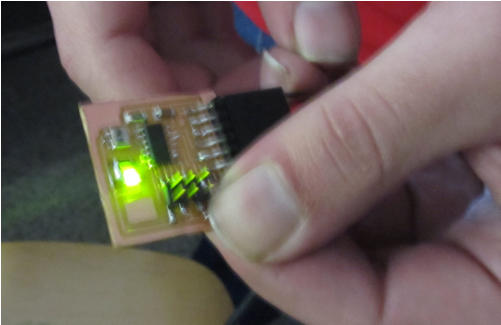
Once loaded the code on our board AVR2 programmer unplugged and found that it works with a satisfactory
result.
DONE, THANK YOU
Finally, I downloaded the program in the ATtiny44
sudo make -f hello.ftdi.44.echo.c.make program-avrisp2
So, connect the cable to the board FTDI designed in Electronic Design Week.
The cable must be connected in the correct orientation and connect the other way would kill the microprocessor.
Once loaded the code on our board AVR2 programmer unplugged and found that it works with a satisfactory
result.
DONE, THANK YOU