mechanical design, machine design
Week 15 Overview
The assignment for this weeks Mechanical design is to as a group :
- make a machine, including the end effector
- build the passive parts and operate it manually
- document the group project and your individual contribution
The assignment for this weeks Machine design is to as a group :
- automate your machine
- document the group project and your individual contribution
For the project Fab Academy sent us out a pack for building the machine and we have build it and program it to do whatever
we would like it to do.We decided to create a drawing robot.
- Link to MITs Machines that Make website
- Link to the Gestalt and Modular Machine that Make
- Link to MITs Machines that Make:cardboard stages website
Planning
First of all we worked out a plan of what to build and how to build it. Insert drawings of what we're going to make. We decided to create a drawing robot with bar set horizontally with one of the motors on it and a pen. This horizontal bar is mounted on carriages at either end of the horizontal bar. The vertical bars on either side also have motors on them to move the horizontal bar up and down. Controlling these means we can create drawing robot. Our laser is out of action at the moment so we worked out how we could build the physical components without the laser. Graham and myself worked out some modular pieces that we could use to 1) hold the bars in place, 2) hold the motors, 3) create a carriage that bars can slide through all of these pieces are pretty much modular with one or 2 alterations. Making the machine without using a laser also means that any labs or people that have access to 3D printers but not laser cutting can still make these. So we've altered the physical parts of the design. The other pieces we need were: 4) a base to mount all of the components on 5) a pen holder
1) Making holders for the rod, motors and drawing page.
Between Graham and I, we mainly worked on this part of the project. Graham made some of the pieces by hand (well wood working) and I made some of the
components using the 3D printers. I think the end result is quite nice because you could see
the pros and cons of digital manufacturing the pieces or making them by hand. By hand it
was a much quicker process as the larger 3D prints took 3 hours but the accuracy
wasn't 100%.

We also needed some more of the holders for the rods so I made a new 3D model for this and
printed a few extra of these. You can see them shown in the photo on the right.
Download the files for the laser and 3D prints below:
- Download the files for the 3D printed carriages we made, here
- Download the files for the laser cut carriages we made, here
- Download the files for the rod sleeves we made, here
2) Pen Holder
The next thing to do was to make a holder for the pen. We used a mixture of 3D printing
and laser cut pieces with some extra pieces like springs and elastic bands.
After a few iterations to get this right. It took a bit of work to consider different pens sides,
lengths, diameters and the downward pressure that should be apply. You can see all the various
models we made in the images below.

- Download the files for the pen holder we made, here
3) Other parts of the project
Iain worked on the getting the stepper motors working and communicating
with the driver boards. Here's a link to Iain page where the is more documentation for the motors and
driver boards.
Jialin worked on the software that takes in a jpeg image and create a kind of dot
image shown on the right.
Here's a link to Jianlin's page where the is more documentation
about the software.
4)Assembly and the final machine
We all worked together on assembling the machine which worked quiet well.
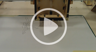
Here's a video of the drawing robot in action.
Download Files
Week 15, May 1
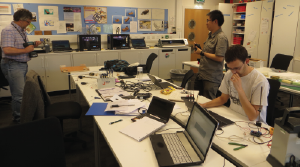
Us working in the lab on the machine and mechanical design project
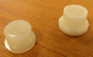
3d printed rod holder sleeve and the original one too
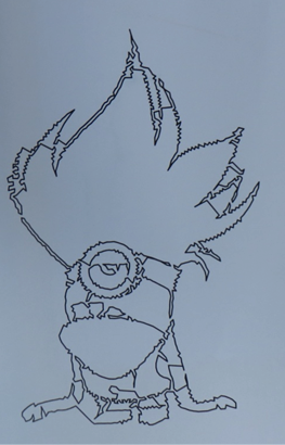
The output of the drawing machine .
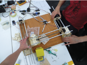
Assembly the drawing machine .