WEEK 6
[ELECTRONICS DESIGN]
Continuing my learning process in electronics, this week I made changes to a echo_hello-world board by adding a led and a switch. For the board design I chose Eagle_CAD. A free software specific for pcb design, routing and fabrication.
So, first off, I downloaded Eagle CAD and the FabAcademy libraries.
Those libraries contain the main components you'll need during the FabAcademy course.
Open the zip file and unzip all the .lbr files to
"your eagles directory"\lbr. Before you run Eagle It's probably a good idea to watch the following three tutorials from Jeremy Blum. You'll quickly learn the basics.
By the way, this is the list of components from Digikey for the hello-world board with the SMD led and switch. Enjoy!
http://www.digikey.com/product-detail/en/ECS-CR2-20.00-B-TR/XC1109TR-ND/813196
http://www.digikey.com/product-detail/en/RC1206FR-0710KL/311-10.0KFRCT-ND/731430
http://www.digikey.com/product-detail/en/RC1206FR-07499RL/311-499FRCT-ND/731891
http://www.digikey.com/product-detail/en/C3216X7R1H105K160AB/445-1423-1-ND/569089
http://www.digikey.com/product-detail/en/ATTINY44A-SSU/ATTINY44A-SSU-ND/1914708
http://www.digikey.com/scripts/DkSearch/dksus.dll?WT.z_header=search_go&lang=en&keywords=S1143E-36-ND&x=-1137&y=-51&cur=USD
http://www.digikey.com/product-detail/en/95278-101A06LF/609-3487-1-ND/2044025
http://www.digikey.com/product-detail/en/B3SN-3112P/SW262CT-ND/60835
http://www.digikey.com/product-detail/en/LTST-C150CKT/160-1167-1-ND/269239
After starting Eagle I clicked the add button and picked all the components needed. These are the Fab Academy libraries:
- 01_fab
- 01_FAB_Hello
- 01_ng
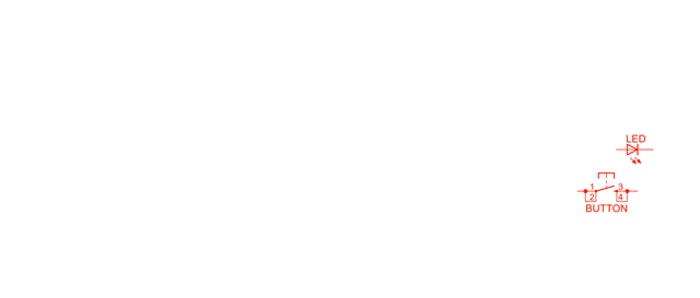
I connected the chosen components with wire and labeled the disconnected ones so that the schematic looks cleaner. See the image below. After that the first step of designing electronics was sucessfully completed.
Before we continue, there are some important tips for knowing what you're doing:
Attiny - is the micro-controller that will storage and process your instructions;
20Mhz resonator - will be used as an external clock for the Attiny, speeding up the processor clock and guaranteeing more accurate results;
FTDI header - powers the board and allows communication with the computer;
6 pin programming header -for communicating with the ISP programmer made on week 4;
capacitor - is used here between the VCC and the GND to stabilize the current, avoiding any small spikes on the system.

Now that you know you're not making a bomb, It's time to choose the components location on the board and draw the routes between them. So I clicked
Generate/switch to board and Eagle opened another window, this time with the pads drawn and lots of yellow wires. Those wires helped me to route my board manually, but you can instead automatically route it with the autorouter button on the left, although for complex designs I don't recommend it. In this case I optimized my routes so that the led and the button could be apart from the rest of the components, for being easy to reach.
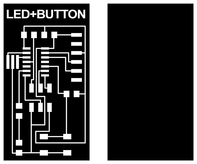
After I finished designing my board, I exported it as an image for later post-process with Fabmodules. When exporting, It's crucial to use at least 1000 DPIs of resolution, so that Fabmodules can generate a correct G-Code with straight lines.
Now that you got your design ready it's time to repeat the process learned during the week 4.
Special note about the image above, the scale is not correct. You really need to design your board!

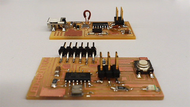
After milling your board and soldering the components, this should be your final result. An ISP fabricated on week 4 and a led+button board. On week 8 we will program this board so that it blinks when you press the button.


