Not much to add. We got together met all the local classmates and got a lecture about the way the classes were going to take shape
Step 1: Followed this tuturial on mercurial and had a few problems. Since i'm new to ubuntu (and linux in general) i'm not very fluent inside the terminal.
Step 2: we had to create a student website to document our final project and our classes. I've created numerous site in the past but it's been a while since i made a site in purely html (using mostly blog sites, dreamweaver and various CMS's) so i decided to follow a tutorial to brush up. This is the tutorial i used to create this site. This tutorial is a great start for anyone not familiar with html and css. Another great resource on html, css or anything web based is http://www.w3schools.com/
This week we'll be making a 2d/3d model of our final project and hopefully animating this model. I have some experience in 2d cad (eagle and frontpanel designer) and vector (illustrator and inkscape). Then again my knowledge of 3d modelling is ZERO... I've tried a little SketchUp in the past weeks but i hated the fact that i didn't have easy acces to numerical input. Rhino3d was better in that respect, but i was lost in all the options. So i guess i'll be exploring different tools in the coming week and doing a lot of tutorials.
(update 8 February 2011) So it's been a week to try out all the different programs and create something. Like i said my experience with 3d modelling is ZERO. So here's my lowdown on all the programs i've tried.
This week we've been doing some laser cutting. Not hard at all! If you can print a file to a printer you can laser cut/engrave.
To be honest i didn't really read up on the machine before i went to cut. But i was lucky that i was able to observe some other people trying it out and some of the nice people at the fablab helped me to get started. Next time i'm using one of the other machines, i'll read the manual BEFORE i start. Looking for the manual after i used the machine on the laser pro website turned up NOTHING! But luckily google is your friend. here's a direct link to a manual LINK.
I also found a link to a tutorial made by the IAAC Fablab in Barcelona. However i found some glaring errors in the document. you can find this document HERE.
Here follow some tips i found out using the machine.
So here is a picture of my end result.
I didn't really had anything in particular that i want to make a press-fit-kit of, so i just made some generic building-blocks to construct shapes out of. The vector file i used for cutting my shapes will come here. (need to find some kind of hosting for this big file)
These are the settings i used to cut the cardboard: speed:12, power:100%, PPI:400. ( i have the feeling that the laser cutter's lens and mirrors were either dirty or damaged, because the settings i needed to use to cut my material was almost the same as the settings for cutting wood or plexiglass.)This week we've been building the FabISP a simple low cost In System Programmer. To make it we had to mill the pcb on the modela, solder the components and then program it using another ISP.
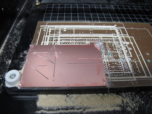
Milling the PCB: We used the fabmodules to drive the Modela. Apparently the cable connecting the Modela to the computer needs to be a specific cable otherwise the modela will freak out and mill like a monkey on crack. See the picture below from Massimo from fablab Aalto
Friso Joris Gerson here in amsterdam is currently maintaining a wiki on the modela with more info on the issue here.
The procedure to mill on the modela is really confusing at first, but like every thing, once you understand it (and everything is working), it's easy. First you start up the fab modules and import the .png (500DPI) you want to engrave. I made the FabISPKey. Now you set the settings used to make the path used by the bit to mill the board.
here are the settings i used for engraving:
Next you use "make .path" to apply your settings and then you can use "view .path" to view the path generated in okular. This is handy since it allows you to view the paths in greater detail.
After this you will need to set the home point using the Xmin and Ymin settings underneath the "make .rml" button. If you are using a fresh pcb and have it stuck to the milling bed in the lower left corner you can just leave it to the default settings. By using the "move to xmin,ymin" button you can move the bit to a designated coordinate. You can use this to check your start point settings or for nulling the drill-bit to your surface (i used an offset point in the middle of the board to null the bit to my surface just to compensate for any burrs at the edge). If you are using a pcb which has already some parts milled out you can set the start point here too. Just measure with a caliper and set an offset start point. This setting will be applied when you press "make .rml". i left the Speed and Jog settings to their defaults of 4 and 1 respectivly.
To insert the tool you will need to press the "up" and "down" buttons on the modela at the same time. The Modela will move the tool holder to it's resting position. Now you can insert the tool you want to use. Just use one grub screw to tighten the tool and insert the tool as high as practical. Next use the "move to Xmin,Ymin" button to move the drill above the board you want to mill. While holding the drill untighten the drill and slowly drop it on the pcb you want to mill. Now while still holding the drill Tighten the drill in the holder. This calibrates the z axis.
now you reset your Xmin and Ymin settings to your start point if you used a different setting for setting the z axis. Next you make the .rml file using the aptly named "make .rml" button. triple check the drill and you settings and then press the big "send it!" button to make the modela do your bidding. Now laugh like an evil scientist or just get a coffee while the modela will mill your board.
To cut out your board and/or mill any holes you repeat the above steps but change a few settings. Do make sure that the xmin and ymin settings are the same as befor. Here are the settings i used for cutting my board:
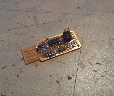
Hopefully your board is now nicely milled. So we can go on to the Soldering. I have a lot of experience in soldering, but only with thru-hole boards.... I know i need glasses so a lot of cursing went on... However at the end it was nice to finish it and add smd hand soldering to my repetoire. I love the idea to miniaturize boards and the idea of getting a cheap infrared oven to make a reflow oven. But those are future projects. Back to the isp. Btw the eagle files and more documentation for the fabispkey can be found on git via this command:
git clone git://bardagjy.com/fabisp i believe the firmware is included too.
next up is flashing your board. To do this follow these steps:
Now if all went well, unsolder SJ1 and SJ2. Then check your isp by programming something with it. Using the same commands as above only with the relevant firmware for the board you want to program. On some OS's you might need to install the usbtiny driver first for it to work.
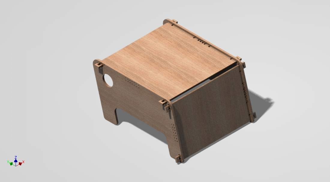
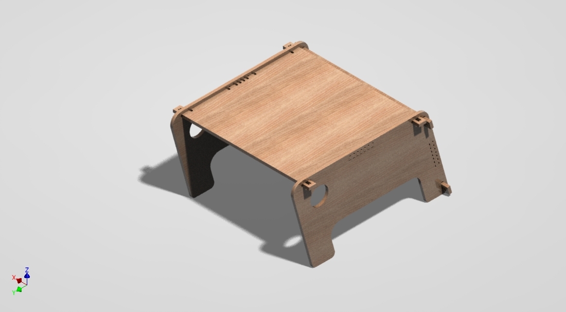
for this weeks assignment we all got one plate of wood (244cm x 122cm x 1.5cm( i chose multiplex) ) and we had to use that to "make something big" on the cnc router. Alex was also kind enough to provide us with a link to a collection of wood-joints developed specificly for cnc routing. For my design i had the idea to make a coffee-table which could be flipped to make a small desk. This is the preliminary design i did in AutoDesk Inventor.
One of the problems i encountered during the use of the shopbot was that the partsworks software could not open my .dxf files. Apparently Partsworks can only import .dxf files which conform to the "2000" standard and not the "2011" standard used by Autodesk Inventor. Inventor does not have any options for changing the "format" of dxf file it generates. So to remedy this problem i had to import the files to CorelDraw and export it there to a different dxf format. Sometimes however coreldraw would not import them correctly so i had one rogue vector that would curl across my file..... very frustrating. To remedy this i had to import it in solidworks and use that to export it to a different dxf format. I find it very strange that the company (autodesk) that invented the dxf file format does not offer an export option where you can keep your dxf file backwards compatible with other software. Autodesk i love your software but i have to give you one downvote.....
The other problem i encountered was when i was routing my test joints. All the cuts would be off by a 2/10th of a millimeter. At first i thought it might have been caused by some freak conversion problem in either solidworks or coreldraw. But measuring my vectors in partsworks showed me that the files were spot on. The other thing i checked was if the bit i was using was smaller than i said on the side of the bit. This was not the case so that ruled out that possibility. Not wanting to re-design my files, i found a different way to correct for this offset. I told the partsworks software that my bit was smaller than it in reality was when making my toolpaths. Thus correcting for the offset cuts. after a few trail and error jobs i found a setting that worked perfectly. Since i did not have any time left i saved my settings and called it a day. Next time i had some time on the machine i decided to cut my whole piece, but not before i tried one more test to check if the settings were still ok (better save than sorry). During this test i had the same problem as before! Not as bad but the problem was still there. Since i made this test on the other side of the bed as when i did my first tests i decided to test it again on the same spot as i did before. This test worked flawlessly again with the same settings as before. Therefore i think i can concluded that our shopbot might need some calibration/squaring.
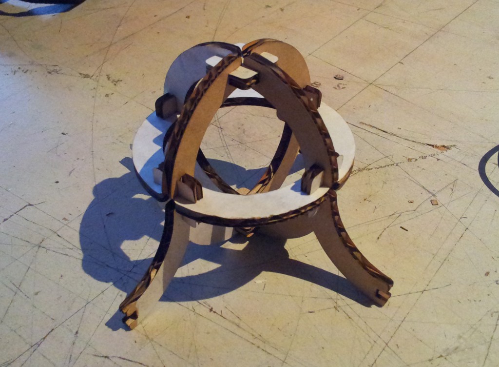
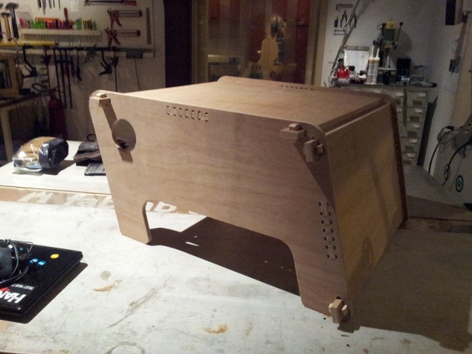
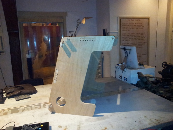
After getting everything to fit after some more tests i had the shopbot route out all the parts i needed. And i was really happy to see that everything fit perfectly. Here's how my my project turned out in real life:
And here is a short video i made:
The assignment for this week was: take the ftdi.hello.world board and add at least a button and a led. The other part of the assignment was getting settled on a software package to draw and route Printed Circuit Boards. Since i've been using Eagle for a at least 5 years now this last part was a no brainer.
To give me somewhat of a challenge i decided to add a button for reset, a button for user input, a LED and a freescale accelerometer. I've never used a accelerometer, so i liked the idea of using it to make a nightlight for children that will start if you shake it and will fade out slowly over the course of about half an hour.
Here are the files i created. (Updated. See embedded programming)

And now on to what i did wrong. First thing was that i did not do a Design Rule Check. So when i tried to look at the toolpaths in the fabmodules i could see parts not milled. Easily solved by changing my layout in eagle. Next thing was i made a library for the Freescale MMA1260eg, but i i thought it was a soic 14..... i turned out to be a soic16 (only just a little wider) so i had to rewrite the library. Third problem i encountered was that i made my traces 12mill wide but 1 trace almost came off since it was so thin. Easily solved with a wire bridge, but it should not have been neccesary if i made my traces a little wider. And the last my second board did not get cut out... i set the depth to -1.5 (board was 1.45) but it only milled to about 0.5 depth. For this last problem i have no idea why... i found out when i took the board off so i just used a bandsaw to correct it. The Milling-bit looks to be intact so that can't be it either. Further investigation will need to be done, but for now i'm happy.
For the my assignment i used a chess piece as my the base of my mold. I cut the piece in half in Inventor and added notches and holes around the design. I also added chamfers and fillets to those hole and notches to help with releasing the mold when the material was cast. I also chamfered the outline for the same reason. You can see the designs for the wax molds below.
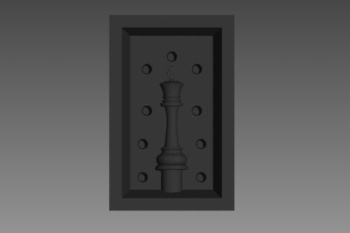
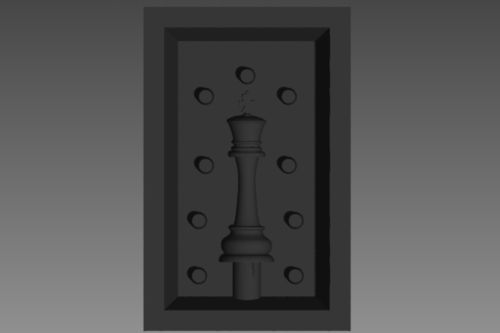
The wax molds were not perfectly milled. On one of my wax molds an error in the toolpath created small platforms when it encountered a hole. As you can see below.
these are the settings i've used for the roughing cut
End mill 0.125 inch - RPM of 3500 - Feedrate of 60 - Plungerate 10 - Stepover 0.635mm
and these are the settings i've used for the finishing cut
Ball nose mill 0.0625 inch - RPM of 3500 - Feedrate of 40 - Plungerate 10 - Stepover 0.0031mm
To calculate the volume of my molds i used the material properties in inventor. First i wrote down the volume of the design as is. Then i filled in the mold cavity and wrote down the resulting volume. then it was simply a question of deduction both values and the result is the volume of your mold. Then you simply fill in your mold volume in the calculator on the smooth on site. Link found here
The material i used for the flexible molds was -smooth-on 121/30 dry-. The ratio of a and b was 50/50 so very easy to measure out. I placed the filled wax molds in the oven on the lowest setting for an hour and then demolded them. Below you can see my resulting molds.
Next up is filling my molds.....
During my first try to filling the molds i used smooth cast 300. This was a complete mistake. The material hardened so quickly that before i knew it, it went from completely liquid to solid within seconds ruining my mold in the process. I didn't pour the material quickly enough since i still had Neil's advice in the back of my head; "if you think you've mixed it good enough, mix it some more...". I had used plenty of mold release, but as you can see the material did not have a chance to form a single solid object so it was impossible to save my mold. So if the box says pot life of 3min that truly means just 3minutes ;)
(alas my phone got stolen so i have no more pictures of my ruined mold)
For my second try i made new poly urethane molds (this time no more air bubbles yay!). And for the casting material i have used smooth-on EpoxAcast 690 clear epoxy resin. This material has a curing time of 5 hours so this time i had plenty of time to pour the mold. This material has a mixing ratio of 100:30 for material A and B respectivly. I sprayed plenty of mold release (at least more than last time, just to be sure) and left the mold to rest for 5 minutes. Just enough time to measure and mix the Epoxy. I mixed a little bit more than needed since i read that the material shrinks during curing. I did notice that the material shrunk during the curing, but since my molds have a relatively big inlet (in relation to the size of the model). I could have just ignored the shrinkage. For bigger molds having extra material to spare is advisable. For the curing i just left the filled mold at room temperature over night. Below is how my second try turned out.
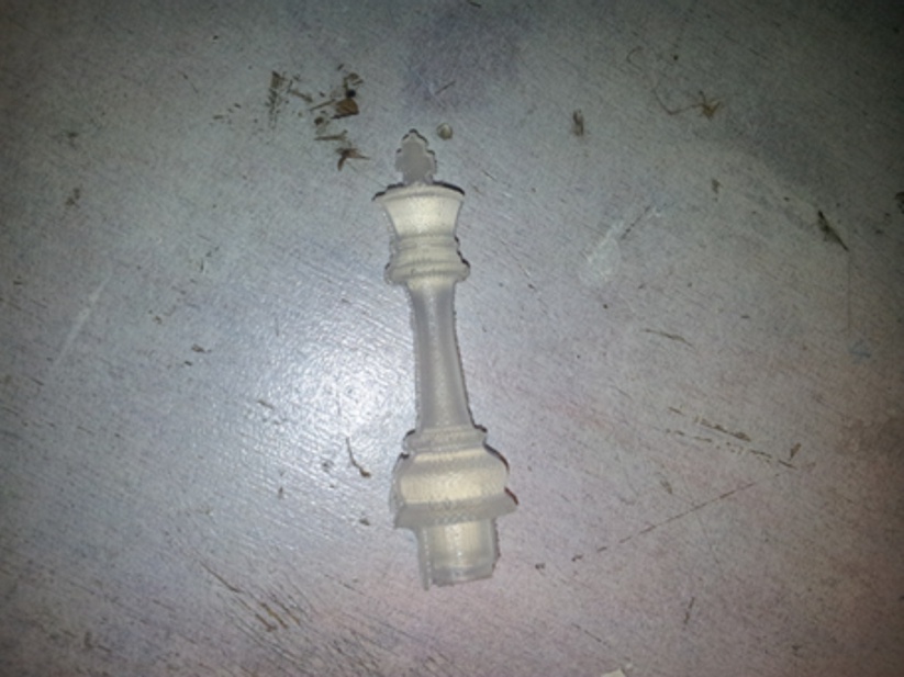
As you can see the cast turned out pretty neat. It still needs some post-processing like sanding and cutting of the inlet. All in all i'm pretty happy with the end result and i would love to try some more casting materials to get some more experience
...
This week we've been busy programming the boards we've made for the electronics production class. In the beginning my week started great. Uploaded the hello.ftdi.44.echo.c code and everything was working perfectly. Since i've only ever worked with the arduino ide, i decided to start with the hi-lo tech arduino adaptation for the attiny. I did this just to check if everything was working with my board.
At first everything seemed just perfect. The button worked, i got the led blinking and fading. Then i decided to try out if the accelerometer worked. And at first i only got a straight 0 Value (0V input) on the ADC. Hmmm not ok, so i started checking the connections to the Freescale MMA1260EG. All the connections seemed fine, no shorts and good solder connections. Then i checked the power pin and i got no 5V. I checked the trace going up to the chip and that had a nice solid 5V on it. I concluded that the trace must be faulty going from my bypass cap to the chip. Happily i soldered a jumper wire from the working 5V to the power pin. Connected the programmer back up and the ftdi cable (green light came on on the avrispII) and watched in the serial monitor to see if the value was correct. Suddenly my laptop started revving it's fan and it started the boot down sequence. After that i started smelling the typical smell of burning silicon... hmmmm, not good. The broken trace should have been an early warning, because a quick gander at the datasheet of the MMA1260EG showed that i had swapped the VSS and the VDD pin for the MMA1260EG. A pretty embarassing mistake for the person that is supposed to maintain the eagle libraries for the FabAcademy.....(never make a eagle Library late at night) What had happened is that the trace had burned up at the thinnest spot (under the chip) and thus was not interfering any more with the rest of the circuit (so all seemed well). When i added the jumper wire i made an ever bigger pipe for the 5V supply to reach the chip and thus burned the chip and the rest of the circuit.
Needless to say i updated the eagle library and since i was already updating my pcb, i added an extra button. The Electronics design portion of classes page has been updated accordingly. A day later i milled the board and soldered the components. Finally back to the programming. Like the first board i tested everything with the arduino ide. This time round all was well and i even got readings from the accelerometer. Succes!
Here are is a graph i made using processing whilst i was capturing the data from the attiny. I was flipping the board and shaking the board as you can see on the graph.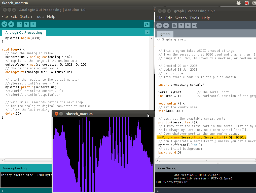
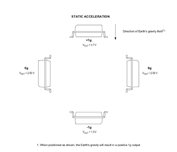
This excerpt from the mma1260ef datasheet shows how output voltage relates to the orientation of the chip.
Below you will find the arduino code i used to make the graph
#include <SoftwareSerial.h>

/*
 Analog input, serial output

 Reads analog input pin 7, then prints the results to the serial monitor.

 uses SoftwareSerial because the arduino ide does not support hardware serial
 on the Attiny44a

 by Thomas Hopman

 This example code is in the public domain.

 */
SoftwareSerial mySerial(0, 1);


// These constants won't change.  They're used to give names
// to the pins used:
const int analogInPin = A7;  // Analog input pin that you are reading


int sensorValue = 0;        // value read from the analog input


void setup() {
  // initialize serial communications at 9600 bps:
  mySerial.begin(9600);
}

void loop() {
  // read the analog in value:
  sensorValue = analogRead(analogInPin);


  // print the results to the serial monitor:
  mySerial.println(sensorValue);

  // wait 10 milliseconds before the next loop
  // for the analog-to-digital converter to settle
  // after the last reading:
  delay(10);
}
And this is the code i used on the processing side
// Graphing sketch


 // This program takes ASCII-encoded strings
 // from the serial port at 9600 baud and graphs them. It expects values in the
 // range 0 to 1023, followed by a newline, or newline and carriage return

 // Created 20 Apr 2005
 // Updated 18 Jan 2008
 // by Tom Igoe
 // This example code is in the public domain.

 import processing.serial.*;

 Serial myPort;        // The serial port
 int xPos = 1;         // horizontal position of the graph

 void setup () {
 // set the window size:
 size(400, 300);

 // List all the available serial ports
 println(Serial.list());
 // I know that the first port in the serial list on my mac
 // is always my  Arduino, so I open Serial.list()[0].
 // Open whatever port is the one you're using.
 myPort = new Serial(this, Serial.list()[0], 9600);
 // don't generate a serialEvent() unless you get a newline character:
 myPort.bufferUntil('\n');
 // set inital background:
 background(0);
 }
 void draw () {
 // everything happens in the serialEvent()
 }

 void serialEvent (Serial myPort) {
 // get the ASCII string:
 String inString = myPort.readStringUntil('\n');

 if (inString != null) {
 // trim off any whitespace:
 inString = trim(inString);
 // convert to an int and map to the screen height:
 float inByte = float(inString);
 inByte = map(inByte, 0, 1023, 0, height);

 // draw the line:
 stroke(127,34,255);
 line(xPos, height, xPos, height - inByte);

 // at the edge of the screen, go back to the beginning:
 if (xPos >= width) {
 xPos = 0;
 background(0);
 }
 else {
 // increment the horizontal position:
 xPos++;
 }
 }
 }
Let's take a step back. For all this to work i'm using the Arduino
ide. But wait a minute.... the attiny84/44/22 cores are not supported
by the arduino ide. The solution is a set of hardware rules that enable
the Arduino ide to program a attiny. Which is nice, since all the
supported uC's are rather big and the attiny is a lot cheaper, perfect
for simple tasks. Those rules can be found here. Alternatively you
can find a different
solution here + a
nice list of all available solutions.
i've made a piece of code that replicates the function of the hello.ftdi.44.echo.c code provided by Neil using the arduino ide. The code is as follows:
#include <SoftwareSerial.h> // include SoftwareSerial since normal serial out is not supported

SoftwareSerial mySerial(0, 1);// set the ports the ftdi cable uses for Rx and Tx

void setup()
{
  // set the data rate for the SoftwareSerial port; 4800 - 57600; 115200 does not work!
  mySerial.begin(57600);

}

void loop() // run over and over
{
  if (mySerial.available()){
    mySerial.print("hello_attiny_44_ftdi_echo:    ");
    mySerial.write(mySerial.read());
    mySerial.println();
  }

}
One of the disadvantages of using the arduino ide on a attiny is that you're effectivly adding another layer between your code and the processor on a attiny. Thus making your code bigger and slower.
One of the advantages is that the code is a lot simpler for a novice to code. For me this was a way of doing things on a attiny that i can already do on a "arduino".
The other development enviroment i have tried is AVR Studio 5. I had some driver problems with win avr and arduino with the avrispv2. After installing Avr Studio. Since AVR Studio uses it's own jungo driver which interferes with the standard driver used by winavr and arduino. To solve this you install a filter for Libusb32 which is a generic usb driver used by both drivers. The filter will redirect the winavr driver to the new jungo driver and keeps all software happily existing along each other. You can find the libusb32 files here .
Programming in AVR studio 5 is much more direct than witin the arduino ide. All my familiar functions and commands do not work and i felt a little bit daunted by programming the uC this way.... A few tutorials later i had this code up and running on my attiny to blink my led. All it does is set all the port B pins to outputs and toggles their state.
/*
 * FabBoard.c
 *
 * Created: 20-3-2012 21:35:41
 *  Author: Thomas Hopman
 */

#define F_CPU 20000000UL
#include <avr/io.h>
#include <util/delay.h>
int main(void)
{
	DDRB=0xFF;                   // Set all the PORTB bit (8 bit) for Output
    while(1)
    {
      PORTB=0xFF;                // Turn On all the PORT B bit
      _delay_ms(500);            // Delay 500 millisecond
      PORTB=0x00;                // Turn Off all the PORT B bit
      _delay_ms(500);            // Delay 500 millisecond
    }
}
First thing i noticed was that the delay of 500ms felt more like 4 seconds.
So 4 seconds on and two seconds of. If i commented out the line:
//#define F_CPU 20000000UL
then timing was better but still off way off. After consulting the datahsheet
and checking my fuses in AVR studio i found the clock prescaler fuse: CKDIV8
which divides the incoming clock by 8 to enable a attiny to run from a higher clock
at a lower power voltage. This because the CPU can not run on high speeds at a
lower power voltage. After disableling this fuse the timing was correct and the code ran
perfectly as is.
update 28-march-2012
the following code will blink the led at either 100 ms or 500 ms as set by pressing one of the 2 user input buttons
/*
 * _2buttonsBlink.c
 *
 * Created: 28-3-2012 14:20:04
 *  Author: Thomas Hopman
 */

#define F_CPU 20000000UL

#include <avr/io.h>
#include <util/delay.h>

#define SWT1 PINA2							// Define ext switch on pin PA2
#define SWT2 PINA3							// Define ext switch on pin PA3

#define LED  PORTB2							// Define ext led on pin PB2

unsigned char A;
unsigned char B;
unsigned char C = 0;
int i;

int main(void)
{
	 DDRB |= (1 << LED);		//
	 DDRA = 0b00000000;			// set all bits on data direction register A as Input


	for(;;)
	{
		A = bit_is_clear(PINA,PINA3); // Read PINA3 and store it in variable A

		B = bit_is_clear(PINA,PINA2); // Read PINA2 and store it in variable B

		if (A == 1)			// Read SWT pin (if SWT pressed, do the loop one time)
		{
			C = 1;
		}

		if (B == 1)			// Read SWT pin (if SWT pressed, do the loop one time)
		{
			C = 0;
		}

		if (C == 0)
		{
			PORTB &= ~(1 << LED); // Set 0 on LED pin (led turn off)
			_delay_ms(100);
			PORTB |= (1 << LED); // Set 1 on LED pin (led turn on)
			_delay_ms(100);
		}
		else
		{
			PORTB &= ~(1 << LED); // Set 0 on LED pin (led turn off)
			_delay_ms(500);
			PORTB |= (1 << LED); // Set 1 on LED pin (led turn on)
			_delay_ms(500);
		}

	}
}
The following code will enable Pulse Width Modulation on PORTB2
/*
 * PWM.c
 * Title: Change duty cycle PWM
 * Created: 27-3-2012 21:23:42
 *  Author: Thomas Hopman
 */

 #define F_CPU 20000000UL // Define software reference clock for delay duration
 #include <avr/io.h>
 #include <util/delay.h>
 #define LED PORTB2       // Define LED on PORT B2
 int i ;

 int main (void)
 {
 DDRB |= (1 << LED); // OC0A on PB2

 TCCR0A |= ((1 << COM0A1) | (1 << COM0A0) // COM0A1 - COM0A0 (Set OC0A on Compare Match, clear OC0A at TOP)
 | (1 << WGM01) | (1 << WGM00));		  // WGM01 - WGM00 (set fast PWM)
 OCR0A = 0;								  // initialize Output Compare Register A to 0
 TCCR0B |= (1 << CS01);					  // Start timer at Fcpu / 256

 for (;;)
 {

 for (i = 0 ; i < 255 ; i += 1 ) // For loop (Up counter 0 - 255; increment i by 1)
 {
	OCR0A = i;			// Update Output Compare Register (PWM 0 - 255)
	_delay_ms(1);		// Optional Delay
 }

 for (i = 255 ; i > 1 ; i -= 1 ) // For loop (down counter 255 - 0; decrement i by 1 )
 {
	OCR0A = i;			// Update Output Compare Register (PWM 0 - 255)
	_delay_ms(1);		// Optional Delay
 }
 }
 }
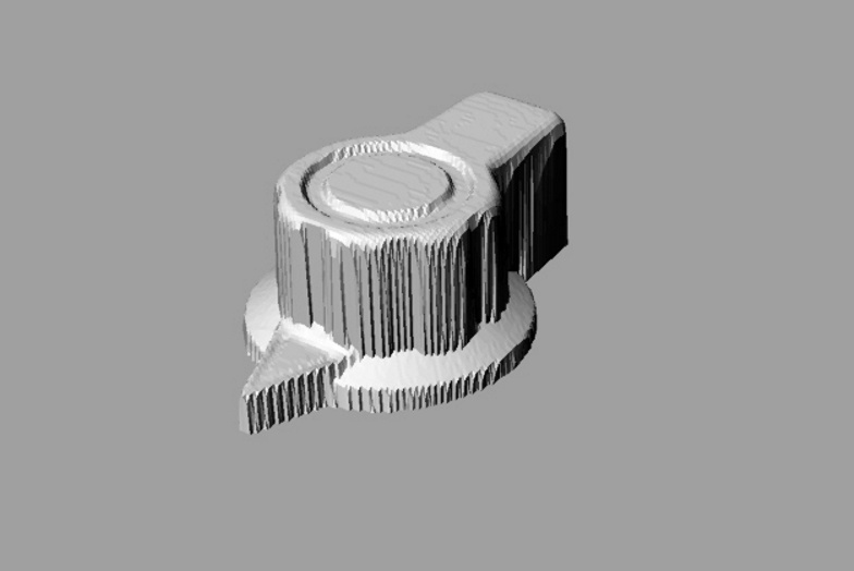
For this week i decided to scan a vintage marconi knob from an old 50ies decade box on the modela. The scanning itself was quite straight forward. Just place the object on the work area, preferably as close to the left and front as possible to minimise scanning time. Swap out the milling head with the scanning head (make sure to take the cover of!). Then set the scanning area and the highest point of your object in the Dr. Picza software. After you set these settings the Modela will scan the perimeter of the object and the highest point of your object and set this as its bounderies at which to scan.Next you set the resolution (called PITCH) at which to scan. The lower the pitch the higher the resolution of your scan, but also the longer the scan will take! After setting all this you just click scan and away you go! Since this will take a while, just go make some coffee or something else you enjoy doing. If this explaination was a bit fast you can watch this excellent video explenation: video!
For me the problems came after the scanning. I didn't realise it was so hard to edit a .STL file! I have literally tried at least 10 different programs to edit my scan and make it watertight so it was possible to print it. Some of which i tried include: Meshmixer, Meshlab, Inventor, Solidworks, 123D, Blender, etc, etc.. Of all the programs i tried most of them either could not open the stl, some of them could open them but crashed when trying to edit the file, and some just opened the file but were unable to do anything but show me the file. The only program i found that could edit it was a program i abandoned because the trail only had 25 saves (no, i do not own a Mac); Rhino.
My scan was not watertight and needed some editing to be able to print it. Also there were some bits of the the work surface scanned that i wanted to get rid of. To do this i simply needed to create a rectangular mesh in rhino and place it where i wanted to cut my model, leaving only the bits i wanted to scan. Then i performed a boolean split and delete the part i didn't want. Now i had a perfect model but still not watertight. To do this i performed a simple boolean mesh difference between my model and the newly created mesh i used to cut the extra bits. It was so simple to do this that i almost didn't believe i spend literally weeks fideling about with different programs. The Resulting model was albe to be opened in replicatorG and finally i could generate the needed G-code to print it.
Download the edited .STL of the knob
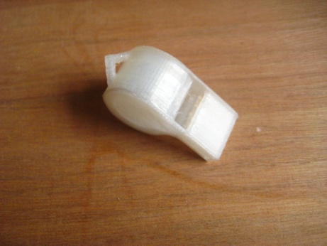
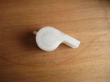
To print it i imported it into replicator-g, centered the object and issued a put on platform command. Then i generated the nessacary G-code and pre-heated the machine. When the preheating was finished i just uploaded the g-code and used the default settings to print it in PLA. Sadly i lost the printed model and i the pictures were on my phone that got stolen... I do however still have the first 3d print i made so i can show a picture of that: the illusive thingiverse Wistle!
This week i made the hello.txrx.45 board. By this time making and soldering the board was self-explanatory. I loaded the c-file in to avr-studio in a new project tailored for the attiny45. I wanted to try uploading Neil's code via avr-studio to see if it would work. Oddly enough it didn't... The code compiled just fine and uploading worked without a problem. But the code just didn't work. At first i thought it might have been a wrong fuse setting but the only fuses that could have screwed it up was the "clkdiv/8" setting (which divides the clock by 8) whick is set by default by avr-studio. Another problem i encountered was that i was unable to run the python program for this board on windows. within windows i can run the program but i cannot run it with the serial port condition the program requires. I even briefly tried to modify the program to hard code my serial port to the program, but my knowledge of python is insuffiecent to get that to run. In the end i just switched to using avrdude on ubuntu and that solved everything. But i would have been nice to have run the python script in windows since then i could keep using avr-studio without switching between operating systems.
One of the main reasons i wanted to use Avr-Studio is that i bought a Atmel Dragon isp. It's a nice little programmer board that enables you to program your board via a isp header (it also has jtag and a HV programmer section) and it allows you to debug your program using DebugWire. DebugWire is a protocol made by Atmel to communicate with your board while the program is running via the reset pin. It allows you to set break-points in your code (the code stops at a certain point) and it allows you to watch variables and their values without using a serial connection. I also allows you to directly set and look at all the registers on the chip which makes it a very powerful tool for debugging your code.
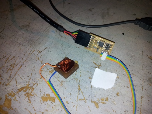
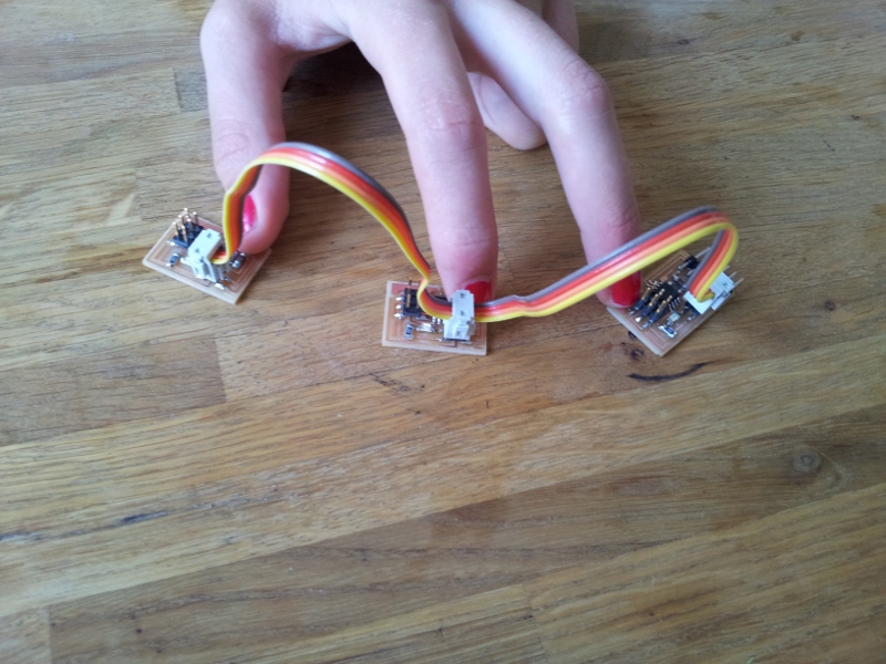
Anyway in the end i uploaded the code in ubuntu using avr-dude. This worked right away. it occured to me that by placing a piece of polyurethane between the 2 plates i could measure pressure. Also by hitting the top plate harder made the reading spring up higher than just softly hitting it. This could be a great way of implementing a velocity sensitive button with aftertouch (like they use drumpads on audio-samplers). So next week i'll try to implement a hello.txrx.45 to midi patch in pd or max/msp.
Picture of my test setup
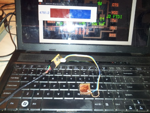
Picture of the py program running
Also take a look at my embedded programming section for an example of reading an accelerometer.
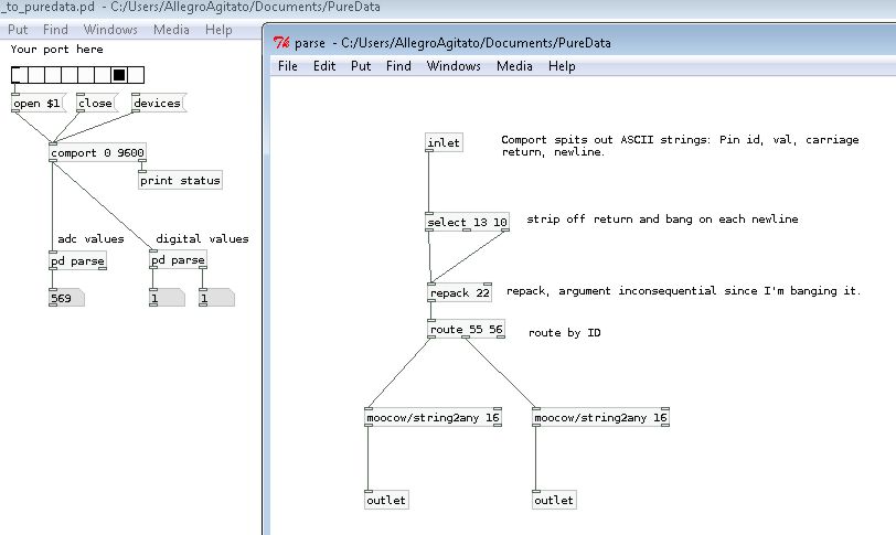
for this assignment i made a patch in puredata and a arduino sketch that can read the sensor and the buttons from the board i made for the embedded programming class. Puredata is an open source graphical programming language mainly intended for generating and processing audio but can be extended to do graphics too. The commercial version of this program is called Max/Msp and is made by Cycling 74.
The patch works a following: the microcontroller reads the pins then sends a ascii string made up of: the pin Id, pin read value, a carriage return and a newline. The receiving patch then takes this string and strips the carriage return and newline and then passes only the pin id and pin read value thru. If a strin does not contain a carriage return and a newline, the string will be ignored. The remaining data (pin id and pin read value) gets sent thru and is routed according to it´s pin id and only the pin read value will be passed along to it´s corresponding outlet.
below you will find a screenshot of the sketch with the left parse subpatch opened. Notice that the argument values are all Decimal ascii values
The arduino sketch can be found below.
#include <SoftwareSerial.h>
/*
This is the code which reads data off the adc and digital pins
and then prints the pin id, pin read value followed by a carriage return and a newline.
*/
//setup sorftware serial on pin# 0 and 1:
SoftwareSerial mySerial(0, 1);

int temp; // temporary integer to store pin values

//Pin setup to easy values:
int adcPin1 = 7;
int digPin0 = 2;
int digPin1 = 3;

void setup(){
  mySerial.begin(9600); // start software serial and set baud rate

  pinMode(adcPin1,INPUT);
  pinMode(digPin0,INPUT);
  pinMode(digPin1,INPUT);
}

void loop(){
  temp = analogRead(adcPin1);
  mySerial.print(adcPin1);
  mySerial.println(temp,DEC);

  temp = digitalRead(digPin0);
  mySerial.print(digPin0);
  mySerial.println(temp,DEC);

  temp = digitalRead(digPin1);
  mySerial.print(digPin1);
  mySerial.println(temp,DEC);

  delay(10); // delay 10ms to settle adc.
}
and the PD patch can be found here.
The nice thing about this sketch is that you can easily adapt it to have a for loop reading all the pins and send the data to puredata. The puredata patch can easily be adapted to read more pins and the nice thing is it does not discriminate between digital pins and analogue pins. It just displays it´s read value.
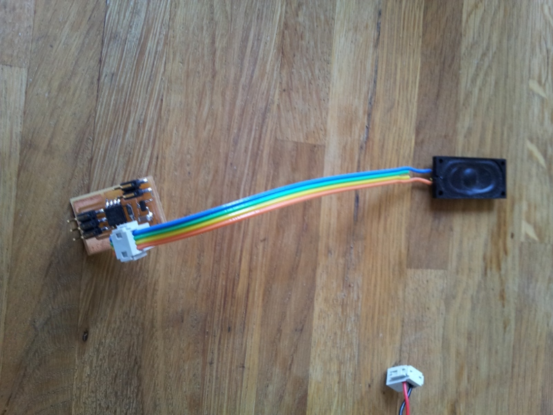
This week i've played around with the h-bridge, the stepper and the speaker board. I've got them all working (which is nice) and i've made some custom code for the hello.speaker board. I've made a function called SingleNote() where you can enter the Note you want to play (lower case for normal, upper case for sharp), the Octave and the duration in milliseconds. And the function will take care of the rest. The code is a bit bulky and it might be better to program a lookup table in an array and have the notes correspond to the note numbers of midi, but anyway this works just fine. The code as is will play a famous childrens song.
This is the code i made:
/*
 * Code taken from http://web.media.mit.edu/~leah/LilyPad/07_sound_code.html
 * Modified and extended for the fab hello.speaker board by Thomas Hopman
 * 18-04-2012
 *
 * For a chart of the frequencies of different notes see:
 * http://www.phy.mtu.edu/~suits/notefreqs.html
 */


int speakerPin = 1; 	// speaker connected to digital pin 1

void setup()
{
         pinMode(speakerPin, OUTPUT); 	// sets the speakerPin to be an output
}

void loop() 	                            // run over and over again
{ 	  delay(1000);

          SingleNote('c',5,21);             // call the SingleNote() funtion // char note (upper case for sharp notes), int octave, long duration in milliseconds
          SingleNote('e',5,21);             // The loop plays a famous childrens song over and over and over and over...... the first "note" is an example of how to make a "chord"
          SingleNote('g',5,21);             // using a monophonic arpeggio.
          SingleNote('c',5,21);             // other ways of getting different sounds (like percussive) would be to modulate the pitch upward and downwards to get kick, tom or "raygun" sounds.
          SingleNote('e',5,21);             // having a function that can play random noise (as far as possible with a 1 bit output) would be nice to make snare or cymbal sounds.
          SingleNote('g',5,21);             // these suggested functions are not implemented as of yet....
          SingleNote('c',5,21);
          SingleNote('e',5,21);
          SingleNote('g',5,21);
          SingleNote('c',5,21);
          SingleNote('e',5,21);
          SingleNote('g',5,21);
          SingleNote('c',5,21);
          SingleNote('e',5,21);
          SingleNote('g',5,21);
          SingleNote('c',5,21);
          SingleNote('e',5,21);
          SingleNote('g',5,21);
          SingleNote('c',5,21);
          SingleNote('e',5,21);
          SingleNote('g',5,21);
          SingleNote('c',5,21);
          SingleNote('e',5,21);
          SingleNote('g',5,21);

          SingleNote('d',5,500);

          SingleNote('e',5,500);
          SingleNote('c',5,500);
          SingleNote('c',5,500);
          SingleNote('d',5,500);
          SingleNote('e',5,500);
          SingleNote('c',5,500);
          SingleNote('e',5,500);
          SingleNote('f',5,500);
          SingleNote('g',5,1000);
          SingleNote('e',5,500);
          SingleNote('f',5,500);
          SingleNote('g',5,1000);
          SingleNote('g',5,250);
          SingleNote('a',5,250);
          SingleNote('g',5,250);
          SingleNote('f',5,250);
          SingleNote('e',5,500);
          SingleNote('c',5,500);
          SingleNote('g',5,250);
          SingleNote('a',5,250);
          SingleNote('g',5,250);
          SingleNote('f',5,250);
          SingleNote('e',5,500);
          SingleNote('c',5,500);
          SingleNote('c',5,500);
          SingleNote('g',4,500);
          SingleNote('c',5,1000);
          SingleNote('c',5,500);
          SingleNote('g',4 ,500);
          SingleNote('c',5,1000);


          delay(1000); 	// delay for 1 second
}

void beep (unsigned char speakerPin, int frequencyInHertz, long timeInMilliseconds)     // the sound producing function
{
          int x;
          long delayAmount = (long)(1000000/frequencyInHertz);
          long loopTime = (long)((timeInMilliseconds*1000)/(delayAmount*2));
          for (x=0;x<loopTime;x++)
          {
              digitalWrite(speakerPin,HIGH);
              delayMicroseconds(delayAmount);
              digitalWrite(speakerPin,LOW);
              delayMicroseconds(delayAmount);
          }
}

void SingleNote (char note, int octave, long length )
{
  if(octave == 4)
  {
          if(note == 'c')
          beep(speakerPin,1046/4,length); //C: play the note C (C5 from the chart linked to above) for length-ms
          if(note == 'C')
          beep(speakerPin,1108/4,length);
          if(note == 'd')
          beep(speakerPin,1174/4,length); //D
          if(note == 'D')
          beep(speakerPin,1244/4,length);
          if(note == 'e')
          beep(speakerPin,1318/4,length); //E
          if(note == 'f')
          beep(speakerPin,1396/4,length); //F
          if(note == 'F')
          beep(speakerPin,1479/4,length);
          if(note == 'g')
          beep(speakerPin,1567/4,length); //G
          if(note == 'G')
          beep(speakerPin,1661/4,length);
          if(note == 'a')
          beep(speakerPin,1760/4,length); //A
          if(note == 'A')
          beep(speakerPin,1864/4,length);
          if(note == 'b')
          beep(speakerPin,1975/4,length); //B
  }
  if(octave == 5)
  {
          if(note == 'c')
          beep(speakerPin,1046/2,length); //C: play the note C (C5 from the chart linked to above) for length-ms
          if(note == 'C')
          beep(speakerPin,1108/2,length);
          if(note == 'd')
          beep(speakerPin,1174/2,length); //D
          if(note == 'D')
          beep(speakerPin,1244/2,length);
          if(note == 'e')
          beep(speakerPin,1318/2,length); //E
          if(note == 'f')
          beep(speakerPin,1396/2,length); //F
          if(note == 'F')
          beep(speakerPin,1479/2,length);
          if(note == 'g')
          beep(speakerPin,1567/2,length); //G
          if(note == 'G')
          beep(speakerPin,1661/2,length);
          if(note == 'a')
          beep(speakerPin,1760/2,length); //A
          if(note == 'A')
          beep(speakerPin,1864/2,length);
          if(note == 'b')
          beep(speakerPin,1975/2,length); //B
  }
  if(octave == 6)
  {
          if(note == 'c')
          beep(speakerPin,1046,length); //C: play the note C (C6 from the chart linked to above) for length-ms
          if(note == 'C')
          beep(speakerPin,1108,length);
          if(note == 'd')
          beep(speakerPin,1174,length); //D
          if(note == 'D')
          beep(speakerPin,1244,length);
          if(note == 'e')
          beep(speakerPin,1318,length); //E
          if(note == 'f')
          beep(speakerPin,1396,length); //F
          if(note == 'F')
          beep(speakerPin,1479,length);
          if(note == 'g')
          beep(speakerPin,1567,length); //G
          if(note == 'G')
          beep(speakerPin,1661,length);
          if(note == 'a')
          beep(speakerPin,1760,length); //A
          if(note == 'A')
          beep(speakerPin,1864,length);
          if(note == 'b')
          beep(speakerPin,1975,length); //B
  }
  if(octave == 7)
  {
          if(note == 'c')
          beep(speakerPin,1046*2,length); //C: play the note C (C5 from the chart linked to above) for length-ms
          if(note == 'C')
          beep(speakerPin,1108*2,length);
          if(note == 'd')
          beep(speakerPin,1174*2,length); //D
          if(note == 'D')
          beep(speakerPin,1244*2,length);
          if(note == 'e')
          beep(speakerPin,1318*2,length); //E
          if(note == 'f')
          beep(speakerPin,1396*2,length); //F
          if(note == 'F')
          beep(speakerPin,1479*2,length);
          if(note == 'g')
          beep(speakerPin,1567*2,length); //G
          if(note == 'G')
          beep(speakerPin,1661*2,length);
          if(note == 'a')
          beep(speakerPin,1760*2,length); //A
          if(note == 'A')
          beep(speakerPin,1864*2,length);
          if(note == 'b')
          beep(speakerPin,1975*2,length); //B
  }

}

void scale ()
{

          beep(speakerPin,2093,500); 	//C: play the note C (C7 from the chart linked to above) for 500ms
          beep(speakerPin,2349,500); 	//D
          beep(speakerPin,2637,500); 	//E
          beep(speakerPin,2793,500); 	//F
          beep(speakerPin,3136,500); 	//G
          beep(speakerPin,3520,500); 	//A
          beep(speakerPin,3951,500); 	//B
          beep(speakerPin,4186,500); 	//C

}
20120815 092432 from thomas hopman on Vimeo.
Some suggested improvements could be:
We did not have a MTM to work on, so i decided to work on my final project. Which also has mechanical design!
For this assignment i've built the hello.bus and the hello.bridge boards. All the boards were functional after a few small problems. At first i just could not get the boards up and running.
Since i upload the code using Avr Studio 5 i need to manually set the settings of Neil's makefile. It is possible to use an external makefile in avr studio but up until now the standard settings in Avr Studio have worked for me. The things i usually set up manually in avr studio are:
Normally this is all that is needed to get the code up and running on the device, but not this time. I did not even got the led flashing on my boards. After looking at neil's makefile if found that he did not use any optimization and as i turned out i was using an optimisations setting of -Os to optimise for size. Turning of the optimization all together resulted in an error telling me there was not enough space on my device. This was strange since Neil's makefile does not specify optimization. After a little trail and error i found that using the -O1 setting worked.
See Final Project page
See Final Project page
See Final Project page
See Final Project page
last updated 18 April 2012