My Final Project - BOOM CHIX
Product Description
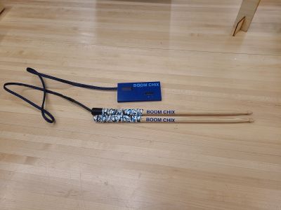
BOOM CHIX is a set of drum sticks to be used with either a drum kit or drum pad to practice stick control and rudimentary drum exercises at the beginner and intermediate levels. BOOM CHIX will consist of a pair of wooden drum sticks made of oak, hickory, or maple that are equipped with a standard metronome module as well as a device to offer haptic feedback or vibration at the same rate as a metronome. Standard equipment during practice sessions consists of drumsticks, ear plugs, headphones, metronome, sheet music, etc. Most drummers and their instructors are concerned with protecting their hearing as long term exposure to the noise created in a musical performance setting can result in hearing loss in the long term. As result, drummers are encouraged to wear both ear plugs and headphones which makes the metronome difficult to hear. Current metronomes usually exist as a wholly separate device so this product will allow for the elimination of an extra piece of equipment while helping to protect the drummers ears. Furthermore, the haptic feedback module, will allow the drummer to feel a vibration in the hand for each BPM rather than have them listen for a click of the metronome. By combining the metronome feature and haptic feedback features the drummer will no longer have to carry a separate metronome and doesn't have to worry about hearing the metronome as they benefit from tactile training instead. They can then spend more time listening to the music and instrumentation while making the practice of the music tempo a tactile experience. With BOOM CHIX drummers won't just hear the music...they'll feel it too!
Solution to a Pesky Problem
It is quite common for beginner drummers to use removable silicon handles to have a better grip and to avoid dropping their sticks. I believe this can be used as a template for a 3D printed handle which can be made out of hard plastic and potentially house the electronics for the vibrating metronome to be built inside. I believe a larger version of this silicon handle can be created once we do the module on molds and casting to fit over the 3D printed handles.Digikey also has a very large inventory of multivibrators which is something I am currently researching in order to find the smallest version possible so that it can fit inside the housing of the drum stick handles. The metronome type electronics kit seem to be way too large for this project unless the machinery is housed a separate unit and wired to the sticks externally which was my initial idea. After some thought I believe it would be much more effective to have everything housed internally.


2D and 3D Modeling
Initial Pencil Sketch Week , 2D Sketch Using Inkscape & 3D Rending of Promark Drumstick


Planned Construction
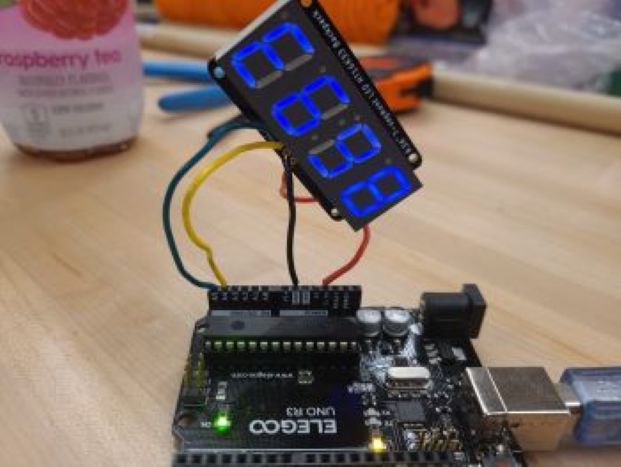
After testing several motors I've decided to go with the ERM motor as it seems to have the stronger vibration and takes up less space inside the drum stick of the two options. It was recommended from the global evaluator that I couple the motor with a transistor on the development board so I will be designing a new with a new shape that will better compliment the look of the final prototype. As 5/20 I have all the parts needed for the project. The LED pictured above turned out to be a voltage meter so that was returned and replaced with a 4 digit Adafruit blue LED display. The current development board has lots of extra space so it will be redesigned to be much smaller with a more convenient button layout.

Beginning to Prototype
I experimented with the silicon drum handles in the photo above but it seems once they are placed over a set of drumsticks they are very difficult to remove so I've ruled those out. I was originially hoping this would create an encasement for the motor which would have a soft feel for the hands. Another option to try was drum stick tape and that is much cheaper and very easy to remove in the event that repairs would be needed. I also ordered a shrinkable wire covering to cover the two wires that will run from the drumstick to the development board while connected to the button motor inside the stick.
I also began to fiddle with cutting into a drumstick and was able to figure out it would be best to use a maple stick instead of oak. The oak wood is much harder and quite to difficult to cut into. I initially was using a 5V rotary tool which turned out not to be powerful enough so I am currently in search of a battery for a 20V Bauer rotary tool.


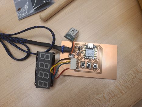
It seems that I can use the motors from the week we did on output devices however I will need to have about 4 feet of cord for the prototype. I also created a new development board with the Xiao RP2040 microcontroller and a 3 digit digital display. I added 3 buttons so that one button would power on and the other two would function as up and down to increase bpm. I will begin to work on the coding soon to see which adjustments need to made to the components. I also experimented with 3d printing an encasement for the board. So far I have made the bottom, experimental of course but I just wanted to revisit the skills I had learned in Fusion 360 for 3d design.


Prototyping the Chord
I am creating the chord that will run from the development board to the motor inside the drumstick. I am using a 2 wire multiconductor cable in red and black ad will use the black wire to connect to ground on the microcontroller. I spliced the ends of the wires on the red and black ribbon to expose about 1/2 inch. I then did the same to the blue and red wires on the ERM motor. I cut a lenght of 4 feet for the red and black ribbon cable as that would give enough room for the user to freely move while the stick is connected to the control system. I then soldered the connections and secured them with shrinking wire covers to protect and insulate the connection. I then ran the ribbon wire with connected motor through a shrinking cable cover enclosure of a slightly shorter length to allow clear connection to the circuit board without interference. I then used the hot air nozzle at the soldering station to shrink the wire covering around the red and black ribbon cable.


Attaching the Chord & Adding 3D Printed Motor Cover
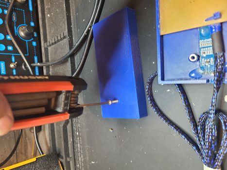
I first attempted to hollow out a portion of the drum stick using the Bauer rotary tool pictured above. While I thought that would be the main tool, it ended up being used as secondary support. In our lab I found a cutting power tool called an oscillating multi-tool and that seemed to cut things much more efficiently. I learned how to use the tool during the build something big assignment where we used it to cut the tabs created by the CNC machine. I did the majority of the cutting with the oscillating tool and the remained was done by using a rotary blade at an angle to chip away the cuts made by the oscillating tool. I continued to hollow the drum stick until the ERM motor on its cord fit inside with room to spare. Once the opening was big enough I used 3M Brand 220 Grit sand paper to sand the inside of the groove to make sure the stick was smooth and free of splinters.


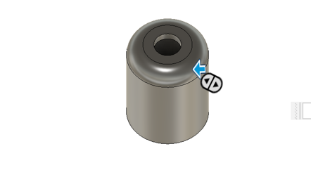
Next I decided to design a cover for the motor and hollow opening using fusion 360. The purpose of this cover would be to keep the drumstick grips that would be added from sinking into the hollow area on the stick. I used a digital caliper to meaure the length and the width and my first print was too small and also too thin. I adjusted the measurements so that the cover would be thicker, curved, and slight overhang the opening to make it a smoother transition.
The second print in white was the perfect size, so with the ERM motor and cable placed inside the hollow of the drum stick I sealed the opening with the 3D cover using two small dots of hot glue. In this way it would be simple to remove to make repairs.


The drumstick grip tape that I ordered from Amazon needed to be cut to fit the sticks that I am using. One piece of grip tape was long enough to wrap both sticks with a little left over to spare. I removed the protective film on the grip tape to reveal a rubberized non slip grip in a blue, white, and black camouflage color. The grip tape comes with built in double sided adhesive but the adhesive did not stick well so I used double sided tape from the lab to reinforce the grip tape's connection to the stick. I was sure to measure them so that the two sticks would appear to be a part of the same set; same length and same thickness regardless of which stick would have the motor. I used one dot of hot glue from a hot glue gun to seal the final edge of the grip to the stick for smooth finish.


Final Adjustment to Drumstick Hollowing
My instructor suggested that if I used a lathe to create a hollow space for the drumstick that the finished product would not only look neater but also the motor would have a more snug fit without touching the sides of the hollowed out space. I was able to find a drill bit that was roughly same width as the ERM motor and used the lathe to drill a tunnel into the drum stick that was about 1.25 inches deep. This would allow the weighted end of the ERM motor to rotate without hesitation. With this machine several tool such as wrenches and keys are used and each part requires something different. The most important safety instruction for this machine is to be sure that hair, loose clothing, etc are removed or tied back. Remove all jewelry as well because. It is also important that you remove any wrenches and all oversized allen key type tools from the machine before turning it on. Both the wood being cut and the collet on the drill head should be tightened into position before turning the machine on. The end result was a very neat hollow opening and huge improvment over the one I had drilled with the oscillating rotary tool a few days earlier.
I was under the impression that by having a snugg fit that the fibration would be stronger but it actually seems the vibration was stronger with the larger hollowed out spaces. When running sitting on the work bench the ERM motor bounces back and forth on anything it runs to and I imagine that would create a tacticle effect as well. I think that perhaps a larger hole drilled a wider drill bit may work out better.


Development Board Adjustment
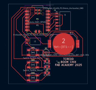
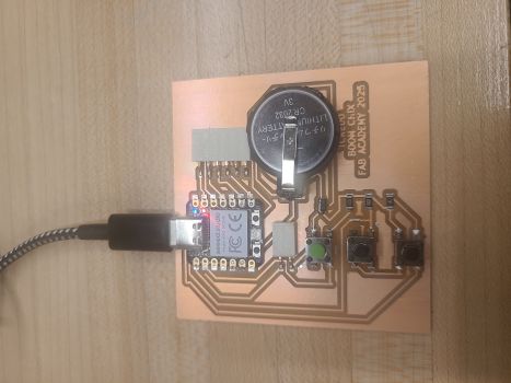
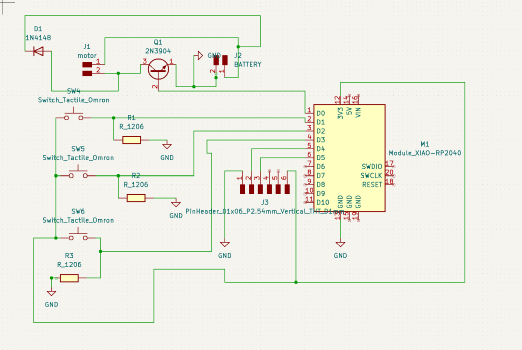
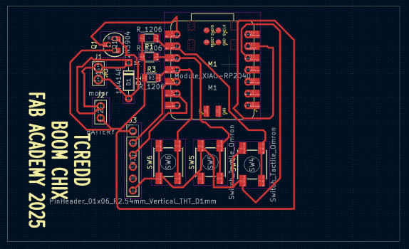
To avoid having issues with overloading the board with current it was suggested that I use a transistor. I chose to use the 2N3904 in addition to adding a diode 1n5822. I also chose to power the motor with a 3.7V Lipo Lithium battery which is rechargable. The motor would be powered by the battery but the LED display would be powered by the Xiao RP2040. I had to completely redesign the development board as a result and so this time around chose to drill through holes that would allow for "easier" soldering which turned out not to be the case at all. I ended up losing many of the traces to the soldering iron or by moving wires that tore the traces. Some of them on the final attempt I was able to repair using copper wire and an exacto knife to add the traces back in.
The newest version of the development board moved away from the 3 Volt CR2032 batter and instead the motor is being powered by a 3.7 Volt Lipo Lithium battery. This change was made to take full advantage of controlling the current when motor is present. To the original design at this point a transistor,pull down resisters, and a diode have been added
Adafruit 4 digit LED and OLED with I2C Connection
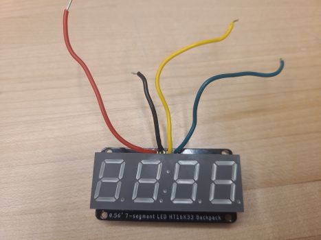
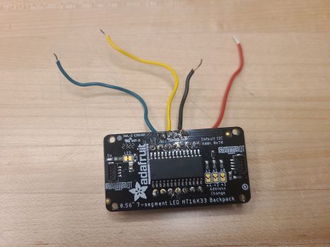
My initial plan was to have a 4 digit LED to display the number of beats per minute on the metronome. I purchased the Adafruit 4 digit LED directly from Adafruit. Was able to get it working with the Arduino Uno at 5V but was unable to get it to power up with Xiao RP2040 connected to the 3V3 pin. I was able to download the Adafruit GFX and the Adafruit SD1306 from the Arduino IDE library in order to test the power of the LED on both boards. The code that I used tested the board for serial connection and also verified that the board was connected in general. The photos below show the code and files are below in the design files.
Getting the Adafruit LED display prooved to be a challenging task using the I2C connection. When I did a search on google I found that this was a very common problem with the Xiao RP2040. I visit the Seeed Studio forums and it seems that many who were a little more tech savvy suggested to edit the Xiao Program at line 68. It was also mentioned by many that the process to do so isn't straight forward.
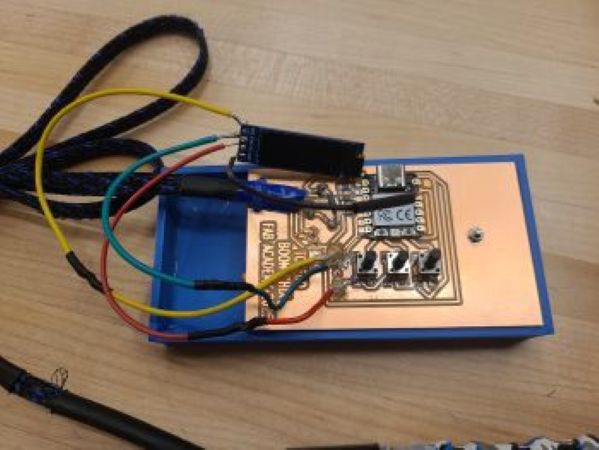
I then moved on to a much smaller OLED display that was 0.91 inches as it seems that some people have had more luck with that model. It required downloads of the Adafruit GFX package to the Arduino Library as well. Unfortunately the same occurred with this screen as well. When running the code to check if the board is connected, the Arduino IDE recognizes the I2C device but will not power it up. I returned to the seeed forum and found many others had posted having problems as well. I didn't want to overlook that the problem might be with the screens. My instructor suggested that I connect the screens to the Arduino Uno and they worked fine on that board. I also ran a beep test with digital multimeter to see if perhaps there was short or an overlap of the wire traces or solder on the development board. I checked each connection and used the hot air nozzle to clean up any stray solder but the board was in very good connection with clear and clear contact from the microcontroller. The motor worked as output connected to the board but the digital displays would not.
One post on the Seeed Forum suggested trying out the Seed Studio round touch screen display as it specificially designed to connected to the Xiao, in piggy back fashion, pin for pin. I believe this will help solve the issue as it will not only eliminate wires, but also it will eliminate buttons and give the option for visual output in the form of timer, clock, or a pulsting image. When the new screen arrives I will see if the dirct Xiao connection fixes the problem.
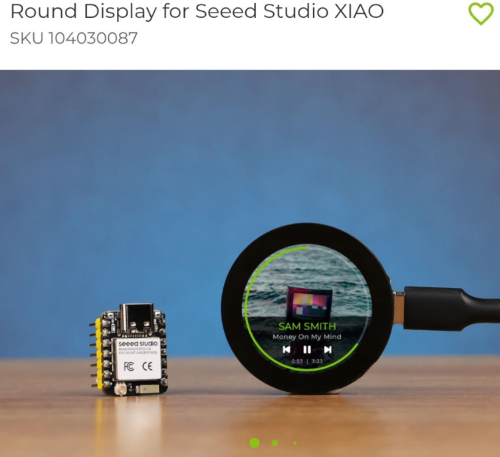
The screen in particular plays a very important role in the functionality of the product. Without the display the user is unable to see how many BPM the machine is set too. They can quickly use the buttons to either increase or decreas the BPM but my idea is to have the display show the number of BPM as well as how long the metronome will vibrate for.
Motor Challenges and Defects
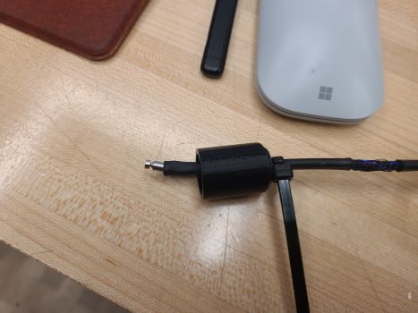
The ERM motors are so tiny and they are designed to have two super thin wires which seems to only an hour or two of use (off and on). They are incredibly difficult to strip or splice because the size. I found myself extending the length on these to keep the motor from breaking off. For the next iteration I added newly cut jumpers from a thicker wire to be soldered to the thin wires. To further protect the motor wires I was sure to anchor all connections so there was no way of putting tension on the motor wires. I did this by cutting holes in the circuit board and tying down the cable just before it leaves the plastic inclosure in addition to doing the same on the drum stick end. It was secured into place by adding a small plastic encasement with a cable tie on the interior to make sure the cord could not be tugged or accidently torn out of the motor encasement.
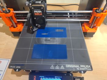
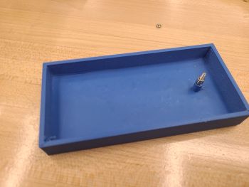
3D Printing the Plastic Case
I used a Prusa MK3 and blue PLA filament to create the exterior case to house the circuit board, wires, and screen. Both pieces are identical in dimension and used a hole in a cylinder on Fusion 360 to create a screw hole that could be used to attach the two pieces together at 2 differnt points on either side of the circuit board. I was able to use an allen key to tighten the screws. On one side I used a digital caliper to measure the length and with of the 0.91 inch screen and the slot to fit the 3 tactile buttons. I did end up printing the bottom portion 2x as I forgot to allot measurement for the thickness of the walls on the case as I hollowed the drawing in fusion 360.
Testing the Metronome and Making Calculations for BPM
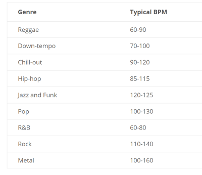
I took a look at many of the songs in my music library using DJuice DJ software that I have on my personal computer. I thought it was a good place start as it displays the typical beats per minute for most songs in my library. I also searched further on google and landed on a web page Musical U and found the average tempos for many different genres of music. See the table below. The table would help me to decide the range of BPMs to target for my final product. I specifically did a search for music that is not played electronically so that I could know for sure that them tempo could be matched by a human and not a computer. It is common for new drummers to exposed to many different genres as they all offer exposure to different techniques and foundational rudiments.
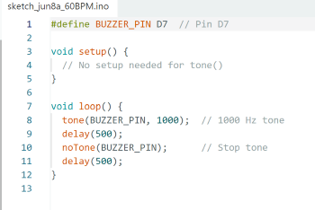
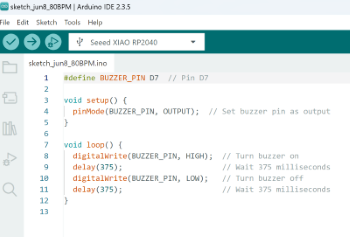
I first tested the code in Arduino IDE to make sure the motor would vibrate using the development board I had created. I tested it at 30BPM. Below are the table of typical BPM measurements for different genres of music in addtion to the test code for making the ERM motor vibrate using code from Arduino IDE. It is the same code I used in Week 6 output devices. I decided to test code for 60-80-100-120 BPMs. This would give me a wide range of music genres but would also allow me to test the vibrations of the ERM motor to figure out how long each vibration should last both for vibration and quiet interval in between the vibrations.
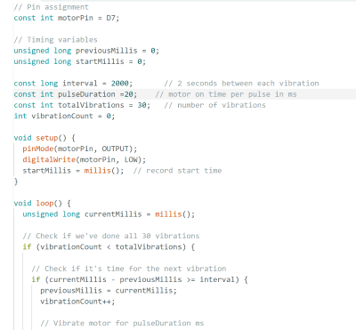
Code to Test Different Tempos
Since the product is designed for mostly newer drummers I decided to focus on the range from 60 BPM to 120 BPM. It covers a wide variety of music for the newer drummer and also takes into consideration that much of todays music is electronic. I used a google search to find the code to test 60-80-100-120 so that I could hear the difference but also see how the quiet intervals in between the vibrations would feel to the hand. This was important to make sure the drumstick would vibrate continuously and then more intensely. I programmed it to make vibrations and then silence in between. Pictured below are screenshots of how the code changes across choosing different tempos.

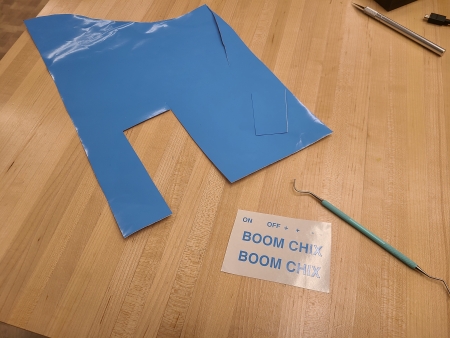
Vinyl Cutting
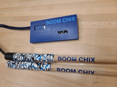
I placed BOOM CHIX logos made of blue vinyl on both the sticks and on the plastic casing. I intentionally made them the same size so that they would appear more like authentic logos. I used the U.S. Vinyl Cutter and the software "Sure Cuts A Lot" to make letters that were approximately 0.5 inches in height. They were quite easy to weed out and I used white transfer tape to move the letters to both the stick and the plastic casing.
Current Model
The current model contains a 3.7V Lipo Battery to power to the motor. I soon found out after that if I redesign the board the LIPO battery can power the entire product. The 3D printed casing is very small but can be made a bit smaller with the new screen. In order to finalize code it will be necessary to use the new screen which is on order. The final code will program the LED to display the BPM on the display as well allow the user to increase the tempo or decrease the tempo using buttons. The user will also be able to power the unit off and on using a button as well.
The final product was created with the OLED screen that I could not get to function. I've ordered the round Seeed Studio touch screen that was manufactured specifically for the Xiao RP2040 In the meantime I've created the code for the final product which may have to be adjusted slightly based on the placement of the new screen. I can also cut a new board that will eliminate the buttons which will allow the final board to be much smaller and closer to the real thing. I will also power teh entire outfit with 3.7V Lipo Lithium Battery so the entire thing will not have rely on the Xiao RP2040 for power.
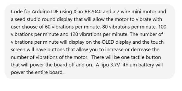
Code for Metronome using New Screen & 2 Fewer Buttons
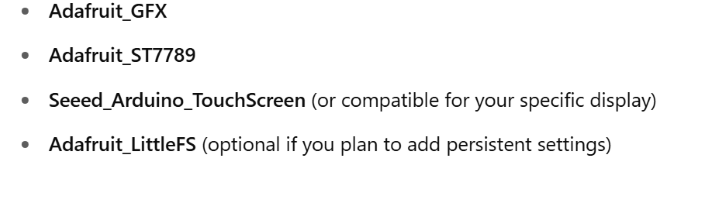
ChatGPT Search Prompt & Libraries Needed
Code Generated by Prompt
#include
#include
#include
#include

// Display pins (adjust if needed)
#define TFT_CS   7
#define TFT_DC   6
#define TFT_RST  5

Adafruit_ST7789 tft = Adafruit_ST7789(TFT_CS, TFT_DC, TFT_RST);

// Motor control pin
#define MOTOR_PIN 10

// Tactile button pin for soft reset (on/off)
#define POWER_BUTTON_PIN 2

// Touch screen instance (update values if your touch library differs)
TouchScreen ts = TouchScreen();

// Available vibration rates (in vibrations per minute)
int rates[] = {60, 80, 100, 120};
int currentRateIndex = 0;

// Vibration timing control
unsigned long lastVibrationTime = 0;
unsigned long vibrationInterval = 1000;  // will be calculated from rate

// Motor state
bool motorOn = false;

// Power button state
bool lastButtonState = HIGH;

void setup() {
  pinMode(MOTOR_PIN, OUTPUT);
  digitalWrite(MOTOR_PIN, LOW);

  pinMode(POWER_BUTTON_PIN, INPUT_PULLUP);

  tft.init(240, 240);
  tft.setRotation(0);
  tft.fillScreen(ST77XX_BLACK);
  tft.setTextSize(2);
  tft.setTextColor(ST77XX_WHITE);

  updateDisplay();
  calculateInterval();
}

void loop() {
  handleTouch();
  handlePowerButton();
  runMotor();
}

void runMotor() {
  unsigned long currentMillis = millis();
  if (motorOn && currentMillis - lastVibrationTime >= vibrationInterval) {
    // Pulse motor
    digitalWrite(MOTOR_PIN, HIGH);
    delay(20);  // motor pulse width in ms
    digitalWrite(MOTOR_PIN, LOW);

    lastVibrationTime = currentMillis;
  }
}

void handleTouch() {
  TS_Point p = ts.getPoint();
  if (p.z > 0) {
    if (p.x < 120) {  // Left half = decrease rate
      if (currentRateIndex > 0) {
        currentRateIndex--;
        calculateInterval();
        updateDisplay();
        delay(300);  // simple debounce
      }
    } else {  // Right half = increase rate
      if (currentRateIndex < 3) {
        currentRateIndex++;
        calculateInterval();
        updateDisplay();
        delay(300);  // simple debounce
      }
    }
  }
}

void handlePowerButton() {
  bool buttonState = digitalRead(POWER_BUTTON_PIN);
  if (buttonState == LOW && lastButtonState == HIGH) {
    motorOn = !motorOn;
    updateDisplay();
    delay(500);  // debounce
  }
  lastButtonState = buttonState;
}

void updateDisplay() {
  tft.fillScreen(ST77XX_BLACK);
  tft.setCursor(40, 80);
  tft.print("Rate: ");
  tft.print(rates[currentRateIndex]);
  tft.println(" BPM");

  if (motorOn) {
    tft.setCursor(70, 140);
    tft.print("Motor: ON");
  } else {
    tft.setCursor(70, 140);
    tft.print("Motor: OFF");
  }
}

void calculateInterval() {
  vibrationInterval = 60000 / rates[currentRateIndex];
}
Final Materials List
| Qty | Description | LinkPrice | |
|---|---|---|---|
| 1 | 7 Pairs Maple Sticks | Promark Maple Drum Sticks Size 5A | $16.95 |
| 1 | Drumstick Grip Tape | 6pk Drum Stick Grip Tape | $13.48 |
| 1 | 17 pk Miniature Button Motor | 17 pk Vibrating Mini Motor 3V | $6.99 | 1 | Expandable Wire Sleeving | Wire Sleeving Blue and Black | $8.99 | 1 | Ada Fruit 4 Digit Display w/ Backpack | Adafruit 4 Digit Blue LED display | $11.95 | 1 | Seed Studio Round Display | Seeed Studio Round Display | $18.00 |