(Output) Mobile Module - PCB design
Write something at the front
What I want to achieve is that when this board receiving the message from my reComputer, it can display my calendar and meanwhile doing something, like controling a relay.
Thus, for my output PCB design board, I will have one ILI9431 display integrated. Since the display is heavy, and the pins are all arranged on one side.
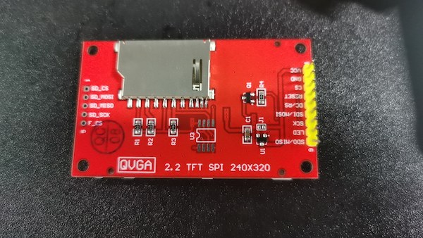
It has 8 connectors and I will have one PinHeader_1x08_P2.54mm_Horizontal_SMD for connecting it. And then I will have a Grove connector, for connecting other modules.
Design PCB on the KiCAD
I measured the connectors on the display and it quite fit. But the Grove connector is not well, I might need more resource for that.
Any way, I first check the principle of the display and connect them one by one to the XIAO:
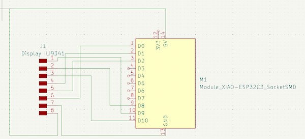
Then I add one Conn_PinHeader_1x04_P2.54mm_Vertical_THT_D1mm as Grove connector represented. But the parameter seems not quite fit(this is later I known).
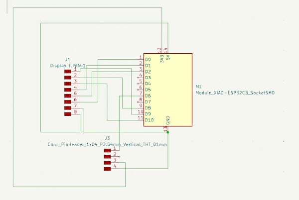
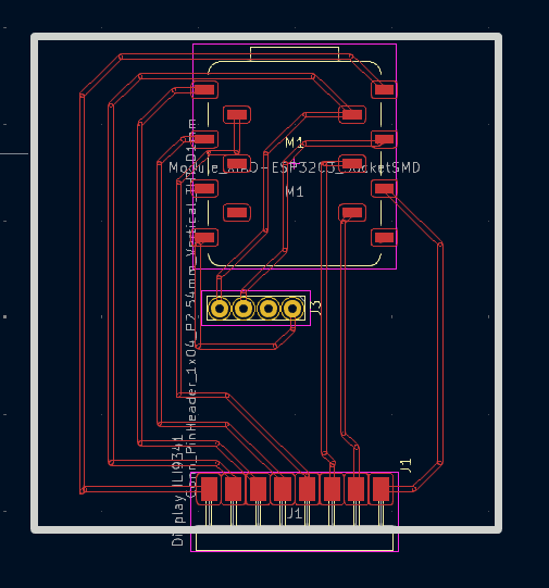
In order to walk the line more easily, to adjust the back and forth. This is final version:
Hence the display code will be:
#define TFT_CS     A0
#define TFT_RST    A2
#define TFT_DC     A1
#define TFT_MOSI   10
#define TFT_CLK    8
TFT_LED connector just connect to a HIGH level Pin 9.
And the signal connecotor of Grove is connecoting D6, or 21.
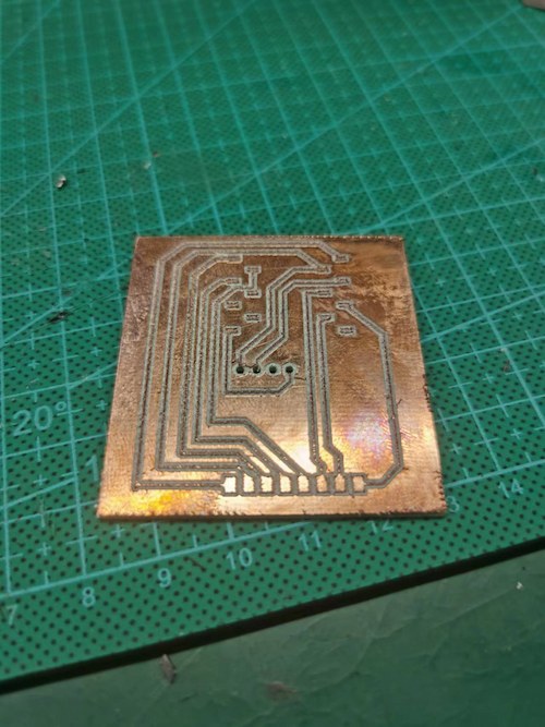
I refer to the previous setting up from week8, and milling:
The board is done:
And after soldering:
Front:
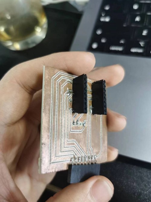
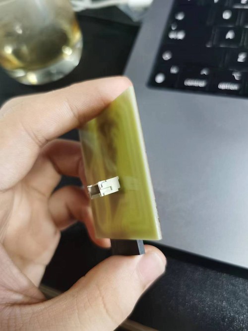
and back:
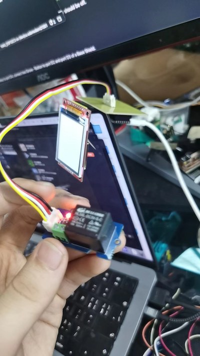
Connection Check
Read the serial port and display text
Here is the code:
#include <SPI.h>
#include <Adafruit_GFX.h>    // Core graphics library
#include <Adafruit_ILI9341.h> // Hardware-specific library

// 定义使用的引脚
#define TFT_CS     A0
#define TFT_RST    A2
#define TFT_DC     A1
#define TFT_MOSI   10
#define TFT_CLK    8
#define TFT_LED    A3   // 如果不控制背光,可以忽略这个引脚或始终保持为HIGH

// 初始化Adafruit ILI9341
Adafruit_ILI9341 tft = Adafruit_ILI9341(TFT_CS, TFT_DC, TFT_RST);

void setup() {
  Serial.begin(9600); // 初始化串口通信,设置波特率为9600
  pinMode(TFT_LED, OUTPUT);
  digitalWrite(TFT_LED, HIGH); // 开启背光

  tft.begin(); // 初始化屏幕
  delay(1000);
  tft.setRotation(1); // 根据需要设置屏幕方向

  // 清屏
  tft.fillScreen(ILI9341_BLUE);

  // 设置文字颜色和背景颜色
  tft.setTextColor(ILI9341_RED, ILI9341_BLACK);

  // 设置文字大小
  tft.setTextSize(2);

  // 在屏幕上显示 Hello World!
  tft.setCursor(0, 0); // 设置文本开始的位置
  tft.println("Hello World!");
}

void loop() {
  // 检查是否有串口数据可读
  if (Serial.available()) {
    // 读取串口数据
    String input = Serial.readStringUntil('\n');

    // 在屏幕上显示读取到的数据
    tft.println(input);
  }
}
Turn on Relay
Here is the code
// Relay Control

void setup()
{
  pinMode(D6, OUTPUT);
}

void loop()
{

    digitalWrite(D6, HIGH);

}
Now I can move to the case design.