17. Invention, Intellectual Property and Business Models
Code
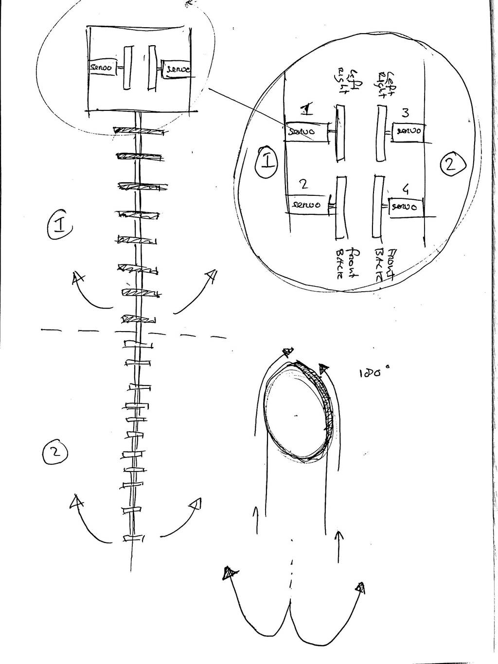
To set the servos in the right start position I use this code. I you don’t hold the joystick it goes to its original middel postion.
#include <Servo.h>
Servo servo1;
Servo servo2;
int joyX = A0;
int joyY = A1;
int joyVal;
void setup ()
{
  servo1.attach(10);
  servo2.attach(9);
}
void loop()
{
  joyVal = analogRead(joyX);
  joyVal = map (joyVal, 0, 1023, 0, 180);
  servo1.write(joyVal);
  joyVal = analogRead(joyY);
  joyVal = map (joyVal, 0, 1023, 0, 180);
  servo2.write(joyVal);
  delay(15);
}
This is the code I use to control 4 servos
#include <Servo.h>

Servo servo1;
Servo servo2;
Servo servo3;
Servo servo4;

int joyX1 = A0;
int joyY1 = A1;
int joyX2 = A2;
int joyY2 = A3;

int joyVal;

void setup ()
{
  servo1.attach(6);
  servo2.attach(5);
  servo3.attach(10);
  servo4.attach(9);
}
void loop()
{
  joyVal = analogRead(joyX1);
  joyVal = map (joyVal, 0, 1023, 0, 180);
  servo1.write(joyVal);
  joyVal = analogRead(joyY1);
  joyVal = map (joyVal, 0, 1023, 0, 180);
  servo2.write(joyVal);

  joyVal = analogRead(joyX2);
  joyVal = map (joyVal, 0, 1023, 0, 180);
  servo3.write(joyVal);
  joyVal = analogRead(joyY2);
  joyVal = map (joyVal, 0, 1023, 0, 180);
  servo4.write(joyVal);
  delay(15);
}
Building
I thought it would take me not so long to make this Octo. I took me two days.....
This inpired me though. I want to make the Octo in different parts so I can easily update all the part individiually. But first let’s check what I’ve made and what I should take into account in the following Octos.
This Octo. It exist out of 4 servos that each control two directions. The tail is devided in to seperate parts. The first part is controlled by two servos and the second part aswell.
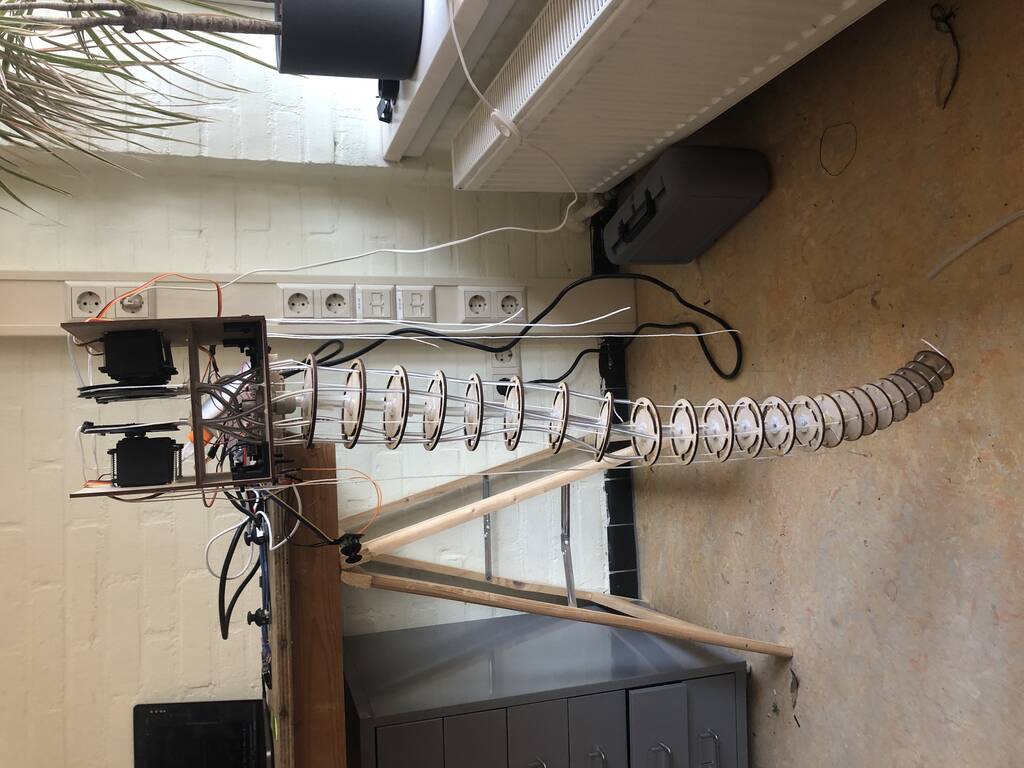
First only 2 servos worked. But not smooth. I check everything. Switched pins new code, etc.
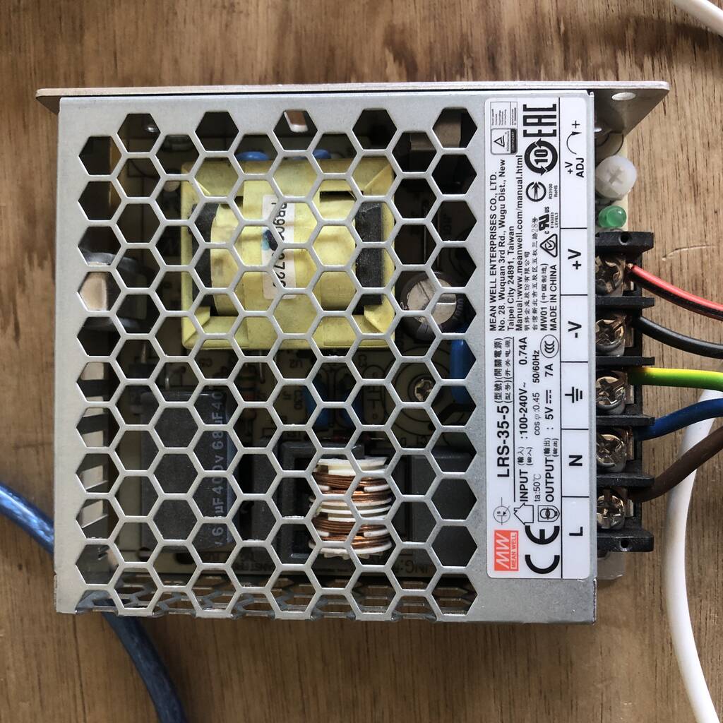
But then I remebered that these servos pull quite some ampere. So I connected this badboy and the arm worked nice:)
Is 7 amps not to mucht though. The arm pulls quite some power out of these motors…
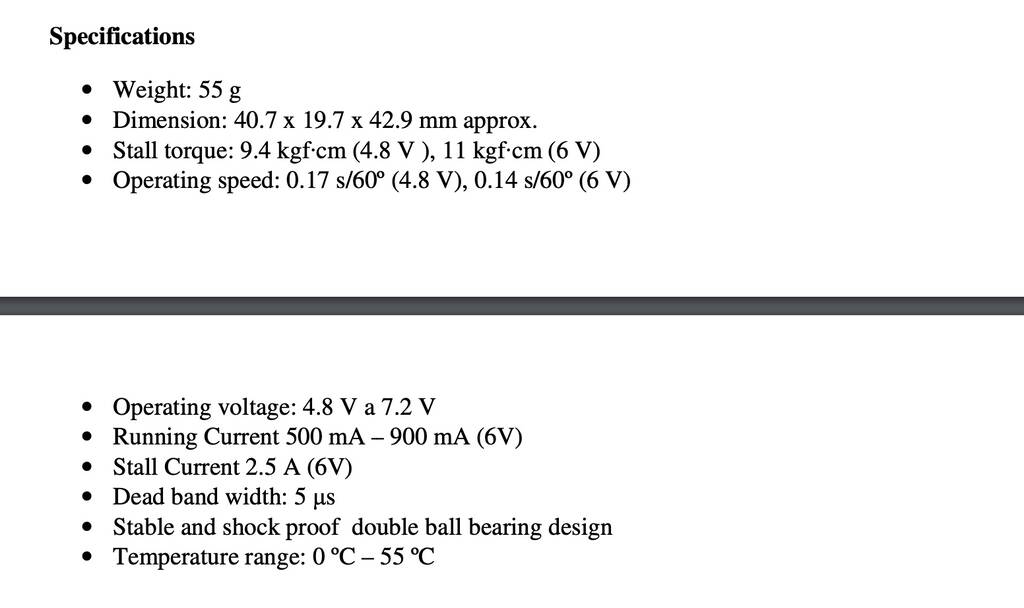
The stall current is 2.5 Amps (6V). 7A / 4servos = 1.75A. So I’m save.
2.5 amps is the stall current from the centerpoint of the motor. I have a pulley 65mm. So I’m not save.
Here you see it works.
So what should I take into account in making my final model?
The pulley clamps do not work efficient and I don’t trust them if I’ll use them a lot.


The cable housing has a really small diameter and it takes a lot of effort to get my thread in. I stabbed my hand a couple of times with the iron thread to get the plastic thread through. I should experiment with some other thread and other cable housing (when i have time, this is not priority)


The core is flexible. But unfortunately also in the rotation direction. I don’t want that.
List of things I should change
There are a lot of thing I want to change about Octo. Octo will never be finished. But these are thing I’ll change.
- other housing
- other thread
- other core
- other pulley clamp
Modular Octo
Octo will never be finished. So I want to make Octo modular so it will be easy to take octo apart and to make changes. I’ll focus on the beehive principle. I want to attach the arm to the Quintins beehive-axes so I’ll take that design as a starting point.
Quintins beehive-axes
I got this beehive-axes from michelle. Thanks

Some things I need to change


Modeling
Changed a view things on the ........


Wanted to continue with the beehive dimensions but it’s not convenient.


I think this is pretty nice.

Printing
4h 30m with 0.3 layer height

5h 47m 0.3 layer height

1h 32m 0,3 layer height

26 m layer height

Cable gland/clamp
I bought some cable glands but they’re not thight enough.
I need the PG11 for a 10mm diameter core.
It would be cool though if I can 3d print the cable clamps.
Alternative
This one looks cool. PLA breaks easily so nylon filament would be apropiate. Nylon is semi-flexible but verry strong and abrasion resistant.
This guys says Nylon filament will do nicely pla will break easily. We don’t have nylon but we do have PETG which has good phisical properties. Idealy I want something that’s a bit flexible. PETG isn’t but I’ll give it a try anyway.

I also tried this one.
Printed it on 0.15 layer height. Finish is pretty good. But the small part break off easily.


I scaled it but the fingers are way to thin now. Need to remodel. Will do this later, no time now.

I want my filament to have the following filament.
- abrasion resistant
- High tensile strengt (nylon(PA) has 50-80 MPa. Pc has 70 MPa)
-
Adjustments
Cariage
Ballbearings need to be a bit closer. Its a bit loose on the rails.
Changed this from 22.25 to 21.50. So 1.5 mm less space.


This adjustmeent worked. Maybe .5 mm more in total.
Servo holder
Side holes for wire need to be bigger!
Code
Thes 2 links is exactly what I want.
#include <ESP32Servo.h>

Servo myServo;
int servoPin = D0;

void setup() {
  // put your setup code here, to run once:

myServo.attach(servoPin);

Serial.begin(115200);

}

void loop() {
  // put your main code here, to run repeatedly:

//myServo.write(90);

//with this line only 2 commands in serial possible
if(Serial.available()){
    int angle = Serial.parseInt();
    myServo.write(angle);
  }
  delay(20);
}
PCB
Servo

SEED XIAO ESP32-c3

5V - This is 5v out from the USB port. You can also use this as a voltage input but you must have some sort of diode (schottky, signal, power) between your external power source and this pin with anode to battery, cathode to 5V pin.
Servos work without capacitors. But servos draw a lot of current in high peaks. Especially how with how I’ll use the servos. Every servo needs his own capicitor. The capictor should be as close to the load as possible.
I choose for 1 capacitor. The longer lead of the capacitor is the positive lead and this should be connected to 5V. The negative lead is also often marked with a ‘-‘ symbol.


Tryout
If I plug my esp32-c3 in my adapter while its plugged in my board. My voltage devider goes HAM. Because the 5v input is also a 5v output....... I just blew the voltage devider.
The connectors are also pretty stupid design because they’re pretty close to the pins. This can create shorts pretty easily.
The left side works the other side doesn’t. I used this code.
#include <ESP32Servo.h>

Servo myservo1;   // create servo object to control a servo
Servo myservo2;  // twelve servo objects can be created on most boards
Servo myservo3;
Servo myservo4;

int pos = 0;    // variable to store the servo position

void setup() {
  myservo1.attach(D0);  // attaches the servo on pin 9 to the servo object
  myservo2.attach(D5);
  myservo3.attach(D7);
  myservo4.attach(D10);

}

void loop() {

  for (pos = 0; pos <= 180; pos += 1) { // goes from 0 degrees to 180 degrees
    // in steps of 1 degree
    myservo1.write(pos);              // tell servo to go to position in variable 'pos'
    delay(15);                       // waits 15ms for the servo to reach the position
  }
  for (pos = 180; pos >= 0; pos -= 1) { // goes from 180 degrees to 0 degrees
    myservo1.write(pos);              // tell servo to go to position in variable 'pos'
    delay(15);                       // waits 15ms for the servo to reach the position
  }


  for (pos = 0; pos <= 180; pos += 1) { // goes from 0 degrees to 180 degrees
    // in steps of 1 degree
    myservo2.write(pos);              // tell servo to go to position in variable 'pos'
    delay(15);                       // waits 15ms for the servo to reach the position
  }
  for (pos = 180; pos >= 0; pos -= 1) { // goes from 180 degrees to 0 degrees
    myservo2.write(pos);              // tell servo to go to position in variable 'pos'
    delay(15);                       // waits 15ms for the servo to reach the position
  }


  for (pos = 0; pos <= 180; pos += 1) { // goes from 0 degrees to 180 degrees
    // in steps of 1 degree
    myservo3.write(pos);              // tell servo to go to position in variable 'pos'
    delay(15);                       // waits 15ms for the servo to reach the position
  }
  for (pos = 180; pos >= 0; pos -= 1) { // goes from 180 degrees to 0 degrees
    myservo3.write(pos);              // tell servo to go to position in variable 'pos'
    delay(15);                       // waits 15ms for the servo to reach the position
  }


  for (pos = 0; pos <= 180; pos += 1) { // goes from 0 degrees to 180 degrees
    // in steps of 1 degree
    myservo4.write(pos);              // tell servo to go to position in variable 'pos'
    delay(15);                       // waits 15ms for the servo to reach the position
  }
  for (pos = 180; pos >= 0; pos -= 1) { // goes from 180 degrees to 0 degrees
    myservo4.write(pos);              // tell servo to go to position in variable 'pos'
    delay(15);                       // waits 15ms for the servo to reach the position
  }


}
Used this new code but the same problem appeared.
#include <ESP32Servo.h>

Servo myservo1;   // create servo object to control a servo
Servo myservo2;  // twelve servo objects can be created on most boards
Servo myservo3;
Servo myservo4;

void setup() {
  // put your setup code here, to run once:

  myservo1.attach(D3);  // attaches the servo on pin 9 to the servo object
  myservo2.attach(D4);
  myservo3.attach(D0);
  myservo4.attach(D1);

}

void loop() {
  // put your main code here, to run repeatedly:

  for (int i = 0; i < 180; i++) {
    myservo1.write(i);
    myservo2.write(i);
    myservo3.write(i);
    myservo4.write(i);
    delay(10);
  }

  for (int i = 180; i > 0; i--) {
    myservo1.write(i);
    myservo2.write(i);
    myservo3.write(i);
    myservo4.write(i);
    delay(10);
  }
}
Changed the order of the pins. It’s not the servos. Its not the pins. Its not the traces of my board. So I’m pretty sure that it is the amount of Ampere. 3A is not enough for 4 mg996r.
Made a new PCB with a new voltage regulator and a few capacitors to clean the air.
Problem
I know what the problem is. I can only control the first 2 servos in line. I think its the amount of ampere is too little.
Capacitor
A capacitor is a device used to store electrical charge and electrical energy.
The amount of storage in a capacitor is determined by a property called capacitance.
C = The capacitance 𝐶 of a capacitor is defined as the ratio of the maximum charge 𝑄 that can be stored in a capacitor to the applied voltage 𝑉 across its plates. In other words, capacitance is the largest amount of charge per volt that can be stored on the device.
E = E is the start-up energy requirement of the motor (Joules)
V = is the voltage (volts)
Formula: C = E / ( .5 ∗ V2 )
Joules
Joules for mg996R = 11 kgf·cm (6 V) This is the maximum.
F= m * a (gravity = 9.8m/s2)
F= 11 * 9.8 = 107.8 = F
Chat gtp
I found a lot of examples. Not sure which calculation I should work. I asked Chat gtp. And this is what it said:
To determine the appropriate capacitor for your setup with 4 MG996R servos, you’ll need to consider the peak current requirements of the servos and select a capacitor that can handle those brief surges of current.
The MG996R servo is known to have high peak current demands, particularly during sudden movements or when under load. While the datasheet for the servo may provide some guidance, it’s generally recommended to use a large electrolytic capacitor to stabilize the power supply and minimize voltage drops during these high-demand periods.
A commonly recommended value is a 1000μF (microfarad) electrolytic capacitor per servo. Since you have four servos, you can consider using four 1000μF capacitors in parallel to distribute the load. When capacitors are connected in parallel, their capacitance values add up.
Make sure to choose capacitors with a voltage rating higher than your power supply voltage, ideally around 10V or higher to provide a safety margin.
Additionally, it’s essential to have appropriate wiring and connections to handle the high current requirements of the servos. Use thick gauge wires and proper connectors to minimize voltage drops and ensure sufficient current flow.
Remember to double-check the datasheet and guidelines provided by the servo manufacturer for any specific recommendations or precautions regarding the power supply and capacitors.
Result
Due to time and everything I read I’ll go for one 2200 uF - 16 V capacitor. In a lot of examples they used a 470 uF capacitor. Per 3 or 1 servo. So this should do.
Stepper
This link is extremely helpfull.
A4988 stepper driver

12v


Do you understand how this wiring works? I don’t..
There are two options:
- start with black from 1a
- black green in the middle. and red blue at the outside. But you have to keep the same order 1 = - and 2 = + or vice versa.
I’ll go for: start with black and don’t change the order.


Running stepper
Determine current limit.
2 rated current Datasheet
Vref = Current Limit / 2.5 Vref = 2 / 2.5 = 0.8

This explains how to wire the stepper to the driver.


It doesn’t work properly. What can it be.
- tried other motors
- Maybe traces wider
- maybe Vref higher or lower
- Voltage devider is now 5v 100ma. Maybe to 5v 1a. The pcb maybe gets to little power to control the driver
- Use a different code
- Schottky is not right
Symbol link Footprint
I hate this. You have to do the following.
download symbol and footprint. I use Snapeda
Create a new map for your footrint. This file is name_mod

Manage symbol libraries In sketch editor.
And manage footprint librarie in PCB editor.

Import the symbol in sketch editor. Run electrical tool check and click ok. It find the footprint now.
Prepare image
create in F.cu the traces.
Create the oultine (and holes) in margin -> take drill diameter into account.
Open both files in same file in inkscape. Make sure cu is centered in margin. use control shift R to crop canvas.
Save margin and CU separate.
Controller
The XIAO ESP32C3 is capable of using a 3.7V lithium battery as the power supply input. You can refer to the following diagram for the wiring method.

| type | amount | link |
|---|---|---|
| tactile swith | 4 | link |
| Slide switch | 1 | link |
| Led green | 1 | link |
| Resistor 100 ohm | 1 | link |
| 3.7 battery | 1 | link |
| Joysticks | 2 |
Joystick needs 5 volt?
Since I’m using a 3.7 lithium battery. I’ll power the joysticks with 3.3 instead of 5v. Hopefully this won’t give any trouble.
Checked if the buttons work with this code
int pushButton = D6;

void setup() {

Serial.begin(9600);

pinMode(pushButton, INPUT);

}


void loop() {

int buttonState = digitalRead(pushButton);

Serial.println(buttonState);

delay(1);

}
Ground poor kicad
Place
add filled zone
select GND
CLick B on the keyboard
everytime you make a new adjustment in the PCB design click B
Which resistor for the LED
LED
Voltage - Forward (Vf) (Typ) 2.2V
Current - Test 20mA
3.7V to 2.2 V
The forward voltage of a LED is 2.2V (check with the manufacturer). Forward current 20mA, so - using Ohms law, 3.7V battery - 2.2V LED = 1.5V and 1.5/.020 = 75 Ohms.
75ohm resistor
Power source
The MG996R motor has stall Torque of 9.4 kgf·cm at 4.8V and 11 kgf·cm at 6V. The operating Voltage of this motor is 4.8V to 7.2V.
Assignment
assignment
develop a plan for dissemination of your final project
prepare drafts of your summary slide (presentation.png, 1920x1080)
and video clip (presentation.mp4, 1080p HTML5, < ~minute, < ~10 MB)
and put them in your root directory
Desseminmation
It would be nice to make a git page that’s dedicated to Octo with all the models and clear explanations how to make Octo yourself.
Get famous on Hackers / Hackaday, instructables, etc.
Make a nice tik tok and instagram video. <- this is actually a good starting point for the video.
Summary slide and video clip
