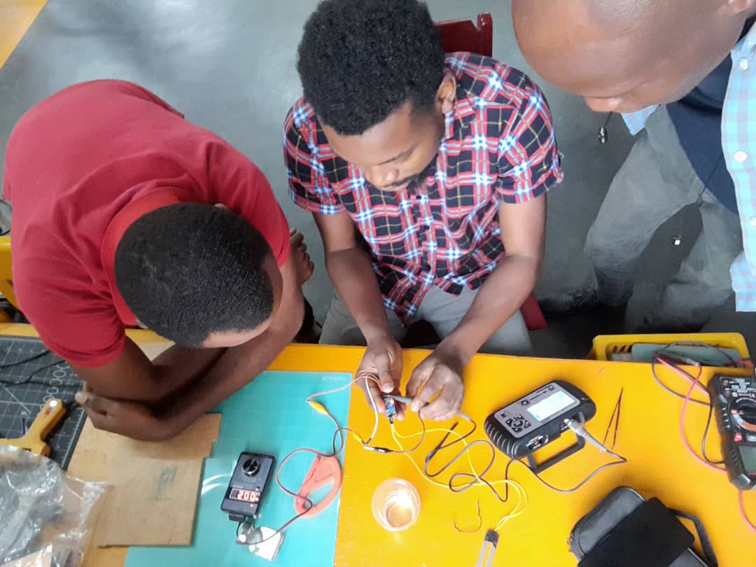
group assignment: probe an input device’s analog levels and digital signals
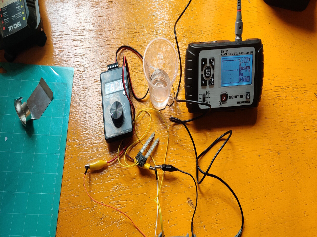
To begin probing, connect the ground clip of the oscilloscope probe to the ground reference of the input device. This ensures a common ground reference between the oscilloscope and the device being measured. Then, carefully attach the probe tip to the signal you want to measure.
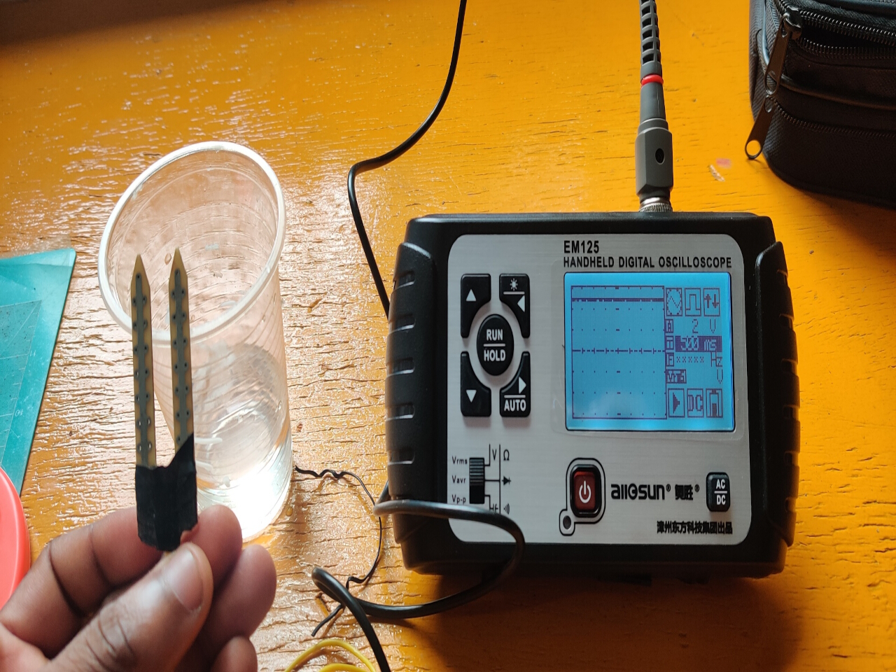
For analog signals, adjust the oscilloscope’s settings to capture the appropriate range and time scale. This may involve setting the vertical scale to match the amplitude of the signal and adjusting the timebase to capture the desired time period. By observing the waveform displayed on the oscilloscope’s screen, you can analyze the voltage levels, frequency, amplitude, and any distortions or noise present in the analog signal. Analog signals may represent continuous variations, such as audio waveforms or sensor outputs.
For digital signals, ensure that the oscilloscope is set to the appropriate triggering mode, such as edge triggering. Digital signals are typically characterized by discrete voltage levels, such as logic high (1) and logic low (0). Adjust the vertical scale and timebase to properly display the digital waveform. The oscilloscope will display the voltage transitions, rise and fall times, pulse widths, and other timing characteristics of the digital signal. This information can help diagnose issues like signal integrity problems, jitter, or timing violations.
When probing digital signals, it’s important to ensure that the oscilloscope’s bandwidth and sampling rate are sufficient to accurately capture high-frequency digital signals without aliasing or distortion.
It’s worth noting that proper handling of the oscilloscope probe, correct signal connections, and consideration of the probe’s loading effects are essential to ensure accurate measurements and prevent interference or damage to the input device or oscilloscope. Always refer to the oscilloscope and input device’s user manuals for specific instructions and precautions when making measurements.