8. Electronics Production
This week I worked on creating my board from Electronics Design Week, by milling, masking and soldering the gerber files I designed. While my end boards didn't end up working, I do end up creating successful micro-controller based boards in the Output Devices Week, which you can view the documentation on that process there. Here I only detail the processes and workflow for the ESP32s2 dev board I started 2 weeks ago.
View our group documentation on characterizing our pcb mills here!
|
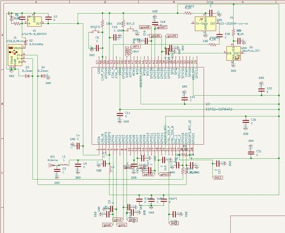
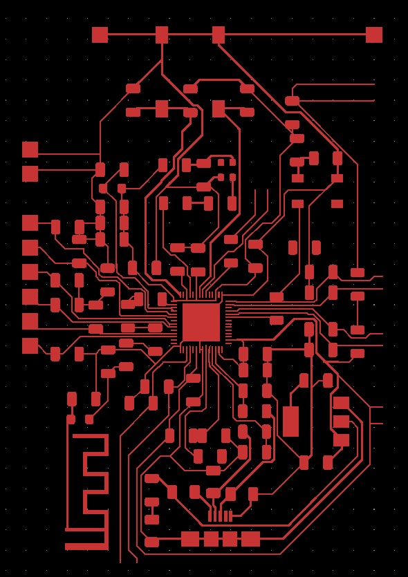
ESP32s2 Dev Board
|
||||||
| Setting up the PCB Mill |
|
|---|---|
|
Our mill already had the pcb bracket in place, so all I needed to do was make sure the bed was flat and clear of any debris.
To do this, I used the shopvac to suck up the small FR1 dust from previous mills, and peeled off any residual double-sided tape.
If you discover that the pcb bracket is not there, you will have to go through the process of installing it, and detecting it using the back side of an end-bit through software.
|

|
| I then selected my FR1 board, based on the size of my pcb I wanted to mill. Basically it has to be large enough to accommodate the height and width of your board, plus sum extra for wiggle room. I just used a new piece of FR1, since it can fit up to 4 of my ESP32s2 Dev Boards. I applied Nitto tape to the back of the board, and placed it on the bed - lined up with the pcb bracket. You need to make sure it stays very flat and lined up at this stage, or you will have issues with extra-large trace clearances and the mill bit not reaching as far down as it needs (causing uncut traces and shorts). To do this, I used a plastic squeegee to press down and smooth out the pcb to the base plate. |

|
|
To control the mill, I am using the BantamTools software. Start by following the onscreen instructions for uploading your file, changing the bit, and setting up your file placement. After switching the bit, it is important to do a bitbreaker scan to determine the height of the bit. This just needs to be done over an empty spot on the spoil plate. Once you have determined the height of the bit, you can then connect your board using the moving tab on the front of the pcb bracket. The tab should touch the copper of the board - electrically connecting it to the base of the mill. You then should do a z-stock probe to determine the actual height of your material. Note: in some cases, where you probe can give you different heights - this is due to the boards not being perfectly flat. The best solution for this would be to incorporate the use of a G-code editor to include automatic levelling. An okay solution is to navigate the bit to hover over the middle area you are cutting, and doing your z-stock probe there in hops to take the most-middle or median height of your board. I went with this quick option. |


|
| Milling Your Board |
|||
|---|---|---|---|
|
Once you have set up your material, selected your bit, and calibrated your mill, you can upload your gerber files to the Bantam Tools software.
It is okay if you chose the wrong bit before, as it will prompt you to change the bit before each cut.
You can use multiple different bits to cut different widths, thus speeding up processing time, or increasing the detail level.
Since my board was fairly complex, I used a 0.1mm 20˚ V-bit for the trace cutting, since this is a fairly small bit that can fit between smaller clearances.
I also used a 1/32" flat end-mill to do extra trace clearing, as well as cutting out the board.
You can adjust the trace clearance and depth, and observe the predicted outcome in the viewer.
This is incredibly helpful to make sure you are not adding too little clearance, or cutting too deep.
Milling with the V-bit and Flat-endmill: Can do all trace sizes, spaced out traces faster, can cut holes 
|
|
||
Be sure to set your offset, and double-check your board length an position including the offset.
If you cut too close to the pcb bracket, the end mill will more than likely just cut right through it.
This is not good for the bracket, and more than likely will break the bit.
Here is an example of how I was barely off on my offset by a few mm, and ended up breaking a bit, and the pcb bracket screw.


|
|||
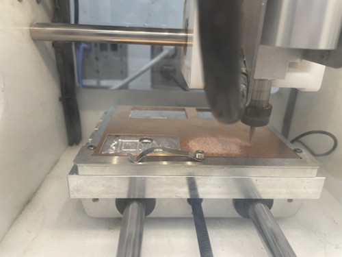
| After you have set up your board mill, calibrated the axis, and generated the gcode - you can attempt to mill your board. If you have multiple tools selected, it will force you to change your bit before cutting if it doesn't match. Follow to onscreen instructions to do so. While my board is milling, I usually sit close by to listen to the machine. Any abrupt loud or grinding sounds should indicate something may be wrong, and your process needs to be paused and assessed for the causation of the error. |
|
||


| Milling Results |
|
|---|---|
|
The First Mill
Issue: Uneven board caused the V-bit to dig too deep in some areas (such as around the chip), and in some parts caused the V-bit to not cut all the way through the copper layer (such as the antenna). |


|
|
The Second Mill
Issue: Was perfect, until I went to cut it out. The carriage got uncalibrated and caused it to cut too high up the board. |

|
|
The Third Mill
Issue: Had some burs, and some traces weren't cut deep enough. I went through with an Xacto knife to cut the traces all the way. I sanded the board a bit to get rid of the burs, then used alcohol to clean and prep it up for the solder mask. |


|
| Applying the Solder Mask |
|
|---|---|
|
To make soldering easier, and to protect the board, I wanted to try using a UV curing solder mask.
Having to deal with ripped traces and bridging is not fun, and using a solder mask actually helps reduce both of these occurrences significantly.
To apply it, all it requires is squeezing a glob of it onto the board, then spreading it out evenly. I first used this roller to spread out the mask, and it worked. The main issue with this is while the mask is pretty even, it's a little rough. Plus, a lot of excess resin gets stuck on the roller, causing you to use more mask than necessary. |

|
|
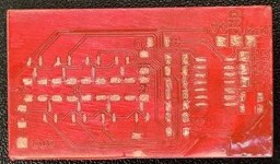
On another board, I tested using my red uv resin. Not only did it look cooler, it seemed to cure faster.
I did the same process on this board, but instead of the roller I used a plastic squeegee.
This made a very smooth and even coat, with minimal wasted resin left on the squeegee.
I then used the UV curing station for our SLA printers, and it cured after about 30 minutes.
After curing, I used an Xacto knife to remove the mask on the traces. Otherwise, I wouldn't be able to solder the components to the board! The lower example on the right isn't the board I used for this week, but it shows the same trace clearing result. Note: Please don't make the same mistake I did, and do your continuity testing BEFORE solder-masking. The solder mask makes it harder to cut bridged traces, and requires you to scratch off a layer before you can actually put your multimeter probe onto the trace. |

|
| Soldering the Board |
|
|---|---|
|
The first board I made, with the green mask, didn't end up working.
I had not done continuity tests first, so after I had soldered in most of the components and tried to power it, it didn't work since there were some shorts.
I tried cutting traces, in hopes to find sources of shorts, then rerouting the paths using jumper wire.
After many hours of this, I decided it would probably be a better idea to just redo the board.
I milled out another board, and this one seemed to come out pretty solid, with only a few shorts here or there. I did the continuity test on this board before solder-masking, and was able to isolate all the traces. This time around, I was able to solder everything up, with only a few shorts here or there, which I fixed with jumper wire. In the end, it didn't work, I think this is because there were shorts between ground and important pins on the ESP32s2 chip. It was at this point after a lot of debugging, I decided to move more of my electronics production week to also encapsulate parts of the output devices week. You can read up on the custom DAC I made using a 1614 here. |

|