This week, I am using the opportunity to use the Shopbot to create a coffee table for my living room - which is currently lacking one.
You can view our group work of characterizing the ShopBot parameters here.
My fiancée and I have been needing a table to have near our couch while we work on things and for movie snacks.
I attempted to create a design that was somewhat modern, but also modular so it can be improved upon in the future.
One main component is the pocket hole in the middle of the table. This will allow me to add whatever I want for the top of the table.
I am considering pouring resin or using some nice and thin planks of wood to improve its look.
While those final details are still up in the air, I had a good time designing and putting this table together.
Below you can find an outline of my process:
I started by drawing a blank slate of the material I am working with (4'x8' 1/2" plywood).
This helps me get an idea of scale required for this project. I am using Fusion360 to draw this.
I drew some rough ideas, until I found a shape that I liked. I incorporated a brim to allow for future customization, and removable triangulated legs.
The legs can be removed easily for transportation. They are angled to help give more support than a strictly perpendicular leg.
I added crossbeams to the legs to help with potential wobble, and used square tab inserts to connect the brim to the tabletop.
After constructing each component, I put it together 3-dimensionally to make sure each part would fit, line up, and that I liked the outcome.
After I verified the design and was pleased with it, I exported the sketch file to a .dxf so I could pull it up and prep if for the ShopBot using Aspire.
Final Sketch:
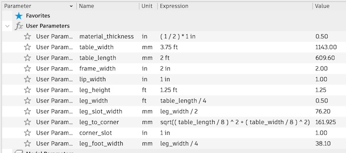
Here are my parameters:
Prepping the Cut
Now that I have my table designed, I am ready to upload it into aspire to generate the toolpaths.
I went to go check out the wood sheet Tom had procured for me, but unfortunately someone had already taken a good cut right in the middle of it!
So, I had two options - find a new piece, or resize my table. I decided to go back into fusion to resize my table to 2' x 3.5', which is honestly a lot better of a size for our living room.
The original 5' table would have been enormous in comparison.
The new parameters:
The plywood in question:
Creating Tool Paths with Aspire
I took my exported DXF file of my table and imported it into Aspire - which is a program that is used to develop toolpaths for cnc machines.
I set my material width to 1/2", and the tool as a flat 1/4" endmill. I set the number of passes to 4, to ensure a smooth cut.
I then added dog-bones to the areas where pieces slot together, to help give it extra wiggle room in the corners.
I also added tabs every 8 inches to keep the cut out pieces secure while being milled.
Once the toolpath looked good, I exported the toolpath as a ".crv3D" file and loaded it into the ShopBot software.
Running the Shopbot
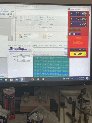
Shopbot Software
After creating the Tool Path with aspire, you can export it to run on the ShopBot software.
To control the spindle, to move it out of the way or to home it, you can use the following list of commands to do what you need:
Using the J3 (jog x,y,z) command, move the spindle to the far side of the bed, so you can place your material flat onto the shopbot.
I secured mine using plastic nails that were injected using a pressurized air-gun.
This prevents the sheet from being moved by the spindle as it carves through the material.
After the board is flat and secured onto the bed, we can calibrate the spindle height using the calibration pad placed below the end-mill.
This can be done using the ZZ (zero Z-axis) command.
Using the JZ (jog z-axis) command, I offset the bit by about 2 inches from its home position.
When running the cut, this causes the machine to do air-cuts, which avoids cutting any of the material.
This can be used for inspecting how the machine will move in the x and y directions, to verify that it keeps the bit on the material area, and doesn't deviate elsewhere.
Be sure to stay close to the red stop button, to engage it, should any issues occur while the machine is in use.
After verifying my air-cuts looked good, I went ahead and started the cut with no offset.
It seemed to be cutting well - no grinding sound, while still being very loud, and no hang ups or splintering wood.
Here is the first cut of the tabletop. It appears to have done the inside holes first, then the outside cut for the whole table top.
Watch it making the cut here!
Mistakes While Cutting
The first issue that occurred happened on the LAST PIECE being cut.
The end-mill bit fell out of the collet mid-cut.
I am not sure if the collet was not tightened enough - since it cut fine for an hour before this.
Or, if the collet is just slowly loosening from continued use.
I am guessing fixing the former would address the latter, but I am not totally sure on to what extent.
After replacing the bit, and recalibrating the machine, I set up a new cut for that last piece on Aspire.
This was where my second mistake occurred - I had accidentally set it to cut the inside of the vector path, as opposed to the outside.
This ended up wasting a bit of wood by the time I realized what was happening.
Luckily, all I had to do was reposition where the leg would be cut, and change the pathing to the outside of the vector.
(Notice on the right how the right leg is skinnier than the left due to the inside cut.)
Putting the Table Together
I composed the top of the table with 3 main components:
The Rigid Base - with mounting holes and provides main surface of table
4 Side Frames - to add depth, with mounting grooves on both 45 degree tapered ends
4 Square Locks - just wooden squares to shove into the mounting holes and grooves to hold them all in place
Unfortunately, it seemed like the cuts I did for the squares to fit into were a bit too wide.
I attempted a method to remediate this by wrapping tape around it to increase its width.
This seemed to work well, but was not an ideal solution.
I ended up gluing them in place, along with the frames to the base - since in hindsight attempting to hold wooden beems in place with only the ends seems a bit foolish.
There was bound to be warping. In fact, if you look at the beem on the top image on the left, you can see it has a slight bend in it.
This ended up being a similar case with the legs and crossbeams.
To fix this, I glued and clamped them all together as well.
This definitely isn't a great solution to hold the beams and legs together, but it definitely adds some stability as opposed to not adhering the beams securely to the legs.
I think some sort of inserted joint would be a better solution to this.
The legs were glued into the inner mounting holes on the main.
This seemed to fit really well considering the glued beams. I locked these in with wood glue as well.