3. Computer-Controlled Cutting
|
This week consisted of using the laser cutter and vinyl cutter to create a build kit, and my own custom sticker of my "mascot": Partysquid
View our group work here: Characterizing Laser Cutter Parameters |
![[this should be partysquid]](../images/Week3/newpartysquid_orig.jpeg)
|
| Design File Links |
|
|---|---|
| - Parametric Kit DXF |
|
| - Partysquid Base Image |

|
| - Partysquid Vectorized |

|
Laser Cutter - Custom Shapes Build Kit
To start, I worked on using Fusion360 to create a parametric file to use on the laser cutter.
| Designing the Parametric Kit |
|
|---|---|
|
I started by creating some rough shapes of my ideas for the build kit.
I wanted to build a few pieces that were "useful" to build with, and had their own interesting twist.
I wasn't concerned about making accurate measurements at this step, as I would need to apply parameters to fix them anyways.
In this situation, I felt like it would be time wasted on trying to get accurate measurements before making the parameters.
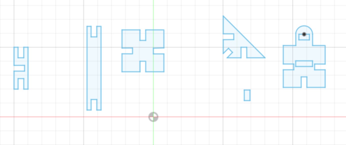
I made:
|
| The gingerbread man shape also comes with a locking rectangle (the small one) which can be used with the hole in the middle of it, and the rounded tab. The locking mechanism can slide into the smaller hole when the rounded shape is pushed through the larger hole of another ginger bread man. This holds it firmly in place, allowing for a plane-plane connection, that are continues, rather than twisted orthogonally like a slot-slot connection would make. You can see a couple examples of the square and short bar shapes to the left. | |
|
Then, I went on to create the parameters by navigating to MODIFY and selecting Change Parameters.
I clicked the + button towards the top of the window, and created new user parameters.
These measurements accounted for:
|

|
|
I at first just filled it with placeholder values of approximations of what I estimated the measurements should be.
I later changed these to the proper measurements once I measured the actual material (3.6mm cardboard) being used on the laser cutter.
Any measurements not based on material thickness, such as the length of the sides on each shape, was changed to be more appropriately sized to the cardboard, and added the kerf.
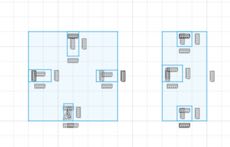
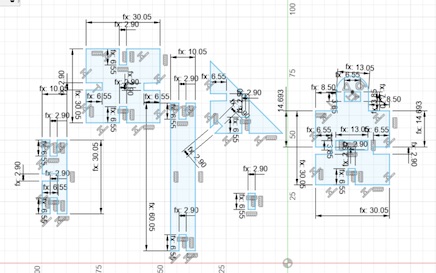
You can view the final plans with and without measurements below: |
|

|
|
| The Laser Cutting Process |
|
|
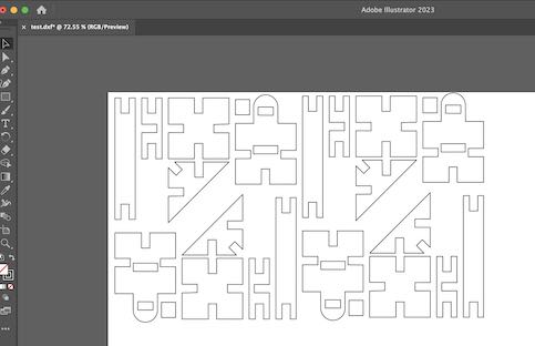
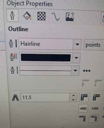
I exported the sketch as a .dxf file by using this tutorial from the Autodesk Knowledge Network. After importing it to Adobe Illustrator (my go to raster software), I rearranged and copy and pasted the shapes into a space-efficient pattern to cut on the laser. I exported it as a pdf, and sent it to the computer connected to the laser via Google Drive. I prepped the file by opening it on CorelDraw, and converting the width of the vector lines to "hairline" as using this setting will default to cutting on the laser, without having to change that setting on Epilog Manager. |
|
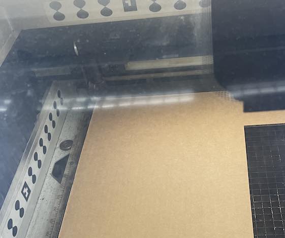
I prepped the cutting area by getting a good sized piece of cardboard and aligning it to the top-left corner.
At this point, I had already measured and applied the correct measurements of the cardboard to the parameters by using calipers.
I found the kerf parameter from our group work,
outlined here.
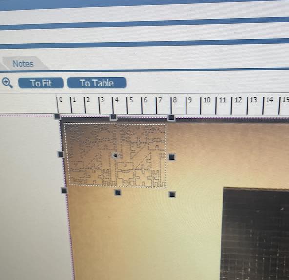
After clicking print on CorelDraw, I used the epilog manager to place my parametric building kit in the top-left corner of the cardboard.
Luckily, our laser has a camera - so it was only just a matter of dragging it to the correct location.
|
|
|
|
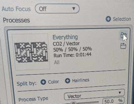
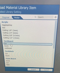
| To make sure I don't burn the lab down, I needed to change the settings of the laser to cut cardboard. I did this by clicking "import material settings" file icon on the right, then selecting "Cut" under "Cardboard". This comes with pre-loaded settings adjusted to cut cardboard on our laser. After that, I sent it over the laser, and began setting that up. |
|
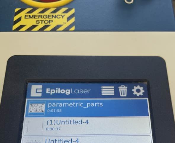
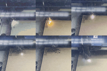
| I focused the laser to the approximate middle of where I was cutting. Then did a trace with the red laser pointer to make sure my cuts would stay on the cardboard - which they did. I selected the correct job - which was conveniently located at the top! I pressed play and let it go! |
|
|
Wow! Look at it go! |
| Some Mistakes |
|
|
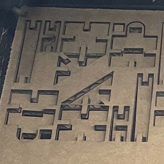
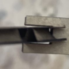
Because the cardboard was slightly warped, some of the pieces would fall underneath the big sheet of cardboard as they were cut out. This would cause issues such as misaligned holes, or a piece risk getting cut if it wedged itself underneath another piece that was getting cut by the laser. One way to prevent this, besides getting a flat piece of cardboard, would be to use weights to help it lay flatter on the bed. If the holes being misaligned was the only issue, I would cut the holes first and then the outside so that way it doesn't get misaligned when it falls before cutting the holes. |
|
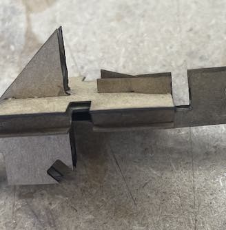
Another issue I encountered was that the pieces were a bit loose at the start. This made it difficult for the constructions to stay together. |
|
To fix this, I added a "snug" parameter as per suggestion from my coworker, Zack, which made the fit a bit tighter.
I subtracted this snug parameter from the slot widths.
Since cardboard is more maliable than other materials, I could set this to a tighter setting since the cardboard can flex a little.
This made the pieces fit together nicely!
|
|

|
|
| Assembling the Kit |
|
|
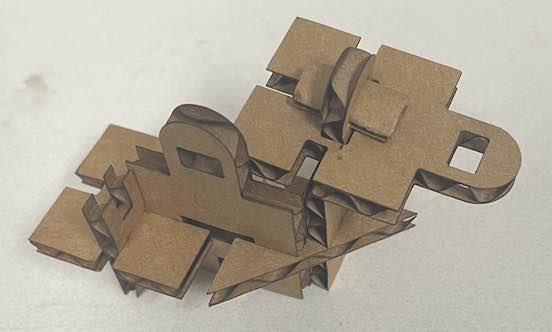
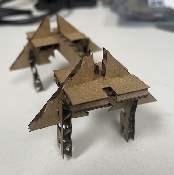
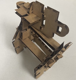
Using the pieces, I could build a variety of designs by press-fitting and locking them together. |
|
I call this one "Long House" due to its long, house shape. |
|
This is "Camel House", since it looks kinda like a house with a weird bump.
|
| Start the bidding at $100,000 for these beautiful homes! | |
Cutting Out the PartySquid Sticker
| The Design Origin | |
|---|---|
The name "PartySquid" was a username I came up with in middle school, and I have used it since for most things.
Funnily enough, I accidentally logged in with my "partysquid" email for my job interview at Latin because of this.
Nonetheless, I made an original design ofpartysquid using GIMP back in highschool - totally raster based.
In college, I learned how to use the Adobe Suite, and recreated and revitalized my old crummy design of PartySquid using Illustrator.
He's all vectors now - which makes it perfect for creating a sticker.
 
|
|
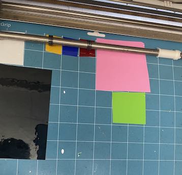
| I wanted the sticker to be approximately 4"x4", so I grabbed a few colors of vinyl that I thought matched the colors of PartySquid fairly well. Using Silhoutte Studio, I split apart his shapes into vector cuts, and positioned them around the grid. I lined up my vinyl on the sticky mat according to where I placed them on the software. This was fairly simple since the software setup had a grid I could compare it to. |
|
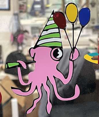
| Unfortunately, I made the mistake of taking the backing off the vinyl, before putting it on the mat. I sent the cuts through and the mistake was brought to my attention after my fellow classmates saw me struggling to put it together. This made it sort of difficult to reconstruct PartySquid, since I had to carefully peel off each sticker with an Xacto knife. I then use the Xacto knife to carefully lay each sticker in the proper position on the black backing. As you can see, this caused some imperfections here or there. I then transferred it onto the transfer paper, and slapped it on the window next to the other FabAcademy stickers. I think it looks pretty good for my first attempt at using the vinyl cutter! |
|