Steppers
This page documents some tests on the stepper driver and stepper motor.
Challenge: time crunch
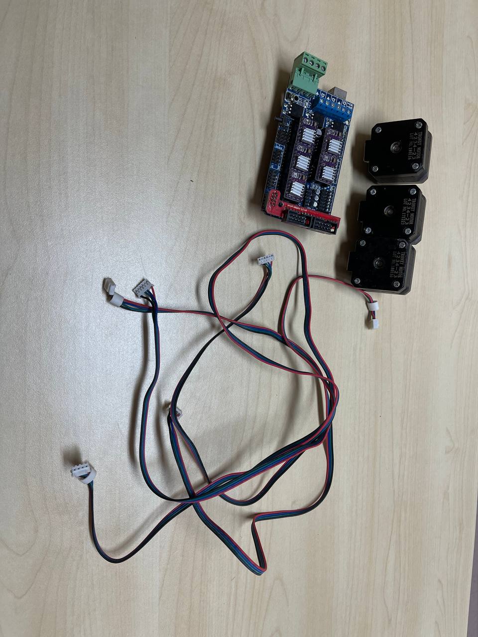
I started my final project quite late. Determined to graduate, I pulled out my trump card, exhausting my personal inventory. I happen to have some NEMA17 laying around from a decomissioned 3D printer (to be exact, it is an Anet A8 clone, a TronXY P802EA). Reason I decomissioned it was that I have used it pretty well for around 2-3 years. I don’t print every day, but definitely used weekly (except when it breaks down and I would spend months debugging and troubleshooting). I digress, I took the 2 Z-axis motors and the X-axis motors out as they “looked the same”. I also fitted a RAMPS1.6 to the 3D printer, as the built-in Melzi board has its stepper drivers burnt out (that’s a story for another day).
Exploring the stepper driver

I had some idea that I needed to supply pulses of 50% duty cycle of various periods to achieve different speeds on the stepper motor, and another pin to set the direction of the stepper. But that is about it.
I then looked up a tutorial on how to use the DRV8825 to drive a stepper. Before using the stepper, we need to understand what do the pins do
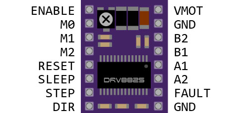
| Pin Name | Description |
|---|---|
| EN | Pull to low to enable the driver |
| M0, M1, M2 | Use these to set the microstepping |
| RST | Resets internal clock of stepper when pulled to low |
| SLP | Sets the stepper to a low powered mode |
| STEP | receive 50% duty cycle pulses of various periods to modify speed of stepper |
| DIR | HIGH -> clockwise; LOW -> counter-clockwise |
| VMOT | Stepper input supply (positive) |
| GND MOT | Stepper input supply (negative) |
| B2, B1, A2, A1 | Output to stepper coils |
| FAULT | When pulled to Low, indicates over-current protection triggered |
| GND LOGIC | Ground of logic (from microcontroller). To be pulled to same level with GND VMOT |
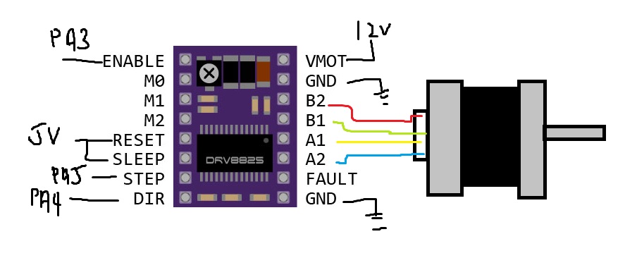
Using the stepper
The following is the wiring diagram of the stepper driver to the microcontroller and stepper motor (taken directly from lastminuteengineer website).
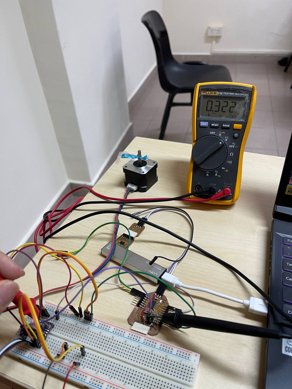
The circuit is implemented on a breadboard to quickly test its functionality
As a test, to supply \(12V\), I used a power adapter I had laying around that supplied roughly \(12.27V\) as measured with an Ampmeter.
To maximize the speed of the motor, I went with setting the motor to operate at fullstep. This is done by leaving the connections open at
After that, I wrote a piece of code to test the stepper
#define EN 10   //PA3
#define STEP 1 // PA5
#define DIR 0  // PA4

#define MICROSTEP 1 // microstepping mode

void setup() {
  // put your setup code here, to run once:
  pinMode(EN, OUTPUT);
  pinMode(STEP, OUTPUT);
  pinMode(DIR, OUTPUT);
  digitalWrite(EN, LOW);
}

void loop() {
  // put your main code here, to run repeatedly:
  digitalWrite(DIR, HIGH); // set to rotate clockwise

  for(int i = 0; i < 200 * MICROSTEP; i++) {
    digitalWrite(STEP, HIGH);
    delayMicroseconds(500);
    digitalWrite(STEP, LOW);
    delayMicroseconds(500);
  }
  delay(1000);

  digitalWrite(DIR, LOW);
  for(int i = 0; i < 200 * MICROSTEP; i++) {
    digitalWrite(STEP, HIGH);
    delayMicroseconds(500);
    digitalWrite(STEP, LOW);
    delayMicroseconds(500);
  }
  delay(1000);
}
Here, I face my first problem, when I try to set the delayMicroseconds command to be around 500, it vibrates in place. After reading on some articles, I found out that it could be the an issue with the DRV8825 limiting the current. To solve this, we need to calibrate the value.
Calibrating stepper
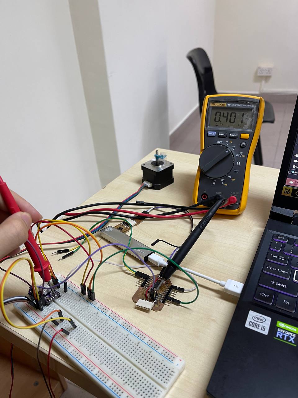
I read up ways to calibrate the driver. This is done by rotating the potentiometer on the driver and checking the potentiometer’s reference voltage against the ground of the motor when it is in holding position.
- Clockwise: increase
- Counter-clockwise: decrease
To set the motor to holding position, I will need to pull the stepper’s STEP and DIR to Logic HIGH.
However, the range of the “ballpark figures” are very confusing.
This site mentions the following formula
based on conventional Anet steppers, these would be around \(0.9A\), meaning the V_{ref} is roughly \(0.45\). However, I was afraid that would break the stepper motor itself, so I have set the value to be around 90% of the value state, which is around.
However, based on all3Dp’s website, they have a vastly different way of calculating
This is the absolute maximum of what the motor can handle (?). The value of R_sense is \(0.5{\Omega}\)
If we follow by the first eqn, the value we get is \(0.405A\), while the latter is \(3.24{\Omega}\). Which one is correct?
For now, I am setting it to be around \(0.405A\). If there is a need for my robot to move faster, I will increase the \(V_{ref}\) value accordingly.
Update: Based on Steven’s recommendation, I should read the datasheet before refering to any tutorials online.
Update 2: Based on physically looking at the stepper motor’s size, it seems to be a regular NEMA17 (not long, nor short). Therefore, we can estimate the current draw to be about \(1.2 - 1.5A\).
Result of testing
CAD
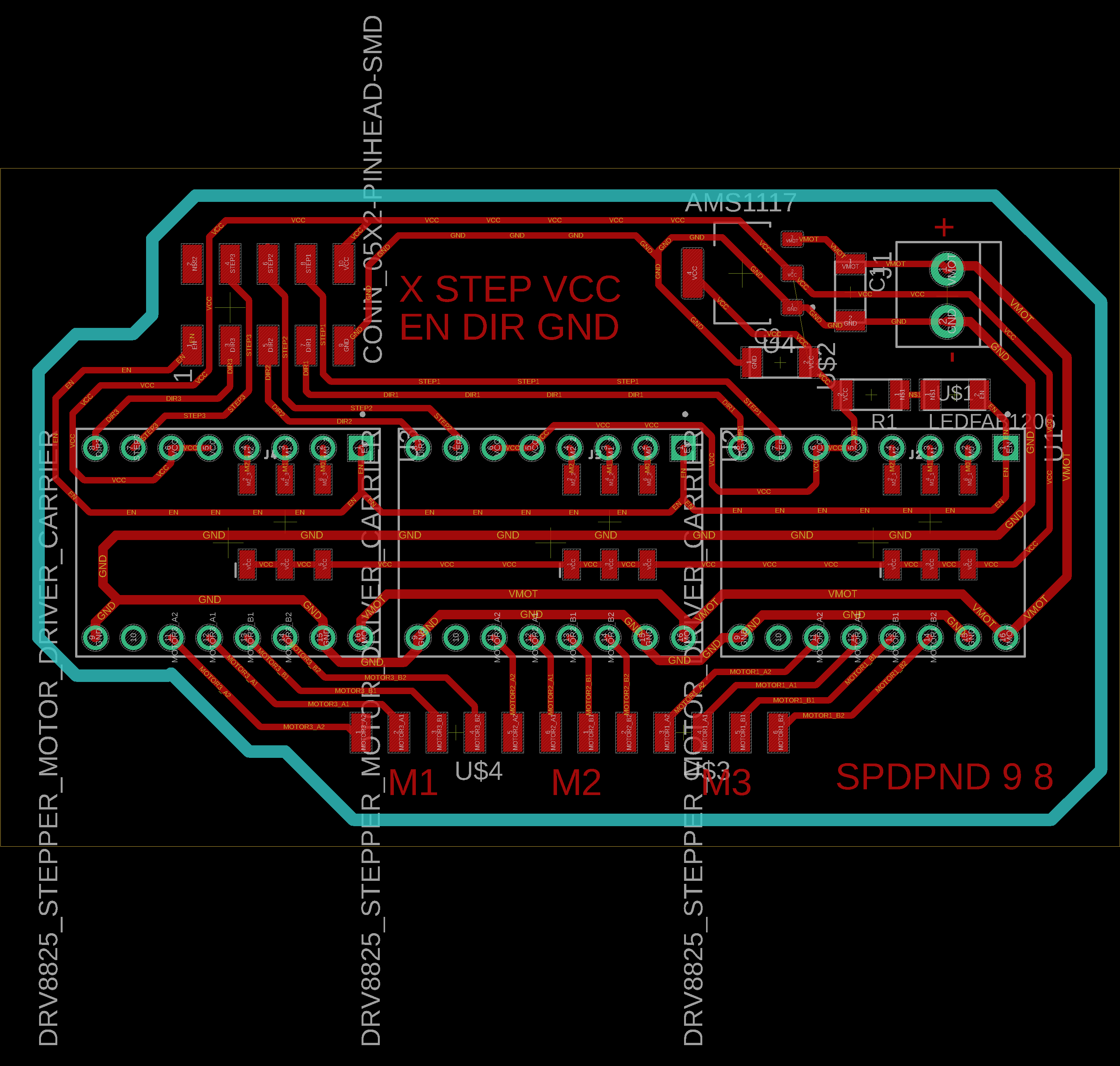
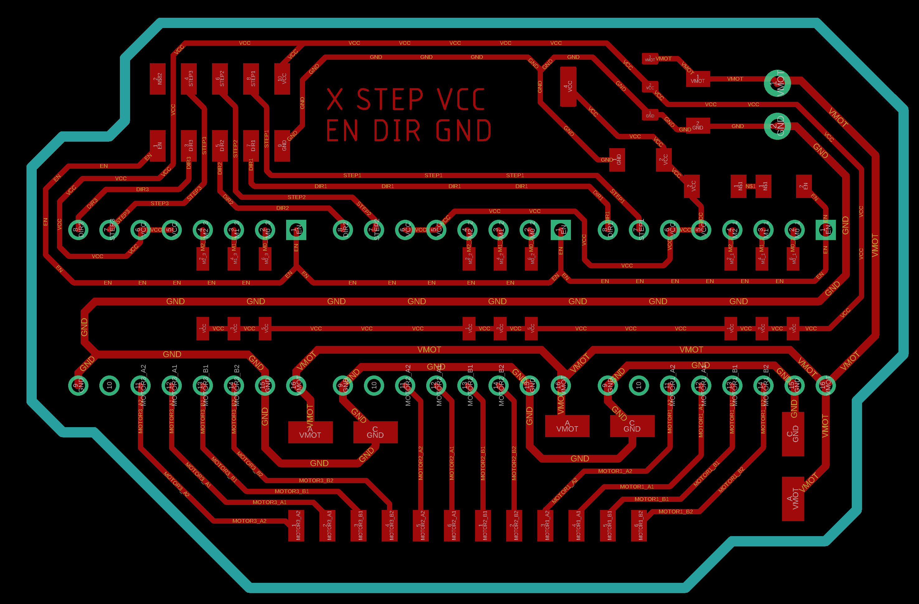
With these knowledge in mind, I made a driver board to house the DRV8825s.
Circuit is as shown
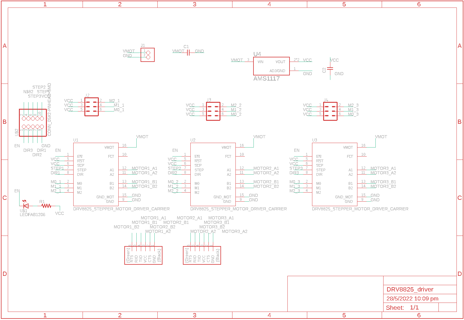
Download DRV8825 driver here: (https://www.snapeda.com/parts/DRV8825%20STEPPER%20MOTOR%20DRIVER%20CARRIER/Pololu/view-part/?welcome=home)
After pondering a few designs, this was the one I came up with that fits the (roughly) 75mm * 50mm FR1 board.
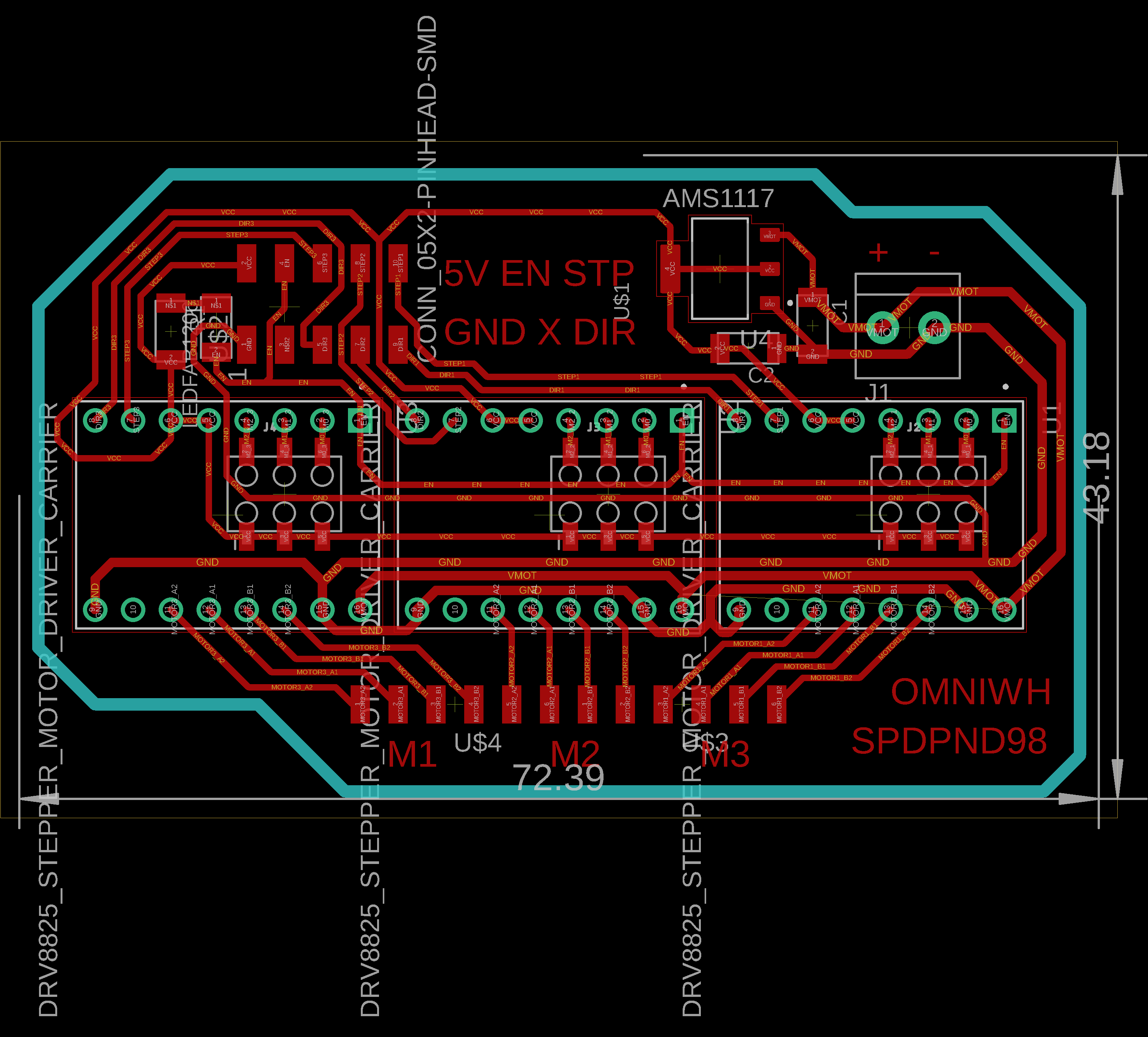
Although I pass DRC, some parts do have have enough clearance for a 16mil drill bit to generate a path.
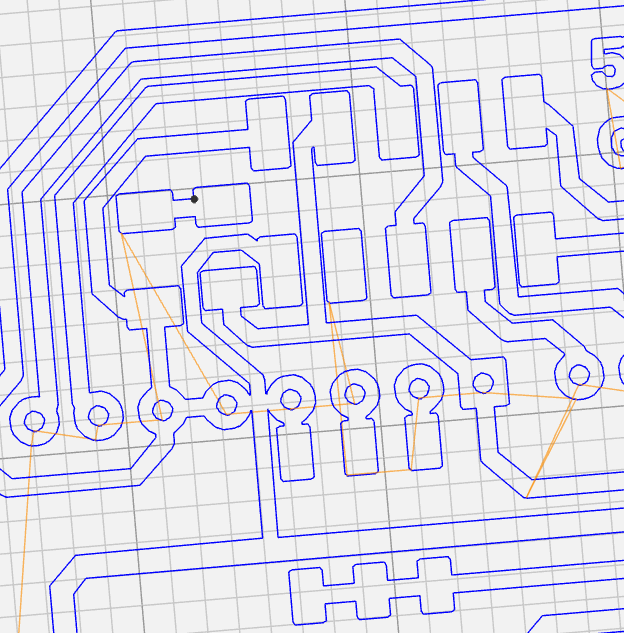
Ironically, this led me to a rabbit hole of fixing the paths. I spent hours on fixing it with no avail. I finally settled on a design with no path generation issues
A neat trick I learnt was adjusting the “pairity” of the wires. Essentially, sometimes the wires would criss-cross to reach their destinations. This can be achieved by swapping the order of wire around a pin’s pad.
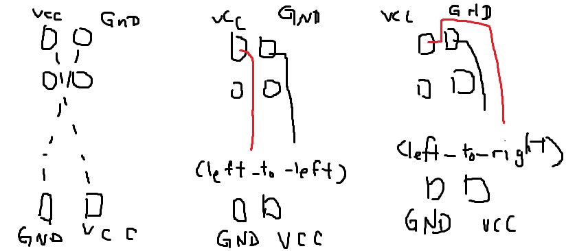
So sometimes, if there is a “cris-cross” required, we can check whether we can chain a change of parity to be able to route the wire.
Idea: Can we have 2-3 boards instead of one?
Where this idea came about is that because we are using V-bits, it can get tricky to properly level the bed. Furthermore, should my circuit have any issues, I would need to redesign the entire board and remill (which would take a few days altogether…). Perhaps a better way is to abstract the board in several logical segments and mill and test them separately
Initially, my idea is as follows:
- Stepper 1
- Stepper 2
- Stepper 3
- Power system + microcontroller
I asked my instructor, Steven, whether this design makes sense. He suggested I have power and 1 stepper driver on one board, then design another board with 2 steppers; that would also make design sense.
Another suggestion Steven gave was to use flat endmills, which would ease my concern. If my board works as is, then I wouldn’t need to spend time redesigning the board(s).
After thinking about it throughout the weekends, I figured that I would give the flatend mill a try first. If my board doesn’t work then I will pursue this idea.
Milling
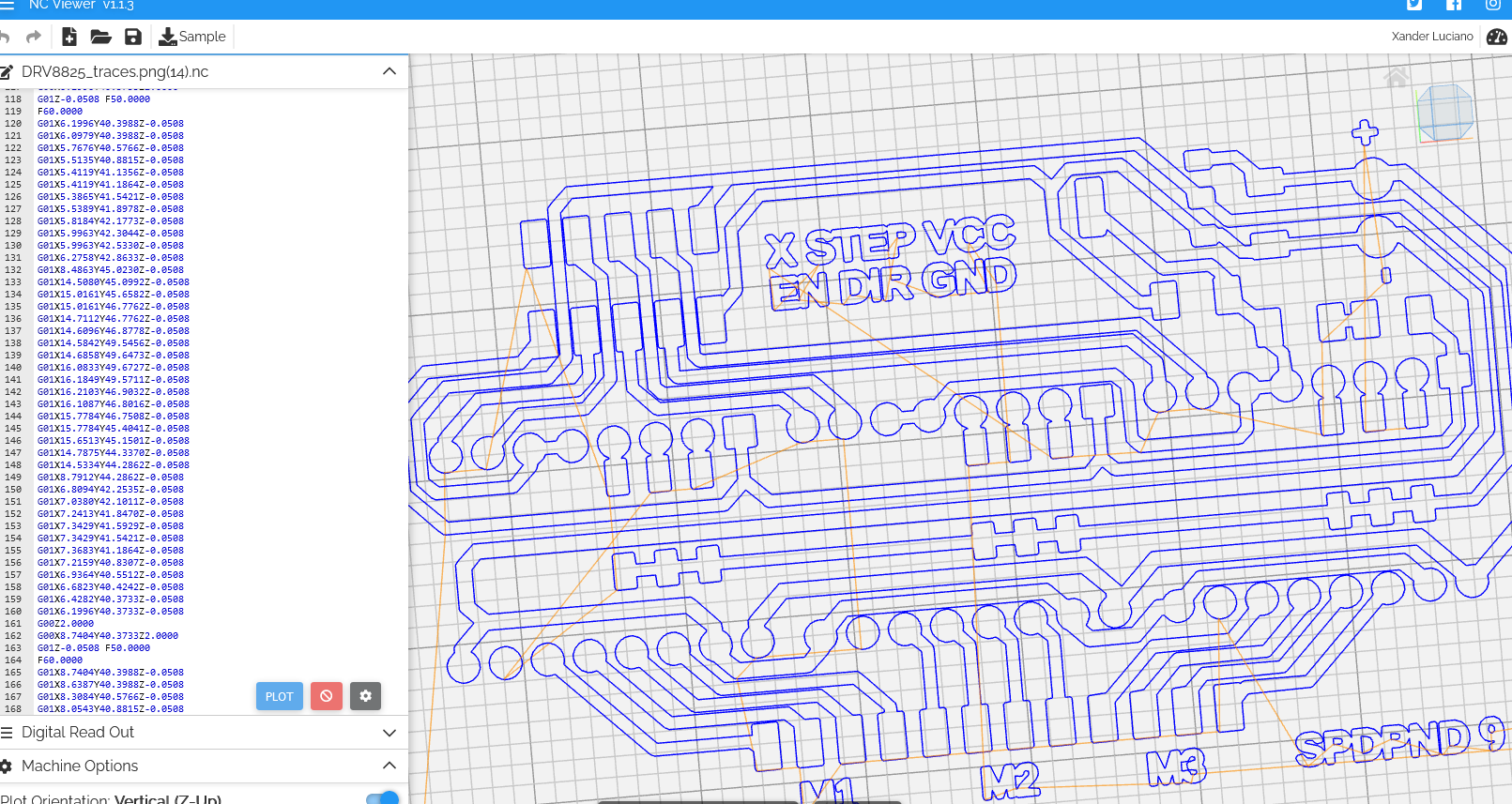
I milled the board with similar settings as what I have for other boards. G Code generated from Mods.
Traces
Tool: 0.4mm Flat endmill
| Description | Setting |
|---|---|
| tool diameter | 0.37mm |
| cut depth | 0.05mm |
| max depth | 0.05mm |
| offset number | 1 |
Outline
Tool: 0.8mm Flat endmill
| Description | Setting |
|---|---|
| tool diameter | 0.78 |
| cut depth | 0.35mm |
| max depth | 1.68mm |
| offset number | 1 |
Here is the result:

Notice that the board seems to have been cut-off near the right side of the edge. Actually, the line conincides with the board border, as the milling tool actually did shave off some material from the edge.
Update: After Steven has taken a look at my board, he recommended to use Eagle to generate the paths. This is because the drill holes seem to be too big, and eagle will likely be able to handle it from design file, instead of using mods to try and fit the size of the hole.
| Settings | value |
|---|---|
These are some comparison with the current board
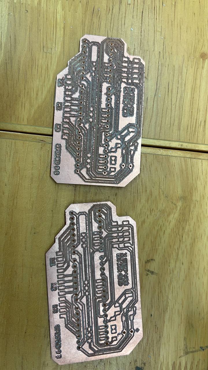
At first glance, it seems that my board looks a lot better. However, paying close attention to the drill holes on my board, the copper traces are practically non-existent. This would potentially cause problems, and I am grateful to Steven for pointing that out.
I went on and soldered some components and here is my result
This is a video of my testing
Finally, I changed the lead terminals to be thicker wires to carry current from a power source. An idea later popped up in my mind to use barrel jack, and temporarily connect a 12V supply to the robot. This can temporarily be on the sonar holes for integration (since I won’t be using those holes for now)
Oopsies: Did not check what was required for DRV8825
After Steven mentioned a \(100{\mu}F\) required for DRV8825, I immediately picked up my RAMPS1.6 to check, and sure enough, there is a capacitor of that size on the board as well.
This is a problem: if the robot uses a lot of current, the driver may blow up due to current spikes. I have to hotfix that, or remill a board for that
Could I potentially put a \(300{\mu}F\) capacitor instead at the input voltage side?
Regardless, I redesigned the board and fit in \(100{\mu}F\) at each VMOT and GND in case I have the time to mill and test it again.
Testing the stepper drivers
Next, I calibrated each stepper motor driver. I noticed that at \(0.4A\), the wheels might not be able to rotate at \(500{\mu}s\). Therefore, I set the reference voltage to be at \(0.57V\), so the curent limit becomes roughly \(1.2A\), which should be ok for this stepper. }, I hooked up the stepper motors to ensure the PCB works.
Thinking how to make it run
After ensuring it works with the same test code I’ve written above (except with more pins turning on/off), I went on and explored one of the ways to drive the stepper motors.
The issue, which I have noticed, was that I was driving each stepper individually and is blocking. I needed a pseudo parallel code. A quick google search led me to Speedy Stepper, which was optimized for speed.
I ran a few example programs, before finally somewhat settling down on the method of controlling the steppers:
#define EN 0   //PA4

#define DIR_1 3  // PA7
#define STEP_1 8 // PA1

#define DIR_2 2  // PA6
#define STEP_2 9 // PA2

#define DIR_3 1  // PA5
#define STEP_3 10 // PA3

#define MICROSTEP 1 // microstepping mode

#include <SpeedyStepper.h>

// idea to control: use a global timer and write a speed manager for each motor. -> use SpeedyStepper library, code refered to example 6

SpeedyStepper stepperRight;
SpeedyStepper stepperLeft;
SpeedyStepper stepperFront;


void setup() {
  // put your setup code here, to run once:
  pinMode(EN, OUTPUT);

  // setup steppers
  stepperRight.connectToPins(STEP_1, DIR_1);
  stepperLeft.connectToPins(STEP_3, DIR_3);
  stepperFront.connectToPins(STEP_2, DIR_2);

  digitalWrite(EN, LOW);
}

void loop() {
  // put your main code here, to run repeatedly:

  //This should prep it to rotate 1 second
  stepperRight.setSpeedInStepsPerSecond(1000); // 5 RPS
  stepperRight.setAccelerationInStepsPerSecondPerSecond(1000);
  stepperRight.setupRelativeMoveInSteps(-1000);

  stepperLeft.setSpeedInStepsPerSecond(1000); // 5 RPS
  stepperLeft.setAccelerationInStepsPerSecondPerSecond(1000);
  stepperLeft.setupRelativeMoveInSteps(1000);

  while((!stepperRight.motionComplete()) || (!stepperLeft.motionComplete())) {
    // add fast code here
    stepperRight.processMovement();
    stepperLeft.processMovement();
  }

  delay(1000);
}
The motor rotates as per expected. It has a very nice feature of accelerating and decelerating as well.
The drivers are powered by a 12V 7A Li-ion battery charger. If time does not permit, I might stick to this just to be on the safe side. I am still paranoid of shorting stuff.