10. Output Devices
This week I learned about Output Devices.
10.0 Assignment of this week
10.0.1 Individual assignment
Add an output device to a microcontroller board you’ve designed, and program it to do something
10.0.2 Group assignment
Measure the power consumption of an output device
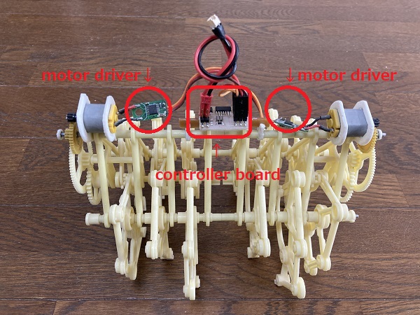
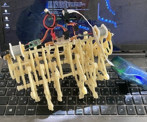
10.1 The object I built this week
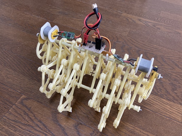
I built a ‘programmable walking robot’, with a small ATtiny44 board ‘embedded’.
10.2 Design
Mechanical components of the robot came from ‘Mini Strandbeest’, a miniaturized version of the famous ‘Strandbeest’ created by Theo Jansen.

:An image from ‘Theo Jansen’s Mini Strandbeest’ by Gakken Plus Co.,Ltd. January 14, 2011
Original Mini Strandbeest was designed to be wind-driven like its bigger brothers, I removed the wind fan and added a couple of electric motors w/gears.
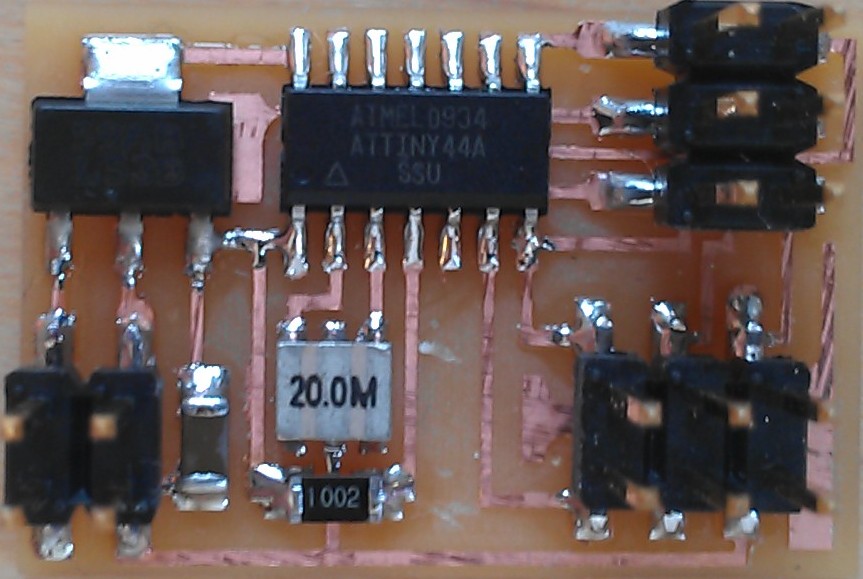
10.3 Controller board
At first, I used ATtiny44 with ‘Hello Servo 44.1’ as it was.
CAD process:
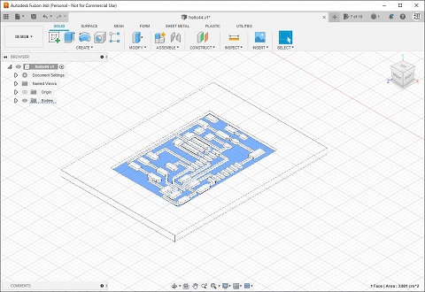
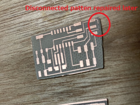
Miling and soldering process:
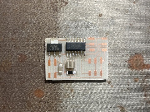
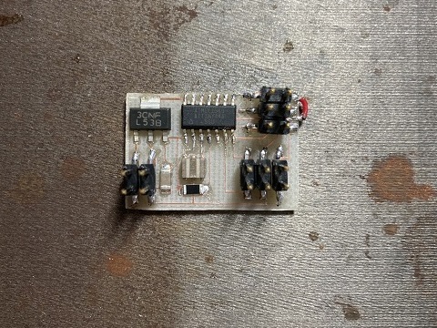
Later I added a couple of chip LEDs as power indicators. The LEDs share the same PWM outputs with the motors.
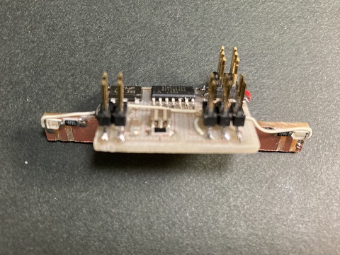
The bar under the board was hand-cutted from an excess copper clad laminate and attached to the board afterward. It acts as a LED holder and a snap-on joint to the robot body.
Parts list:
1 ATTiny44 microcontroller
1 Capacitor 22uF
1 Crystal 20MHz
1 5V regulator
Two 6 pin header
one 4 pin header
1 Red LED
1 Green LED
2 Resistor 499 ohm
Trace:
hello.servo.44.1.traces.png
Step file:
hello.servo.44.1.step
STL data for CNC:
hello.servo.44.1.stl
10.4 Motor driver boards
The PWM outputs from ATtiny44 can’t drive motors directly because of current limitation, so I added a couple of motor driver boards between the control board and motors.
The motor driver boards came from small servo motors(continuous rotation type). The boards amplify the PWM signals from the controller board to sufficient current to power the motors. They also change the direction of current according to PWM duty cycle.
10.5 Programming the motions
At first, I used hello.servo.44.2.c as it was.
HEX File:
hello.servo.44.2.hex
Movies:
10.6 Re-programming the different motions
As I wanted to add backward motions to the robot, I checked the program code and slightly modified.
It seemed that the motor driver board would reverse the direction of current if PWM duty cycle was smaller than 1/20, so I wrote additional codes according to the table below:
| Moving direction of the robot |
Time duration | PWM duty cycle for Motor L(PA6) |
PWM duty cycle for Motor R(PA7) |
| Backward | 5 sec | 1 / 80 0.25 / 20 msec |
1 / 80 0.25 / 20 msec |
| Forward | 5 sec | 1 / 13.3 1.5 / 20 msec |
1 / 13.3 1.5 / 20 msec |
| Spin turn | 10 sec | 1 / 13.3 1.5 / 20 msec |
1 / 80 0.25 / 20 msec |
| Spin turn(reverse) | 10 sec | 1 / 80 0.25 / 20 msec |
1 / 13.3 1.5 / 20 msec |
C code(modified part only):
while (1) {
      //
      // Backward motion
      //
      for (i = 0; i < loop_count; ++i) {
         set(PWM_port,PWM_pin_0);
         set(PWM_port,PWM_pin_1);
         _delay_us(250);
         clear(PWM_port,PWM_pin_0);
         clear(PWM_port,PWM_pin_1);
         _delay_us(19750);
         }
      //
      // Forward motion
      //
      for (i = 0; i < loop_count; ++i) {
         set(PWM_port,PWM_pin_0);
         set(PWM_port,PWM_pin_1);
         _delay_us(1500);
         clear(PWM_port,PWM_pin_0);
         clear(PWM_port,PWM_pin_1);
         _delay_us(18500);
         }
      //
      // Spin turn
      //
      for (i = 0; i < loop_count; ++i) {
         set(PWM_port,PWM_pin_0);
         _delay_us(1500);
         clear(PWM_port,PWM_pin_0);
         _delay_us(18500);
         set(PWM_port,PWM_pin_1);
         _delay_us(250);
         clear(PWM_port,PWM_pin_1);
         _delay_us(19750);
         }
      //
      // Spin turn(reverse)
      //
      for (i = 0; i < loop_count; ++i) {
         set(PWM_port,PWM_pin_0);
         _delay_us(250);
         clear(PWM_port,PWM_pin_0);
         _delay_us(19750);
         set(PWM_port,PWM_pin_1);
         _delay_us(1500);
         clear(PWM_port,PWM_pin_1);
         _delay_us(18500);
         }

    }
Files:
hello.servo.44.3.c
makefile
hello.servo.44.3.hex
Program is written into the board. The robot is capable of on-board programming…
Movie:
10.7 Power consumption(as group assignment)
There were not any equipments which could directly measure current value in our lab, so I calculated the value from the measured values of resistance and voltage according Ohm’s law.
Measured resistance of one motor: 5 Ohm ( 2.5 Ohm / paralleled pair)
Measured voltage of the device at working: 1.6 V - 2.6 V
Calculated current value: 0.64 A - 1.04 A ( 0.32 A - 0.52 A per one motor) (formula: I = V/R)
Manufacturer’s specications of the motor:
Model: Mabuchi FF-030PK-11160
| OPERATING RANGE | CURRENT (NO LOAD) |
CURRENT (MAX. EFFICIENCY) |
CURRENT (STALL) |
| 2.0 - 5.5 V | 0.066 A | 0.25 A | 0.91 A |
10.8 Conclusion
I enjoyed the assignment of this week very much.
I learned very basic skills of AVR programming by C, especially about a servo motor control method using ‘soft PWM’.