14. Networking and communications
Instruction
individual assignment:
- design, build, and connect wired or wireless node(s)with network or bus addresses → In this page
group assignment:
- send a message between two projects → Here
What I did in this week
- Test board by serial connection → Group Assignment
- Running servo motors from my smartphone (between 2 projects) → Group Assignment
- network1 : Design and Connect wireless node by using OLED Display → in this page
- network2 : Design and Connect wireless node by using MP3 Sound Module → in this page
Network1 : Design and Connect wireless node by using OLED Display
Device I used :
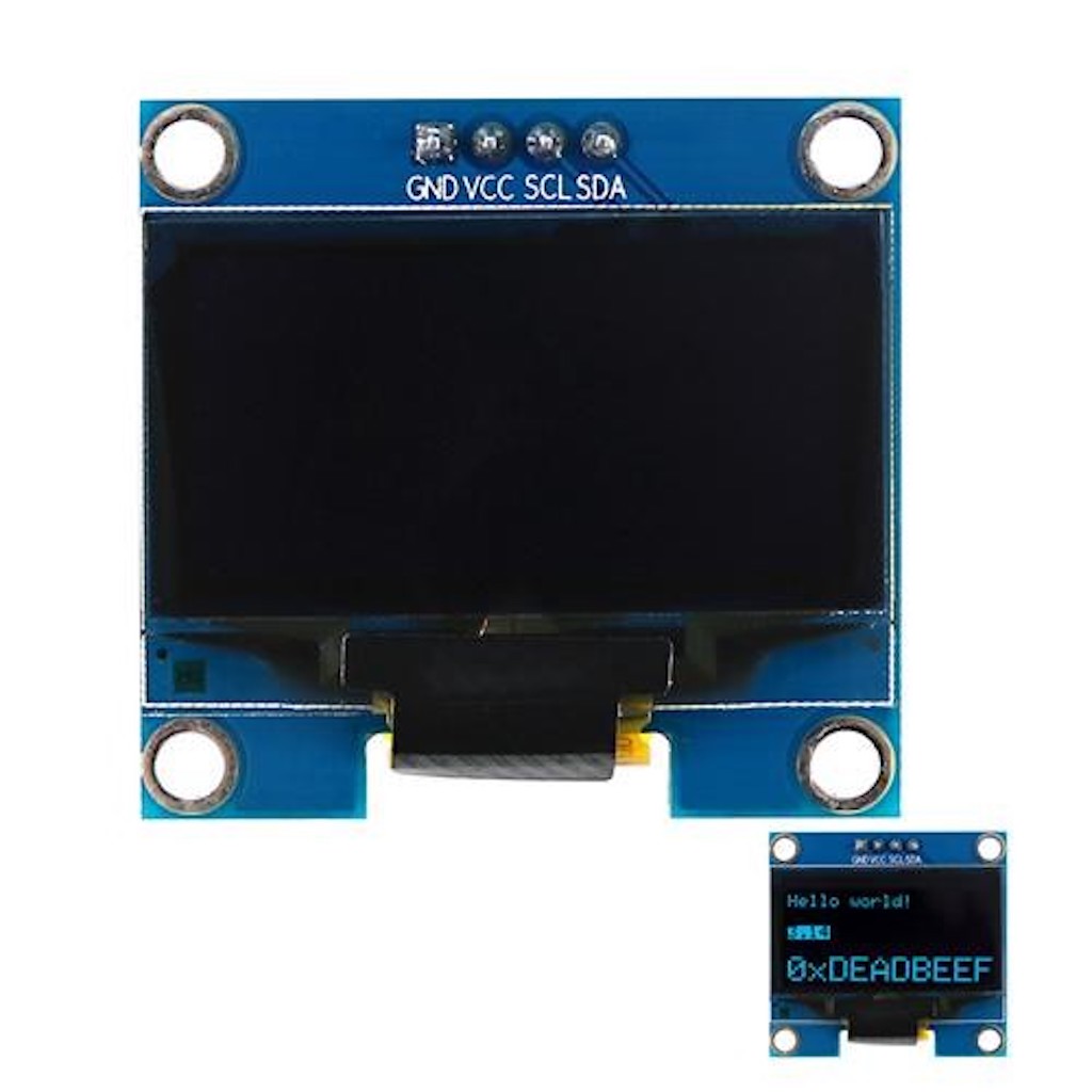
0.96 Inch 128x64 i2c White OLED Module Display
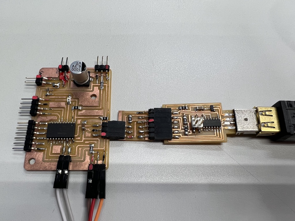
The circuit-board for final project made in Week11
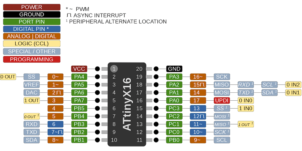
ATtiny3216
used SCL(1) and SDA(1) in 18 and 17 pin
(Note : So need to swap)
Schematic

Find address by i2c_scanner
Code
Scan the address of the oled that is secondary
#include <Wire.h>

void setup() {
   Serial.begin(115200);
   Wire.begin();
   }

uint8_t address,count;

void loop() {
   count = 0;
   Serial.println("start scan ...");
   for (address = 1; address < 127; address++) {
      Wire.beginTransmission (address);
      if (Wire.endTransmission () == 0) {
         count += 1;
         Serial.print("   found ");
         Serial.print(address,DEC);
         Serial.print(" (0x");
         Serial.print(address,HEX);
         Serial.println (")");
         }
      }
   if (count == 0)
      Serial.println("   no devices found");
   delay(1000);
   }
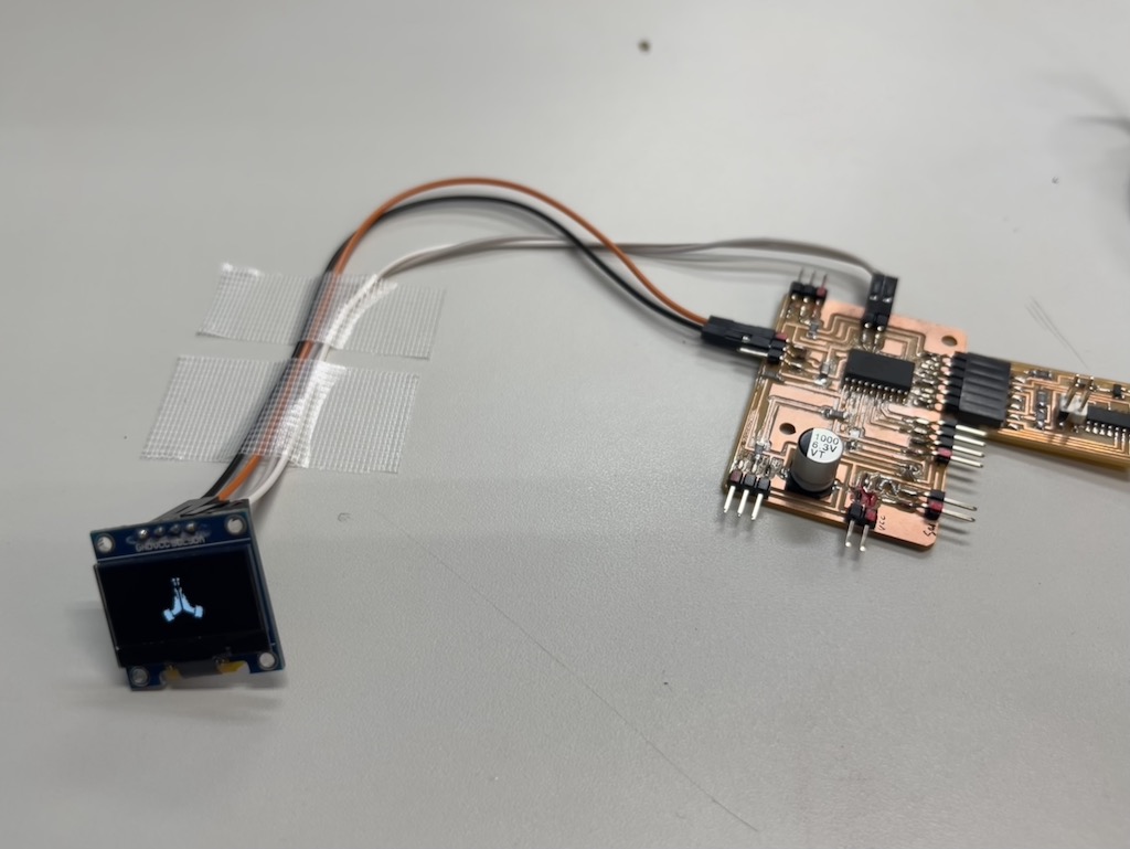
Build
Connect OLED to the board
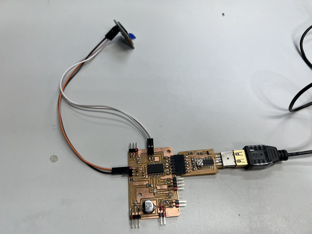
check serial board
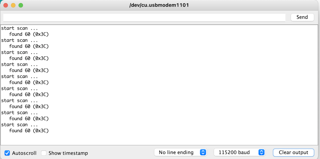
It turned out that address is 0x3C
OLED Program from Arduino IDE
Install library
- SSD1306 library
- GFX library
- Adafruit BusIO including
Write sketch
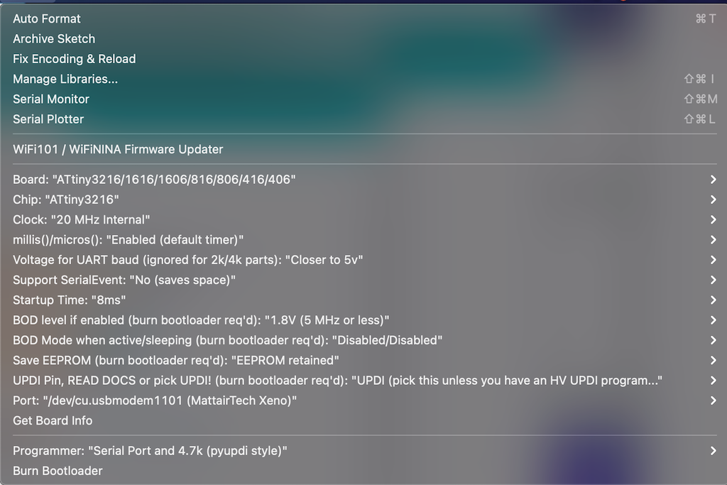
Arduino Sample
Example -> Adafruit SSD1306 -> ssd1306_128x64_i2c
Arrangement
- Change address
0x3C - add
Wire.swap(1)
Code arranged
i2c arranged code is i2c arranged.ino
/Users/yukiyayamane/repos/yamane2/docs/files/week14/code_of_display_shrine.ino
Display original image
- Image to CPP
- set
- canvas size : 64 x 64
-
brightness shrethold 250
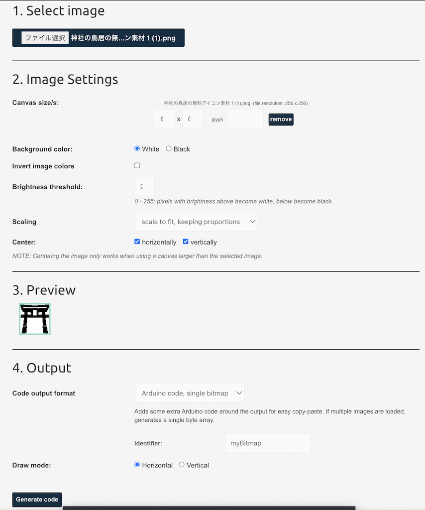
Generate Code
const unsigned char myBitmap [] PROGMEM = {
    // shrine, 64x64px
    0x00, 0x7f, 0xff, 0xff, 0xff, 0xff, 0xfe, 0x00, 0x00, 0x00, 0x00, 0x7f, 0xfe, 0x00, 0x00, 0x00,
    0x00, 0x00, 0x00, 0x00, 0x00, 0x00, 0x00, 0x00, 0x00, 0x00, 0x00, 0x00, 0x00, 0x00, 0x00, 0x00,
    0x80, 0x00, 0x00, 0x00, 0x00, 0x00, 0x00, 0x01, 0x83, 0xf8, 0x00, 0x00, 0x00, 0x00, 0x1f, 0xc1,
    0x83, 0xff, 0xff, 0xff, 0xff, 0xff, 0xff, 0xc1, 0x80, 0xff, 0xff, 0xff, 0xff, 0xff, 0xff, 0x01,
    0xc0, 0x00, 0x01, 0x00, 0x00, 0x80, 0x00, 0x03, 0xc0, 0x00, 0x00, 0x00, 0x00, 0x00, 0x00, 0x03,
    0xc0, 0x00, 0x00, 0x00, 0x00, 0x00, 0x00, 0x03, 0xe0, 0x00, 0x00, 0x00, 0x00, 0x00, 0x00, 0x07,
    0xf0, 0x00, 0x00, 0x0f, 0xf0, 0x00, 0x00, 0x0f, 0xf0, 0x00, 0x00, 0x0f, 0xf0, 0x00, 0x00, 0x0f,
    0xf8, 0x00, 0x00, 0x0f, 0xf0, 0x00, 0x00, 0x1f, 0xf8, 0x00, 0x00, 0x0f, 0xf0, 0x00, 0x00, 0x1f,
    0xff, 0x00, 0x00, 0x0f, 0xf0, 0x00, 0x00, 0xff, 0xff, 0x80, 0xfc, 0x0f, 0xf0, 0x3f, 0x01, 0xff,
    0xff, 0x80, 0xff, 0x0f, 0xf0, 0xff, 0x01, 0xff, 0xff, 0x80, 0xff, 0x0f, 0xf0, 0xff, 0x01, 0xff,
    0xff, 0x80, 0xff, 0x0f, 0xf0, 0xff, 0x01, 0xff, 0xff, 0x80, 0xff, 0x0f, 0xf0, 0xff, 0x01, 0xff,
    0x80, 0x00, 0x00, 0x0f, 0xf0, 0x00, 0x00, 0x01, 0x80, 0x00, 0x00, 0x0f, 0xf0, 0x00, 0x00, 0x01,
    0x80, 0x00, 0x00, 0x00, 0x00, 0x00, 0x00, 0x01, 0x80, 0x00, 0x00, 0x00, 0x00, 0x00, 0x00, 0x01,
    0x80, 0x00, 0x00, 0x00, 0x00, 0x00, 0x00, 0x01, 0x00, 0x00, 0x00, 0x00, 0x00, 0x00, 0x00, 0x01,
    0x00, 0x00, 0x00, 0x00, 0x00, 0x00, 0x00, 0x00, 0xff, 0x01, 0xff, 0xff, 0xff, 0xff, 0x80, 0xff,
    0xff, 0x01, 0xff, 0xff, 0xff, 0xff, 0x80, 0xff, 0xff, 0x01, 0xff, 0xff, 0xff, 0xff, 0x80, 0xff,
    0xff, 0x01, 0xff, 0xff, 0xff, 0xff, 0x80, 0xff, 0xff, 0x01, 0xff, 0xff, 0xff, 0xff, 0x80, 0xff,
    0xff, 0x01, 0xff, 0xff, 0xff, 0xff, 0x80, 0xff, 0xfe, 0x01, 0xff, 0xff, 0xff, 0xff, 0x80, 0x7f,
    0xfe, 0x01, 0xff, 0xff, 0xff, 0xff, 0x80, 0x7f, 0xfe, 0x01, 0xff, 0xff, 0xff, 0xff, 0x80, 0x7f,
    0xfe, 0x01, 0xff, 0xff, 0xff, 0xff, 0x80, 0x7f, 0xfe, 0x01, 0xff, 0xff, 0xff, 0xff, 0x80, 0x7f,
    0xfe, 0x03, 0xff, 0xff, 0xff, 0xff, 0xc0, 0x7f, 0xfe, 0x03, 0xff, 0xff, 0xff, 0xff, 0xc0, 0x7f,
    0xfe, 0x03, 0xff, 0xff, 0xff, 0xff, 0xc0, 0x7f, 0xfe, 0x03, 0xff, 0xff, 0xff, 0xff, 0xc0, 0x7f,
    0xfc, 0x03, 0xff, 0xff, 0xff, 0xff, 0xc0, 0x3f, 0xfc, 0x03, 0xff, 0xff, 0xff, 0xff, 0xc0, 0x3f,
    0xfc, 0x03, 0xff, 0xff, 0xff, 0xff, 0xc0, 0x3f, 0xff, 0xff, 0xff, 0xff, 0xff, 0xff, 0xff, 0xff,
    0xfc, 0x01, 0xff, 0xff, 0xff, 0xff, 0x80, 0x3f, 0xf8, 0x01, 0xff, 0xff, 0xff, 0xff, 0x80, 0x1f,
    0xf8, 0x01, 0xff, 0xff, 0xff, 0xff, 0x80, 0x1f, 0xf8, 0x01, 0xff, 0xff, 0xff, 0xff, 0x80, 0x1f,
    0xf8, 0x03, 0xff, 0xff, 0xff, 0xff, 0xc0, 0x1f, 0xf0, 0x03, 0xff, 0xff, 0xff, 0xff, 0xc0, 0x0f,
    0xf0, 0x03, 0xff, 0xff, 0xff, 0xff, 0xc0, 0x0f, 0xf0, 0x03, 0xff, 0xff, 0xff, 0xff, 0xc0, 0x0f,
    0xf0, 0x03, 0xff, 0xff, 0xff, 0xff, 0xc0, 0x0f, 0xf0, 0x03, 0xff, 0xff, 0xff, 0xff, 0xc0, 0x0f,
    0xf0, 0x03, 0xff, 0xff, 0xff, 0xff, 0xc0, 0x0f, 0xe0, 0x03, 0xff, 0xff, 0xff, 0xff, 0xc0, 0x07,
    0xe0, 0x03, 0xff, 0xff, 0xff, 0xff, 0xc0, 0x07, 0xe0, 0x03, 0xff, 0xff, 0xff, 0xff, 0xc0, 0x07,
    0xe0, 0x07, 0xff, 0xff, 0xff, 0xff, 0xe0, 0x07, 0xe0, 0x1f, 0xff, 0xff, 0xff, 0xff, 0xf8, 0x07
};
Displayed on the OLED display
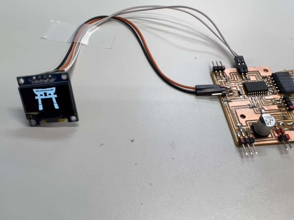
Arrange the image
code to display the icon is display shrine.ino
->success
Network2 : Design and Connect wireless node by using MP3 Sound Module
The decice I used : MP3 Voice Module
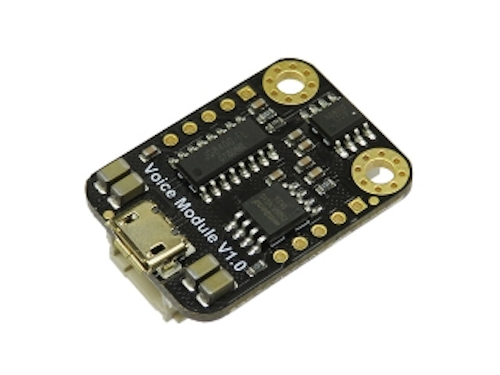
Specification
- Operating Voltage: 3.3V ~ 5V
- Interface: UART
- Support MP3 WAV Hardware Decoding
- Support Sampling Rate (KHz): 8/11.025/12/16/22.05/24/32/44.1/48
- Support to imitate SPIFLASH to U disk, and audios in SPIFLASH can be updated by the way to operate USB flash drive
- Support 30 levels of volume adjustment
- Dimension: 22x30mm/0.87x1.18in
Board Overview
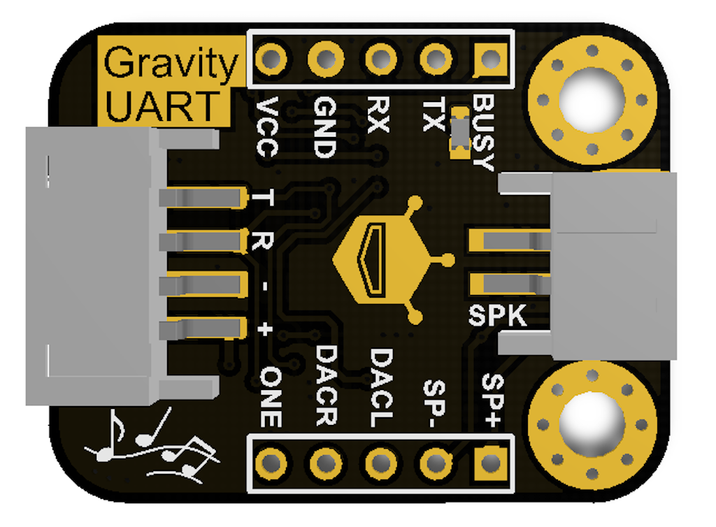
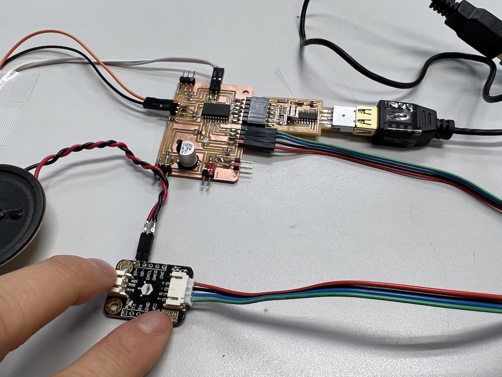
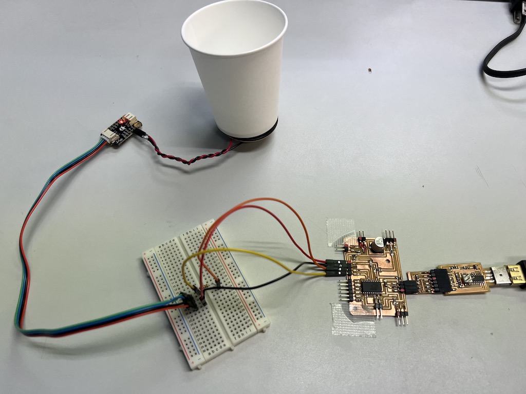
Connection
MP3 Voice Module to the board
Wired the MP3 Module and speaker to the board
Code for make sound by MP3
Use sample code from this referenced page
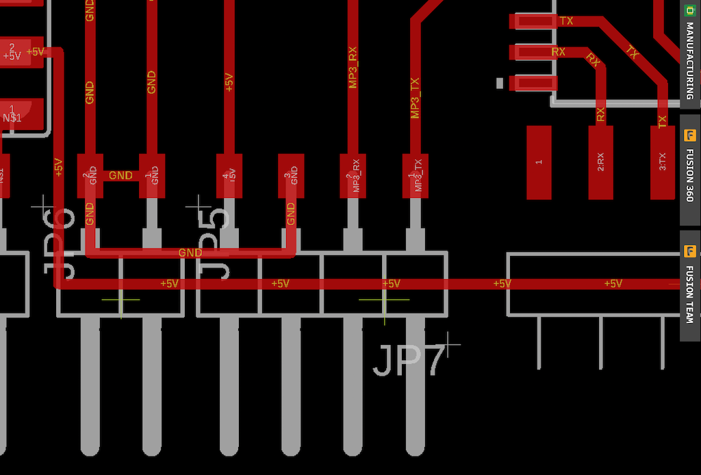
Arrange the code
- Assign RX to be TX so that TX of the module becomes RX of the board
- pin number of RX, TX = 5, 4
Note : syntax
SoftwareSerial(rxPin, txPin, inverse_logic)
Arranged code
code to play mp3 is playmp3.ino
Save MP3 file to the module directly like removable disk
set file name “03.mp3
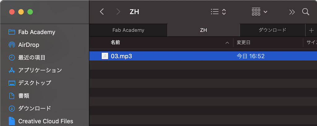
The sound could be played
However, there is a muffled noise at the beginning of playback.
So I add a 510 ohm resistor next to the speaked to try to eliminate the noise
→ I was able to eliminate the initial noise (but the playback volume is low)
→ I will try other modules at a later date.
Problem to solve for next week
- If I set delay(30000) to play sound for 30 seconds, it takes 30 seconds to play.
- How can I make it play immediately and also play in tens of seconds?
Network3 : I2C communication between 2 self-made boards (11th July Added)
Additional production was done as my global evaluator pointed out the problem.
you should implement networking protocols between 2 boards (at least one of them made and design by you), but you have to program both boards, using modules like the OLED display or the MP3 player it’s not enought for the assignment.
Using two breakout boards I had made before, I programmed the NeoPixel on the secondery board to light up through I2C communication when a button on the master board was pressed on. These boards are made by myself from scratch.
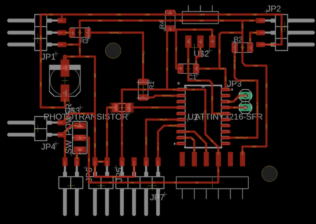
Master/Secondary Breakout boards I used
Push button on the Master board (illuminated mini LED for check) -> Illuminate NeoPixel on the Secondary board
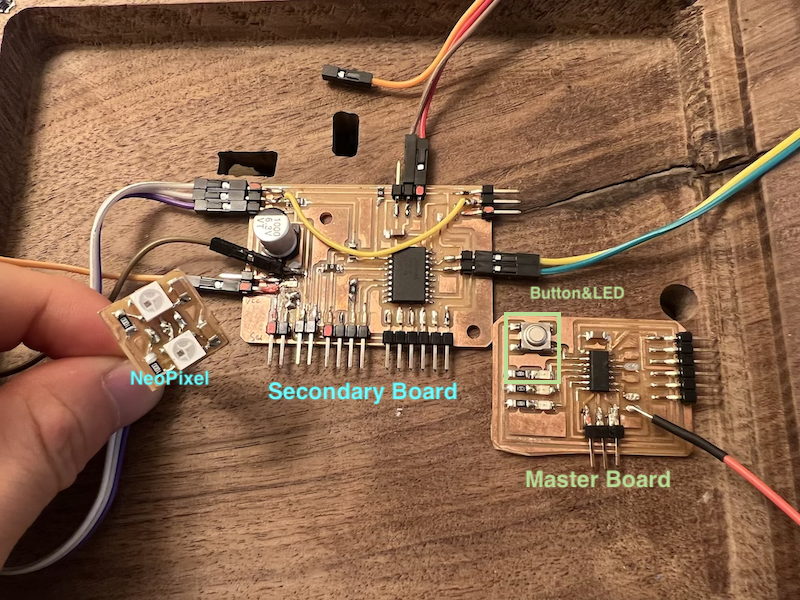
Master Board which is put the button
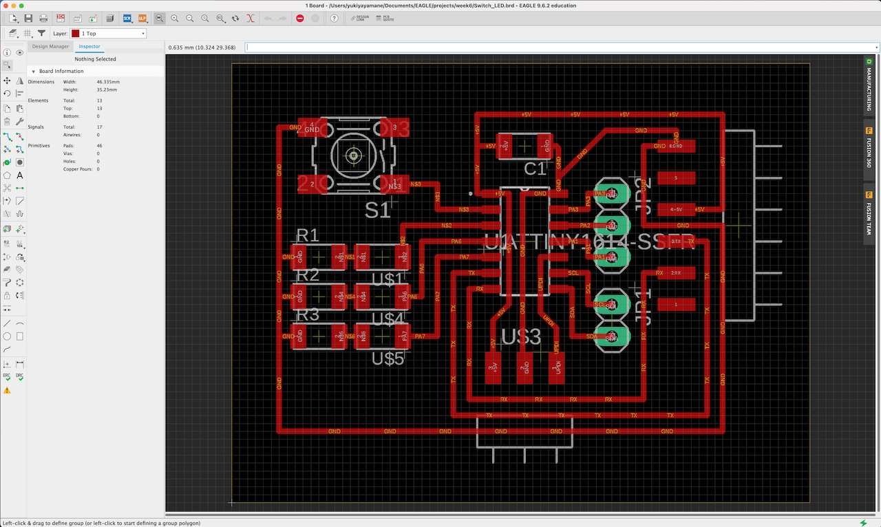
Secondary Board which is connected Neopixel
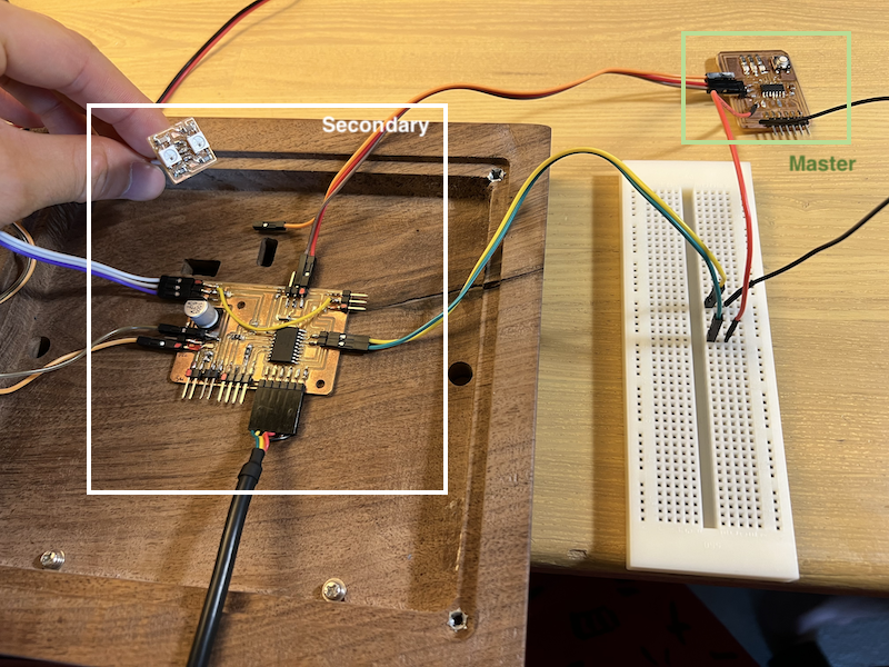
Networking
The two boards were connected via a bullet board for I2C communication.
Code
Code for Master board
#include <Wire.h>

int debug_pin = 13;
const int BUTTON = 0;
const int LED = 1;
int buttonState = 0;

void setup () {
  //Wire.swap(1);
  Serial.begin(9600);
  pinMode(BUTTON, INPUT_PULLUP);
  pinMode(LED, OUTPUT);
  digitalWrite(BUTTON, HIGH);
  delay (300);
  while (!Serial);
}

void loop () {
  buttonState = digitalRead(BUTTON);
  if (buttonState == LOW) {
    digitalWrite(LED, HIGH);
    delay (100);
    Wire.beginTransmission(0x1);
    Wire.write(1);
    Serial.println("1 sent to #1");
    Wire.endTransmission ();
  }
  else {
    digitalWrite(LED, LOW);
    Serial.write(100);
  }
}
Code for Secondary board
int feedback_pin = 0; //NeoPixel
#define NUMPIXELS 2
#include <TinyWire.h>;
#include <tinyNeoPixel.h>
byte own_address = 0x3C;
bool statepin = false ;

tinyNeoPixel pixels = tinyNeoPixel(NUMPIXELS, feedback_pin, NEO_GRB + NEO_KHZ800);

void setup () {
  Wire.swap(1);
  pinMode(feedback_pin, OUTPUT);
  digitalWrite(feedback_pin, HIGH);
  delay (300);
  TinyWire.begin (own_address);
  TinyWire.onReceive(onI2CReceive);

  // neopixel setup
  pixels.begin();
  pixels.clear(); // Set all pixel colors to 'off'

}

void loop () {

  if (statepin == true) {
    delay(1000);
    NeoFade(180);
    delay(500);
    digitalWrite(feedback_pin, HIGH);
  } else {
    digitalWrite(feedback_pin, LOW);
  }

}
void onI2CReceive (int howMany) {
  //  while (TinyWire.available() > 0) {
  //    if (TinyWire.read() == 1) {
  while (Wire.available() > 0) {
    if (Wire.read() == 1) {

      statepin = !statepin;
    }
  }
}

void NeoFade(int FadeSpeed)
{
  int fspeed;
  for (int i = 0; i < NUMPIXELS; i++) {
    pixels.setPixelColor(i, 255, 255, 200);
  } for (int j = 1; j < 255; j = j + 2)
  {
    pixels.setBrightness(j);
    pixels.show();
    delay(FadeSpeed);
  }

}
Results
When pushing the button on the Master board (illuminated mini LED for check), NeoPixel illuminates on the Secondary board via I2C Communication between 2 boards.
What I learned in this week
- I was able to connect the sound module and OLED display to the final board via networking.
- To eliminate sound noise, put a resistor next to the module. However, volume control is required.