Week4 Electronics production
Introduction
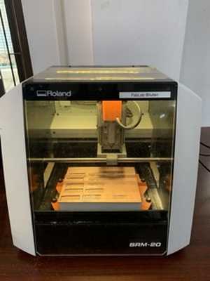
In this week, we have to characterize the specification of PCB (Printed Circuit Board) production processes and have to learn about milling machines. In our lab, we have a Roland SRM-20 machine and this machine reads an rml file. For this we need to go to Mods,which changes png format into rml.
Assignment
group assignment:
- characterize the design rules for your in-house PCB production process
- extra credit: send a PCB out to a board house
individual assignment:
- Make an in-circuit programmer that includes a microcontroller:
- extra credit: customize the design
- mill and stuff the PCB
- test it to verify that it works
- extra credit: try other PCB processes
Group assignment
The group assignment is here
ISP board
The machine: Roland SRM 20
Softwares: mods and VPanel for SRM-20
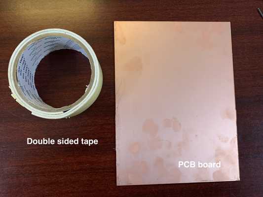
Materials required:
- PCB board- there are many types of PCB board and we will use the FR1 type.
- Double sided tape
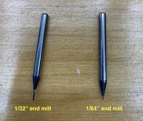
- End mills:
- 1/64”- used to mill the traces of the board
- 1/32”- used to mill the edge of the board
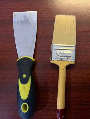
- Spatula and brush
-
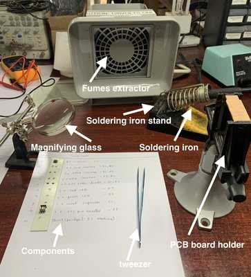
Magnifying glass
-
Fumes extractor
-
Soldering iron
-
Soldering lead
-
Stand
-
Table lamp
PCB fabrication
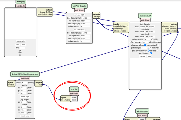
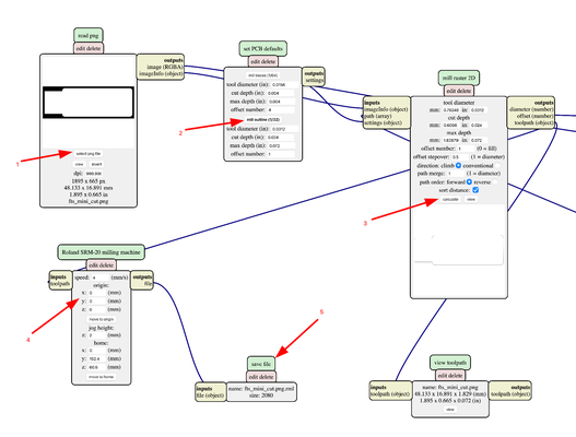
In mods
- Go to mods
- Right click-> Programs-> open server program-> Roland-mill-SRM20-PCB png
- Delete the websocket device

- To save the rml file, right click-> modules-> open server module-> file-save. (Note- the file will be saved in rml format)
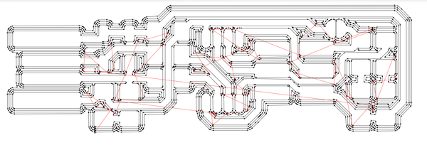
- To cut the traces (use 1/64th end mill), trace image can be found here
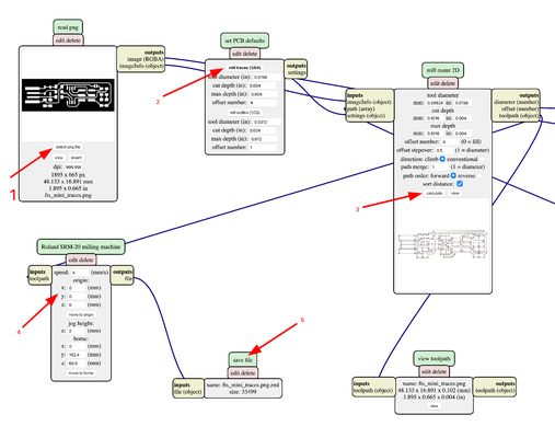
- Paths of the mill with offset 4 for the traces. The thickness of the
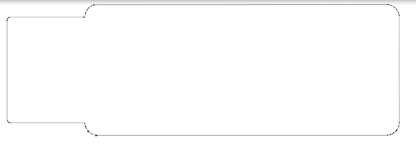
- To cut the edge (use 1/32 end mill), edge image can be found here
- Paths of the mill with offset 4 for the edge
NOTE
-
The speed or the feed rate for milling both the trace and the edge is 4mm/s. The speed should be kept low since the end-mills are very thin and fragile. The rotation speed is 8000 rpm.
-
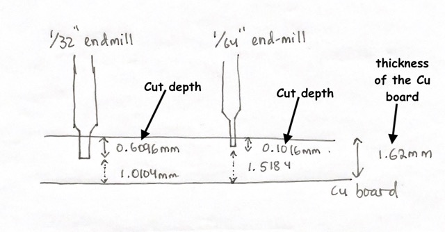
The cut depth is the depth at which the board is going to be cut. The cut-depth for 1/64 end-mill is 0.004in (0.1016 mm) and for 1/32 end-mill is 0.024in (0.6096 mm)
-
The cut-depth for the trace is lesser than the edge because the trace requires only little copper to be removed while for the edge the copper board thickness is to be considered such that the Copper board is almost cut hence it will be easier to take the board out with minimal damage to the sacrificial layer.
-
The offset number is the number of the times the board will mill . The offset number for the trace is 4 and for the edge is 1.
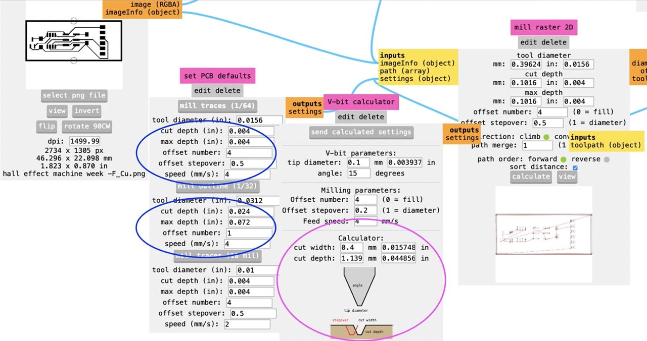
-
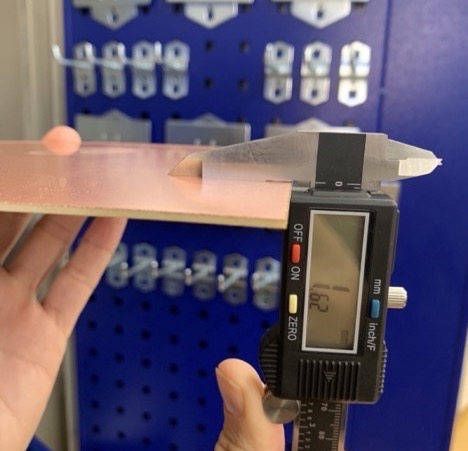
The thickness of the Cu board is 1.62mm
-
The size comparison
The rml file:
In VPanel for SRM-20 (To mill the board)
- Open the VPanel for SRM-20
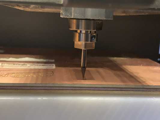
- To mill the traces, place the 1/64” end mill in the SRM20 and perform gravity
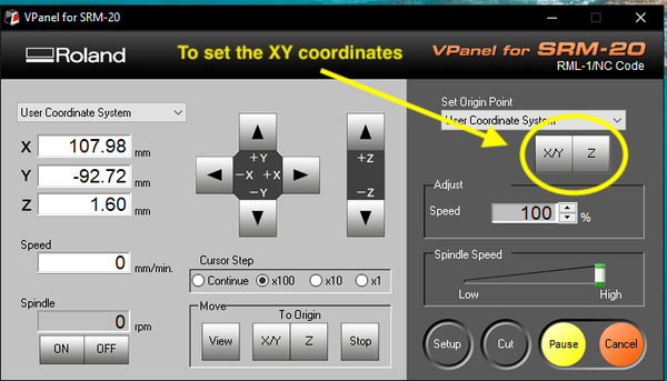
- Set the X/Y and Z coordinates for the board.
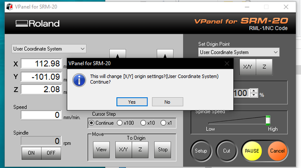

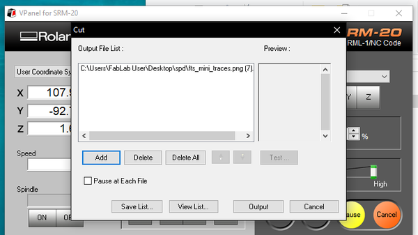
- Click on cut-> add-> Output
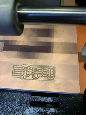
- Clean the dust from the PCB board and use a spatula to remove the the ISP board from the PCB
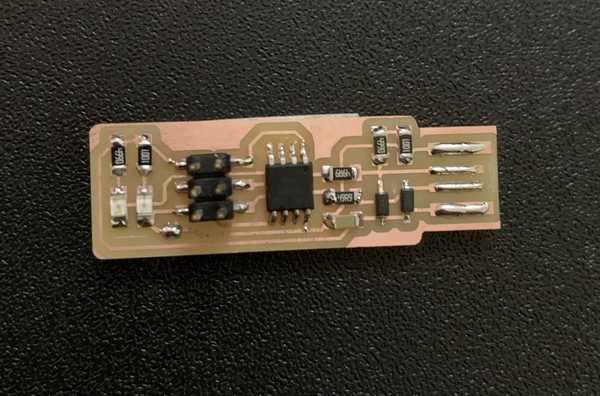
Assembling the PCB
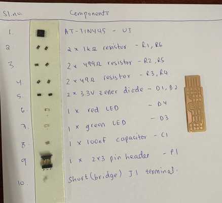
- Obtain the components
- Place the PCB board on a PCB board holder or a flat surface to solder the components on it
- Make sure the fumes extractor and the lamp is put on
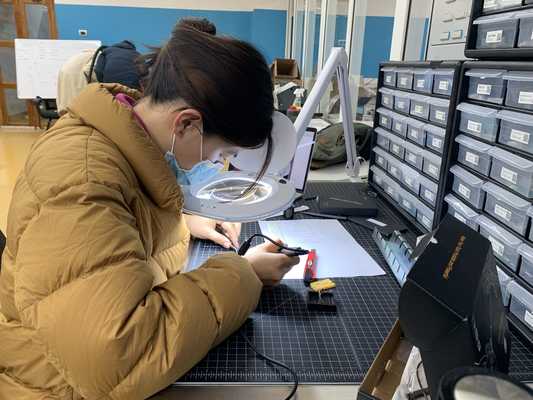
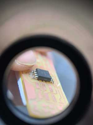
- Use magnifying glass to see if the soldering are done properly
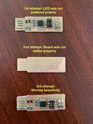
After soldering, the next day I programmed my ISP board but it would not work (sad). I milled another board but then the copper from the board was not milled properly (very sad). Keeping my hopes high, I tried again for the third time. Well they say the third time the charm and it worked at last (happy)
#Note:
While soldering i had to use magnifying glass to solder the components and to check if soldering was done properly but every time i used magnifying glass, i got bad headache.
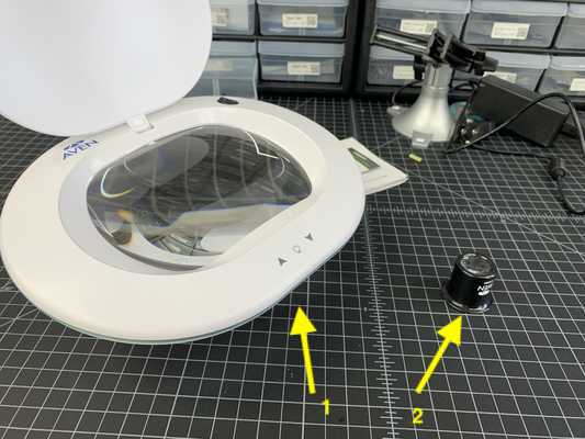
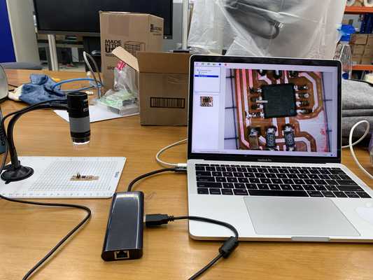
There are many types of magnifying glass in the lab. But i particularly liked the plugable digital viewer. I could solder the components and then check the connections using the plugable digital viewer and i didnot get headaches as i didnot have to look through the magnifying glass
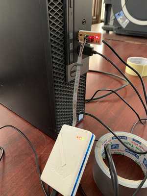
Programming the board (in ubuntu)
- Connect your ISP Board to the computer and the red LED lights when the target circuit is powered
- Download the firmware source code and extract the zip file Open your terminal program
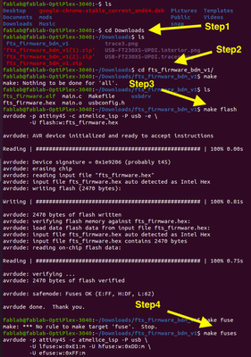
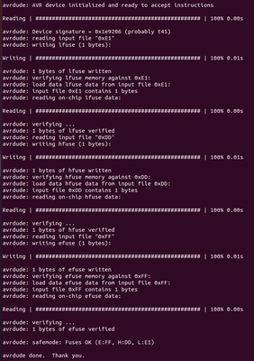
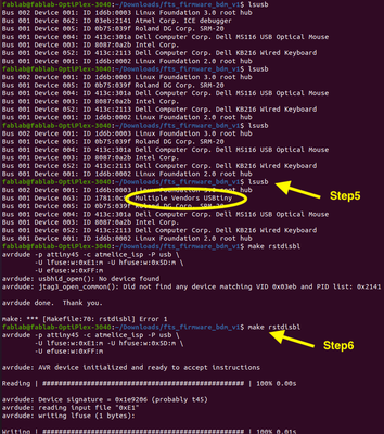
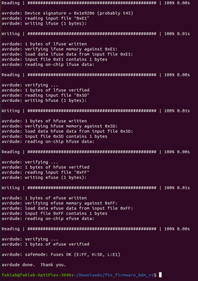
Connect your ISP board to the laptop and if the green llights lits in the atmel then the ISP board is working.