Checklist
Group assignment
MECHANICAL DESIGNMACHINE DESIGN
- Design a machine that includes mechanism+actuation+automation
- Build the mechanical parts and operate it manually
- Document the group project and your individual contribution
- actuate and automate your machine
- document the group project and your individual contribution
INTRODUCTION
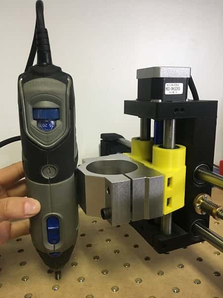
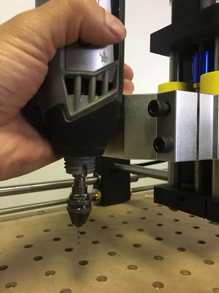
We realized that our lab needed a machine to drill electronic plates, a job that had been
done manually with a dremel lately. As a starting point we used a machine that our
tutor bought months ago but had not been used.
The machine seems to be working fine but we'll adapt it to do what we want.
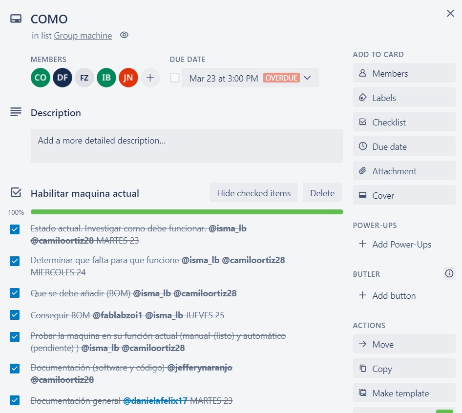
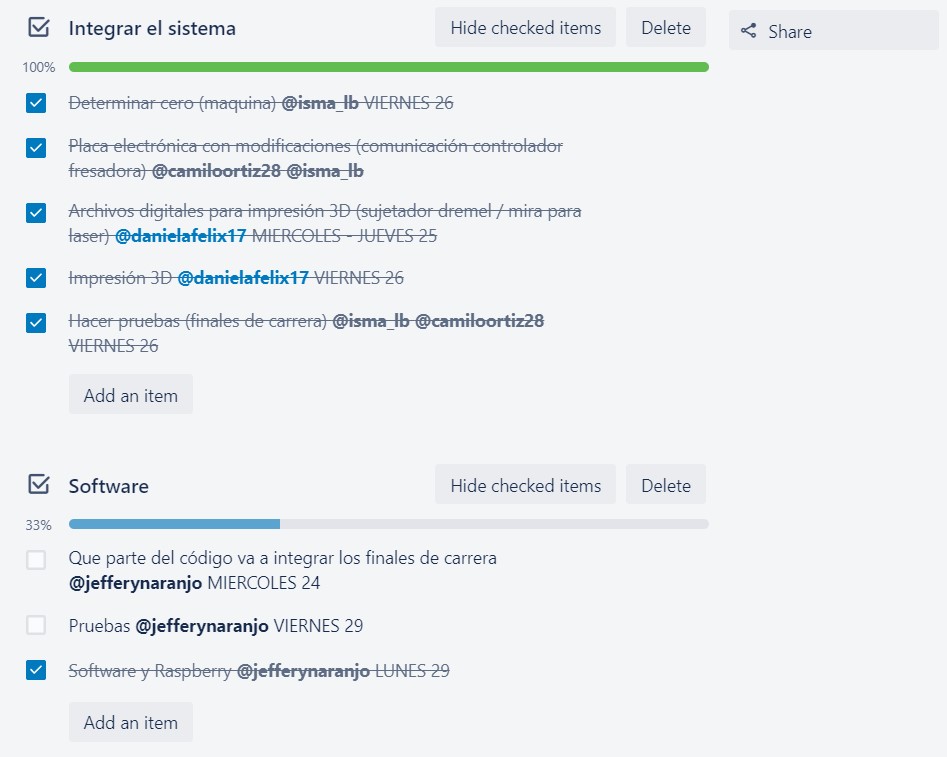
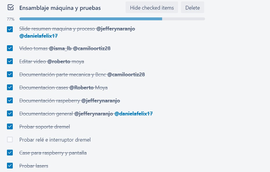
The following pictures show the planning we made for the machine design and execution, also who is responible of each part and when they are due.
For this we used Trello which is a free app useful to work on teams.
THE PROCESS
PHASE I - ENABLE THE MACHINE
We took advantage of our abilities and divided the work that needed to be done. Camilo and Ismael are in charge of the mechanical and electronic part, Jeffery in charge of the software and Roberto and Daniela in charge of the modeling and printing of the missing parts for the machine assembly.
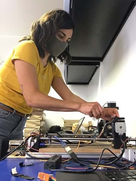
On our first meeting we verified that the machine works and we made a list of activities and responsibilities to meet the schedule.
The items to be done in this phase were:
- Check actual status and find out how it works
- Check what is missing for the machine to work
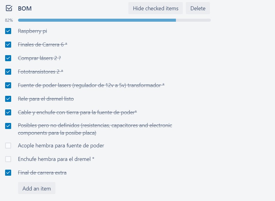
- Define and get the BOM
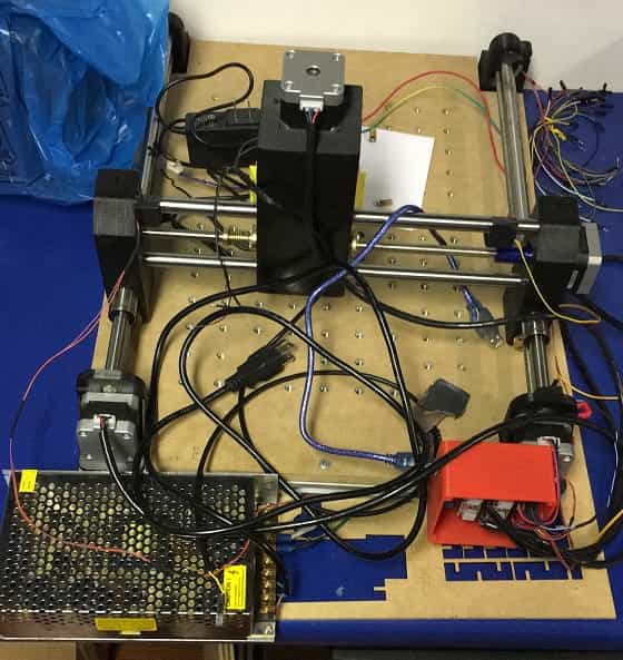
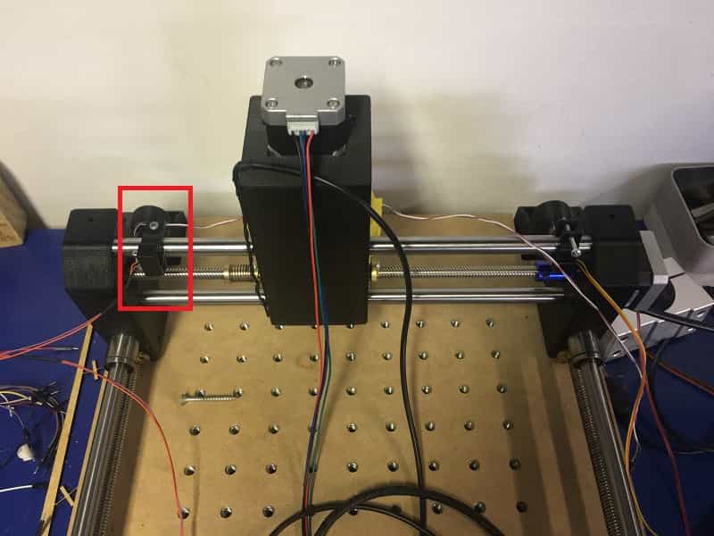
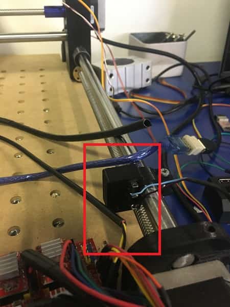
When checking the axis movement we note that the Y axis which is the longer one in this machine move too noisy, after some test the problem was that the sides of the the axis where no aligned. As the threaded Rod have just one side fixed the start position of each side depends in this design in the machanichal initial position when assembly the lead screws on threaded Rod.
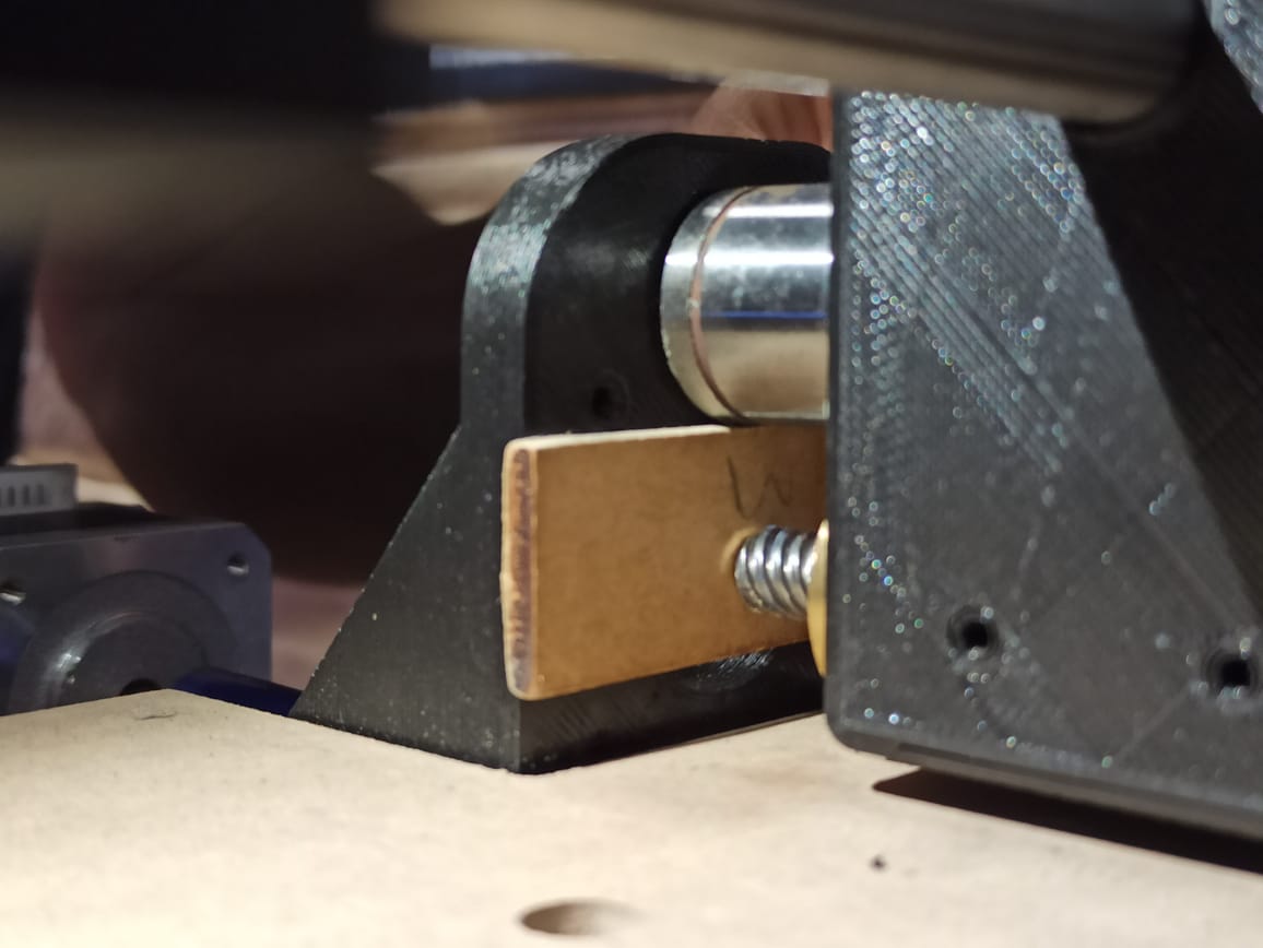
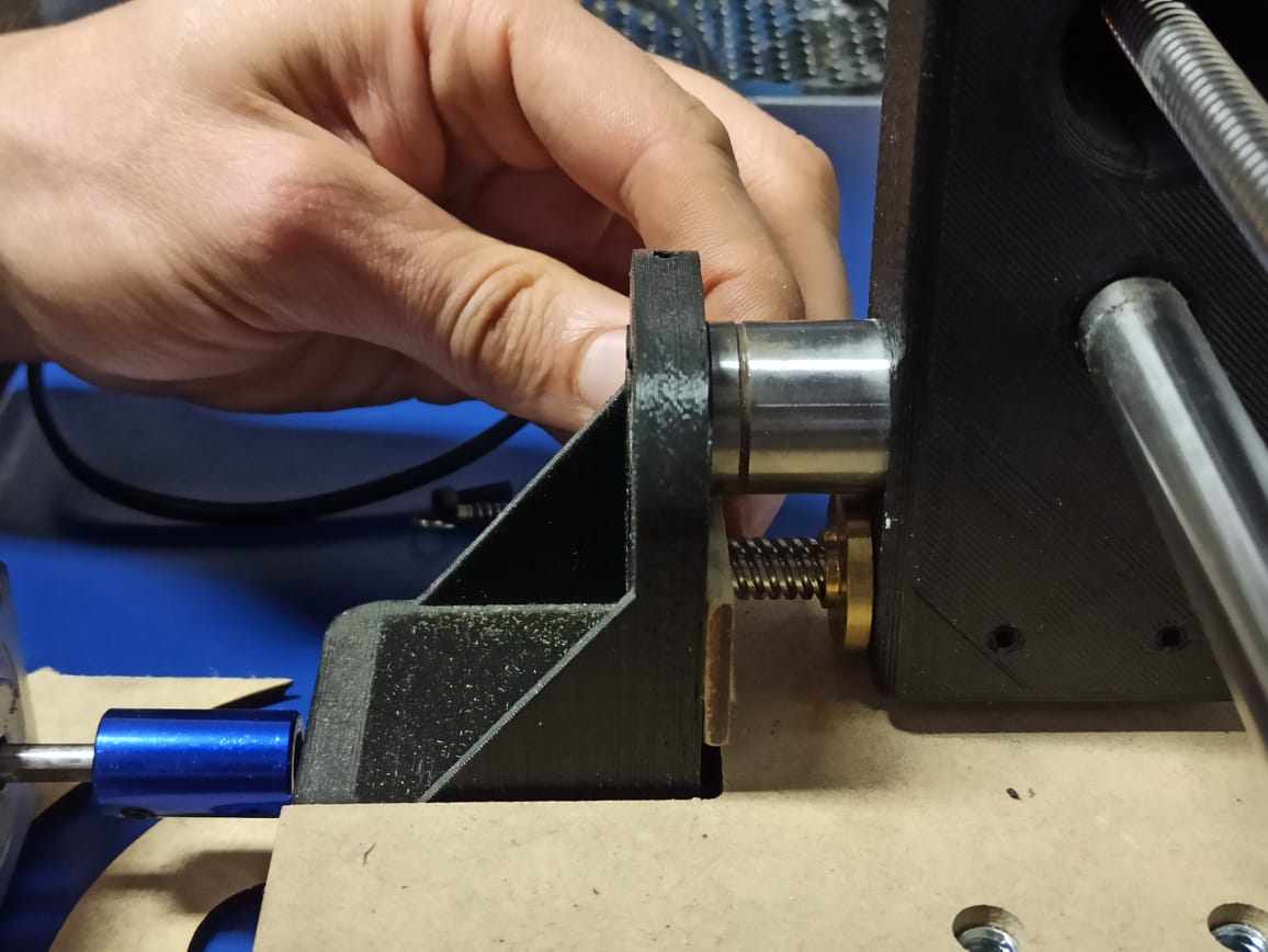
After this mechanichal alignment the axes of the machine move without problem and we have determined to use lasers so that the machine can identify the origin. We will use Bcnc to control it.
BOM
- Raspberry-Pi
- Endstops
- Lasers
- Phototransistor
- Electric outlet for the dremel
PHASE II - INTEGRATE THE SYSTEM
Time to get to work, these are the activities that we determine for this phase:
- Find out the 0,0,0 of the machine @ismael and camilo
- Electronic board modifications @ismael and camilo
- Design and 3d print dremel holder, cable clips, end stops supports and sights for lasers @daniela
- Software and raspberry @jeffery
- Design and 3d print power case, emergency stop and arduino case @roberto
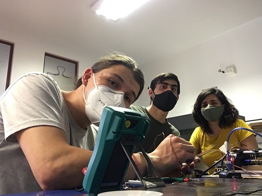
Making the circuit board @Ismael and Camilo
As our machine was centered around laser-zeroing we need to 'hack' the limit switches, as we hope that the laser can add precision on top of the physical switches by eliminating the bounce effect issues.
The board has to be capable of sensing when the limit switch is pressed and turn on the laser and then sense the interruption and act as a limit switch.
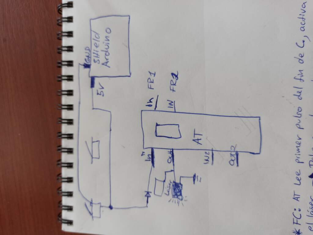
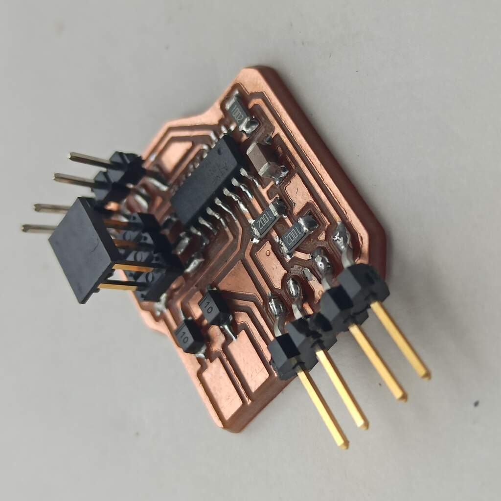
With Camilo we sketch a simple diagram that uses the ATtiny44 as source of logic some pulldown resistors for the phototransistors and some diodes to make sure the board does not interfere too much with the sensing from the Arduino UNO .
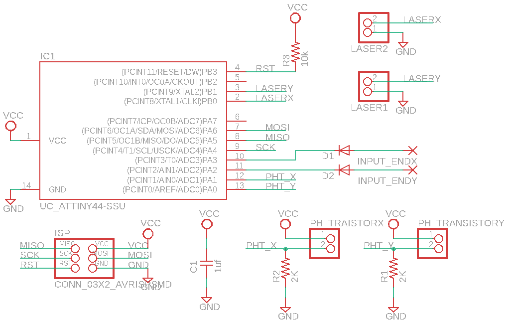
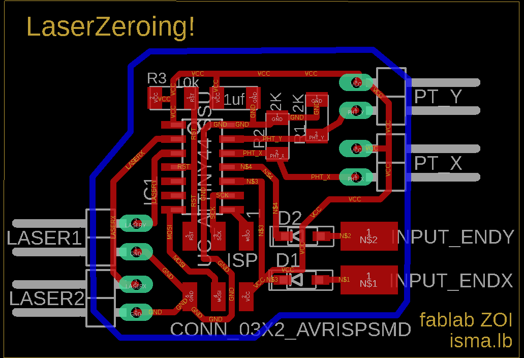
Using Eagle we place the required components and start routing the traces. This process takes me always a while, figuring out the best way to make the traces is difficult.
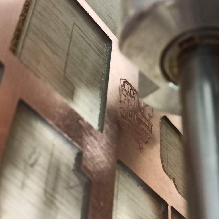
See the board outline See the board traces get the Eagle .sch file get the Eagle .brd fileUsing Mods we generate the G-code needed for the traces and start milling, our first attempt was a failure because we were using wrong the auto-level on the bCNC (software that controls the CNC milling machine). But after some research on the internet, we manage to use a new workflow and use the auto-level properly. The result was that the mill bit only engrave the surfaces of the copper layer and did not crate the traces.
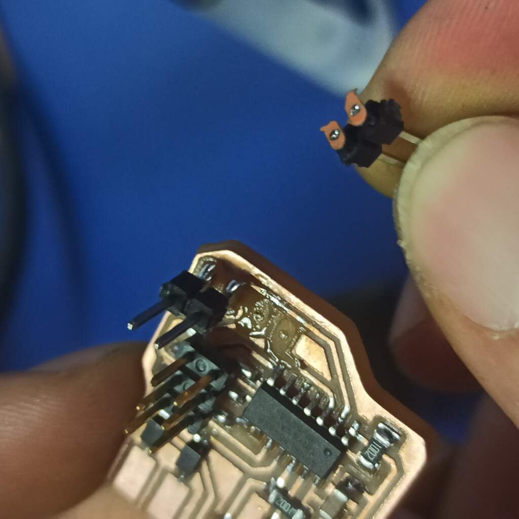
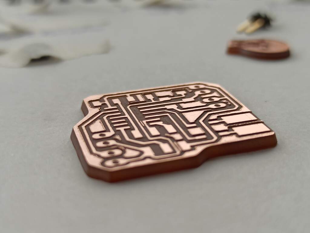
After adjusting the cut depth on the g-code using the same workflow we finally make a good looking circuit board.
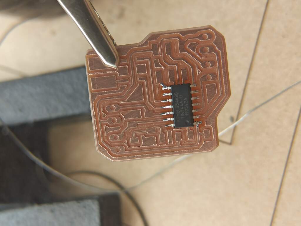
Then the next step was to solder all the components, I started by the micro controller unit, followed by the capacitor, the resistors, diodes and finally the pin headers for the ISP connections.
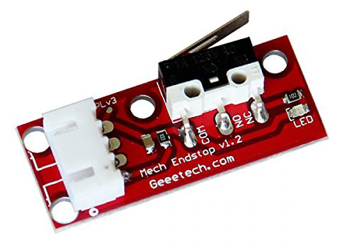
End Stops Limit Switches
End-stops can also be used as limit switches which prevent the machine from attempting to move beyond the physical limits of the axis (by pausing/stopping movement when triggered), see the Endstops page for details about configuring Smoothie to use End Stops as limit switches.
The cnc shield offers us the necessary pins to connect our end switches but if we need to install more we could make a parallel connection
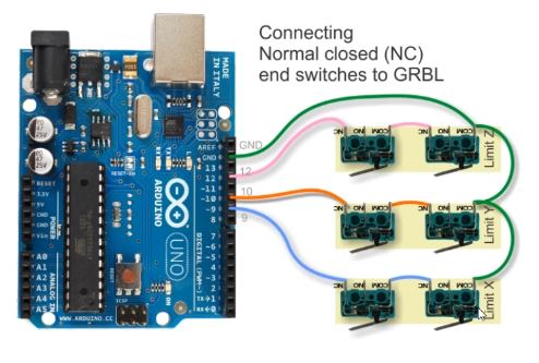
Connections for Arduino Mega

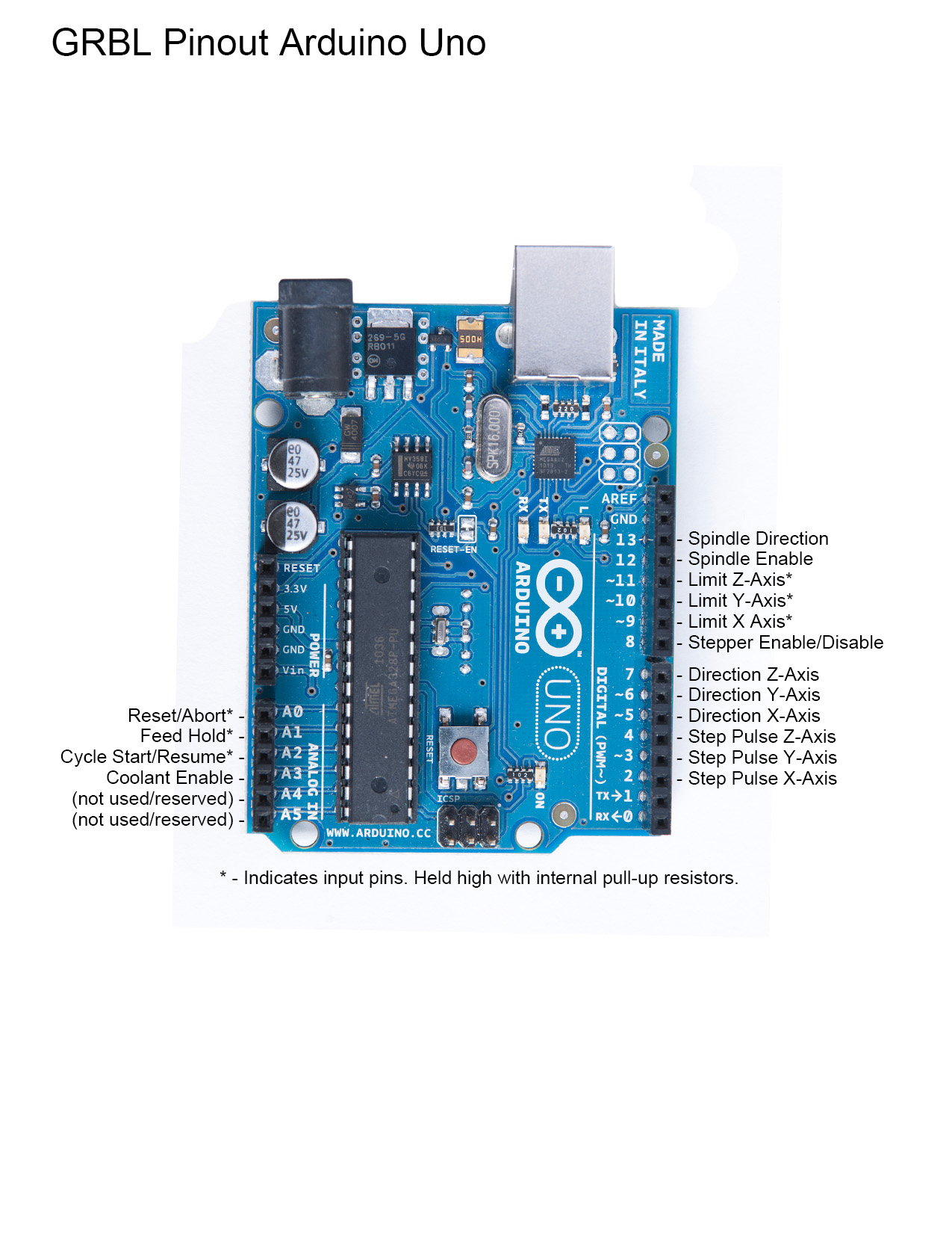 In this link you can download the GRLB cnc controller code Download
we can find the pins in each case in the GRBL file gcode_h
In this link you can download the GRLB cnc controller code Download
we can find the pins in each case in the GRBL file gcode_h
DESIGN AND PRINT @Daniela
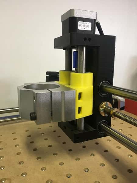
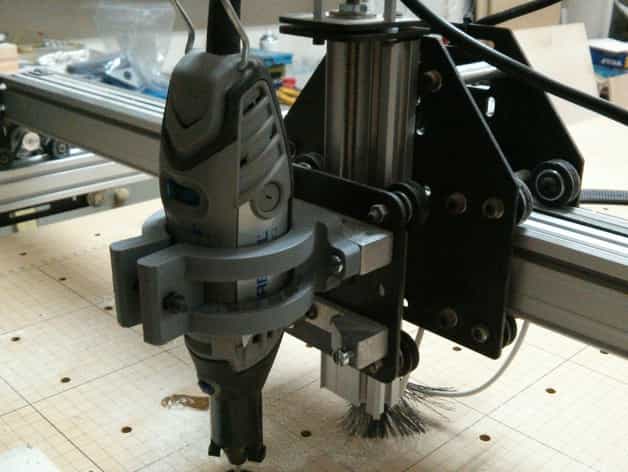
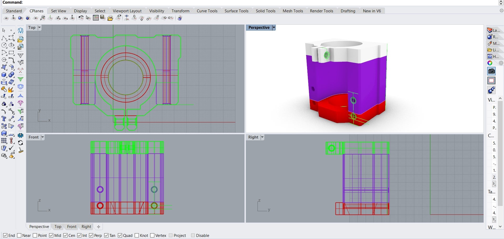
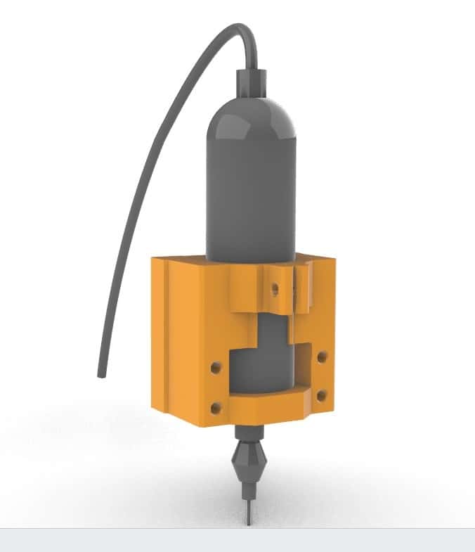
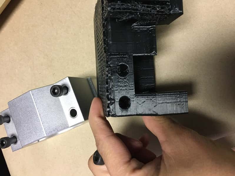
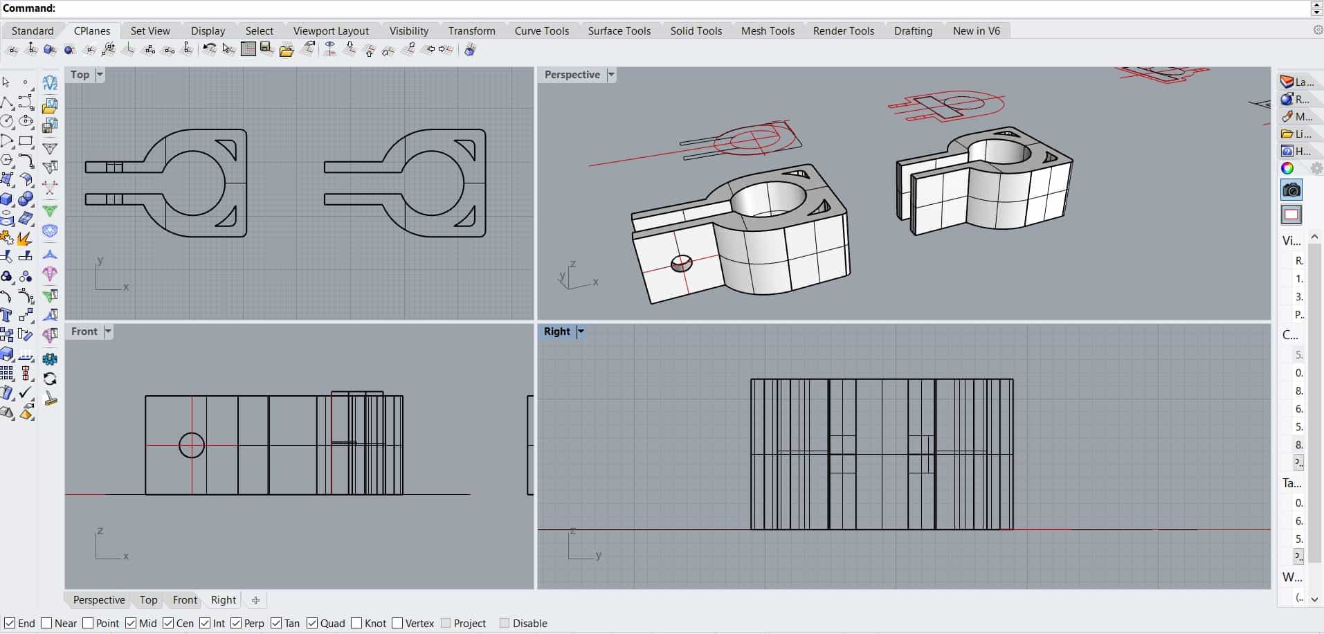
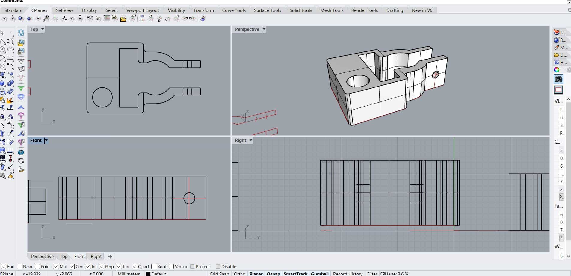
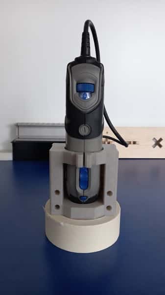
I was in charge of the design and printing of some pieces. I started with the dremel support, taking as a reference the support that was built into the original machine to take advantage of some of the parts. I replicated the measurements and adapted them to the dremel that we have in the laboratory and that will be used to make the drillings.
I looked for an existing model on thingiverse to see how other people have faced this same situation.
You can find this model here:
Dremmel3000 mount.
Then mixed this design with the existing piece in order to maintain the location of the support bolts.
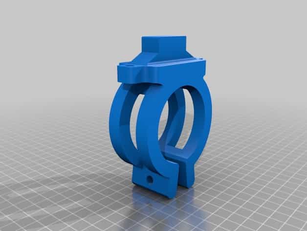
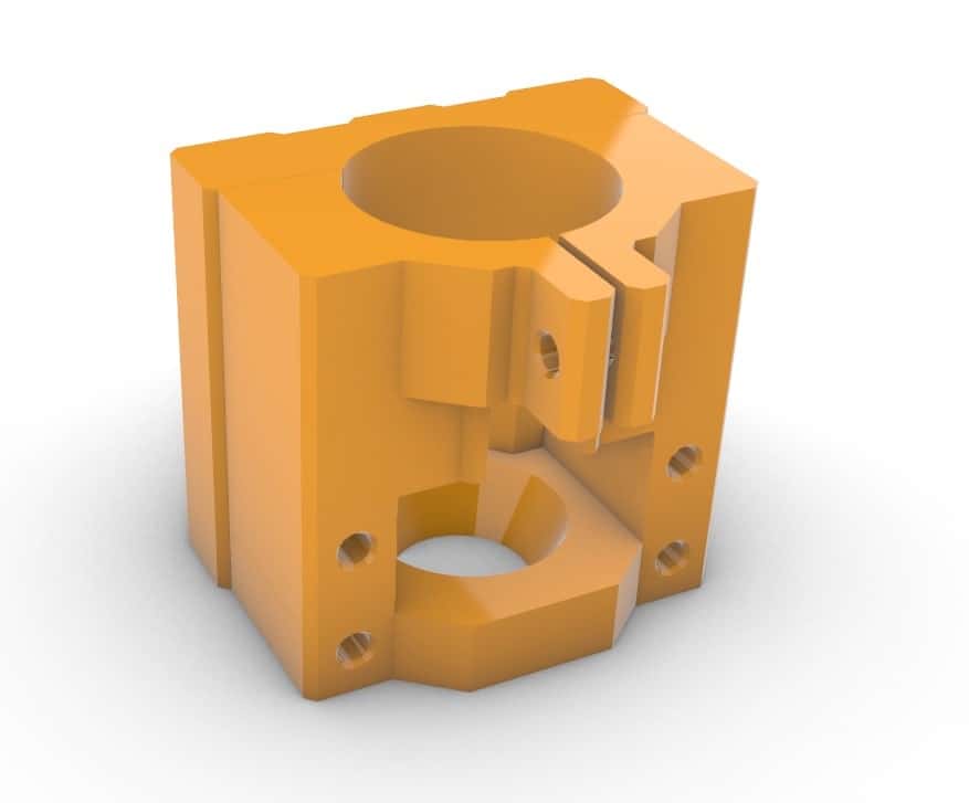
This was the first result:
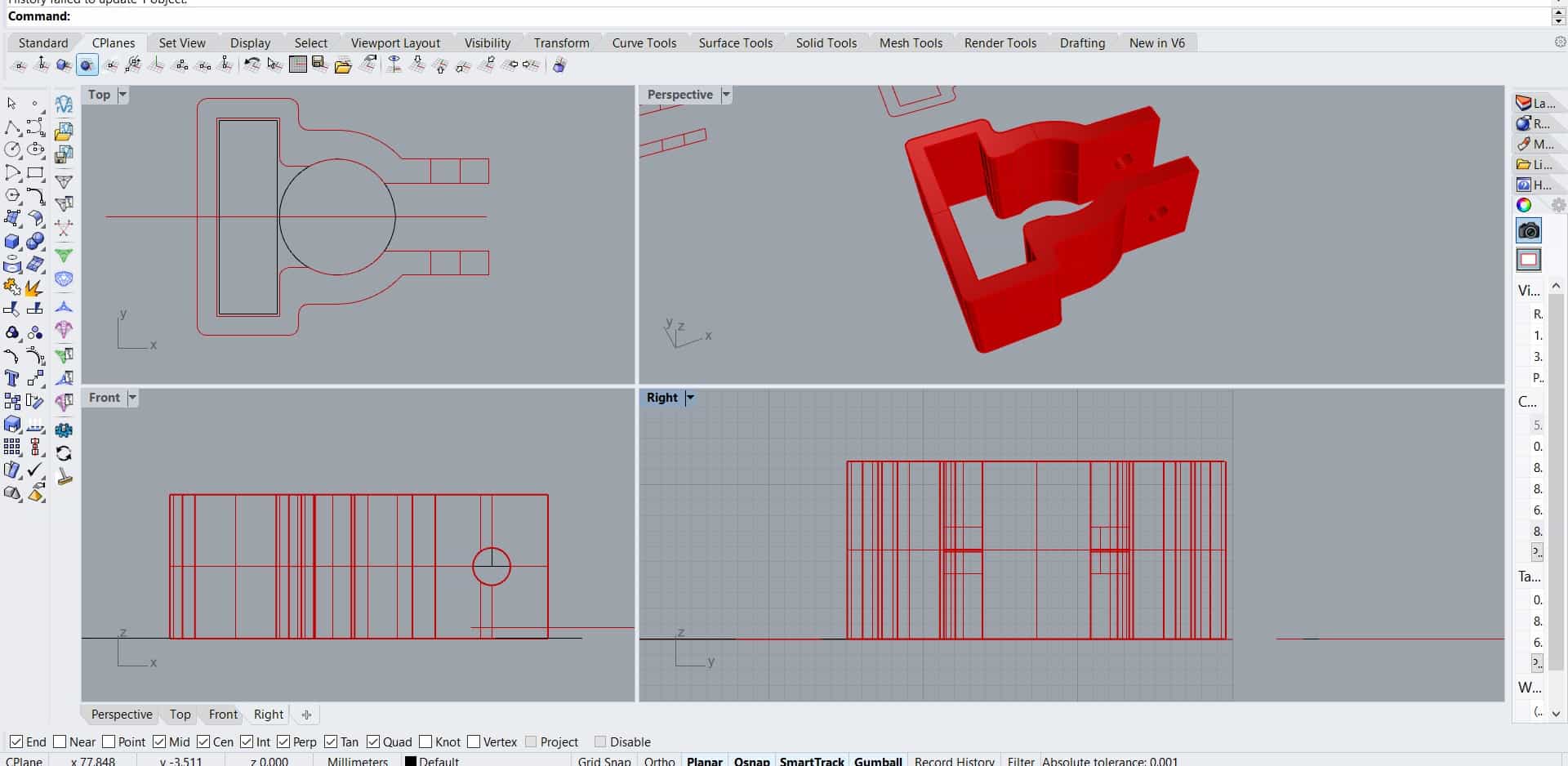
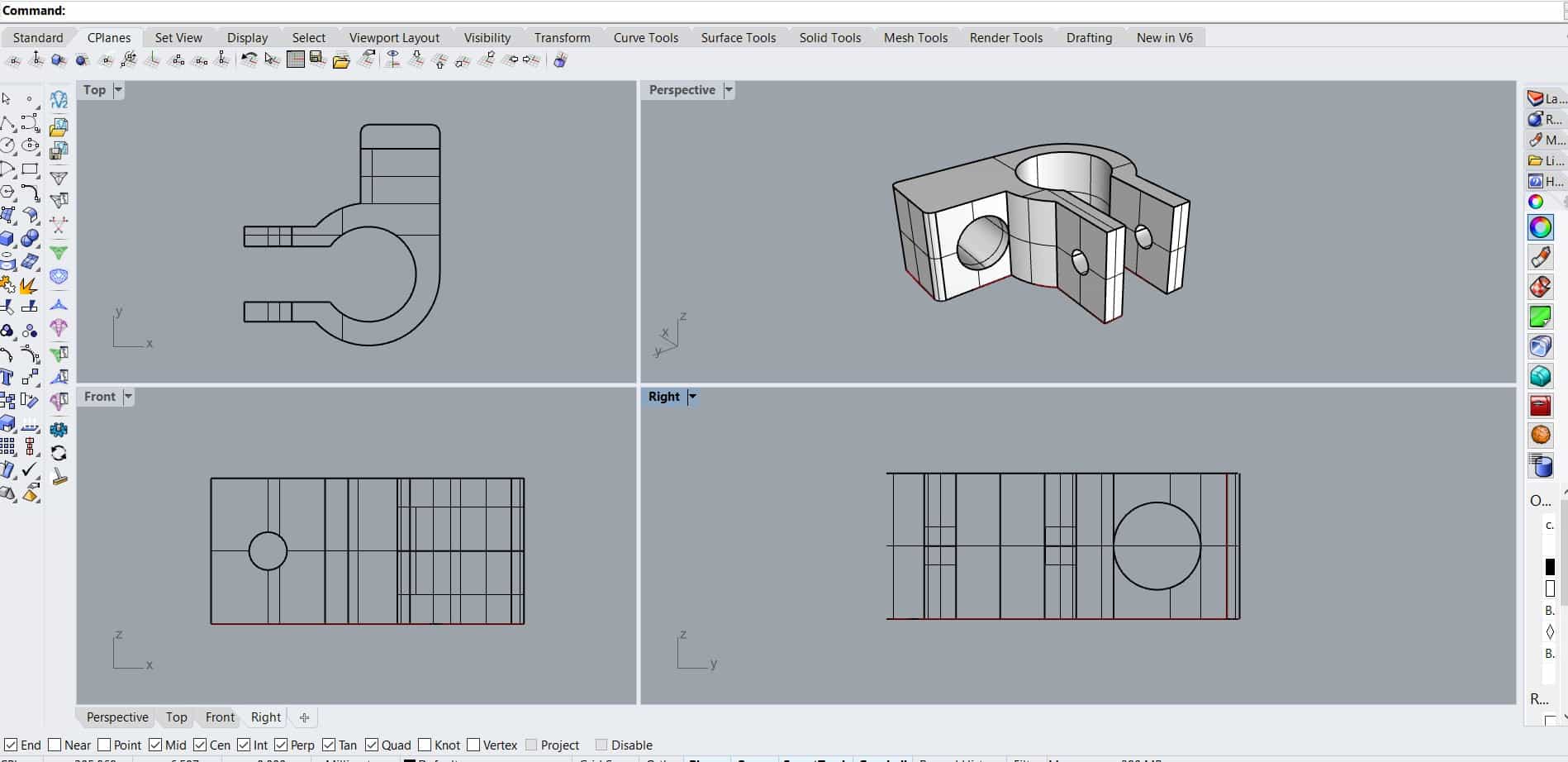
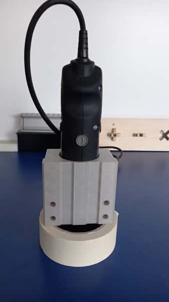
For the following modifications, I made a conical support at the base to suit the dremmel, lengthened the
height to provide more support, an intermediate clearance for ventilation and a lock on the top.
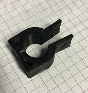
Printed this model, but during the process the power went out and only had half of the piece.
This was helpful because it allowed me to make some measurement modifications to the model.
I realized that the temperature with which I was printing was too high and this was generating a
deformation in the overall dimensions of the piece, making it longer, affecting specially the bolts
perforations making them barely reach to enter the support.
The conical base fitted perfectly. The diameter of the top bracket of the dremel was insufficient
and I noticed that it is not cylindrical but oval. In general I added more tolerance for the pieces.
The complete printing process of this piece takes around 11 hours so I decided to focus on the other pieces during
our day at the lab to be more efficient with the time we had to work together. We needed to
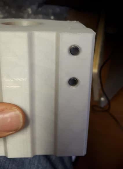
fasten the limit switches to the shafts and for this I looked for some inspiration on thingiverse.
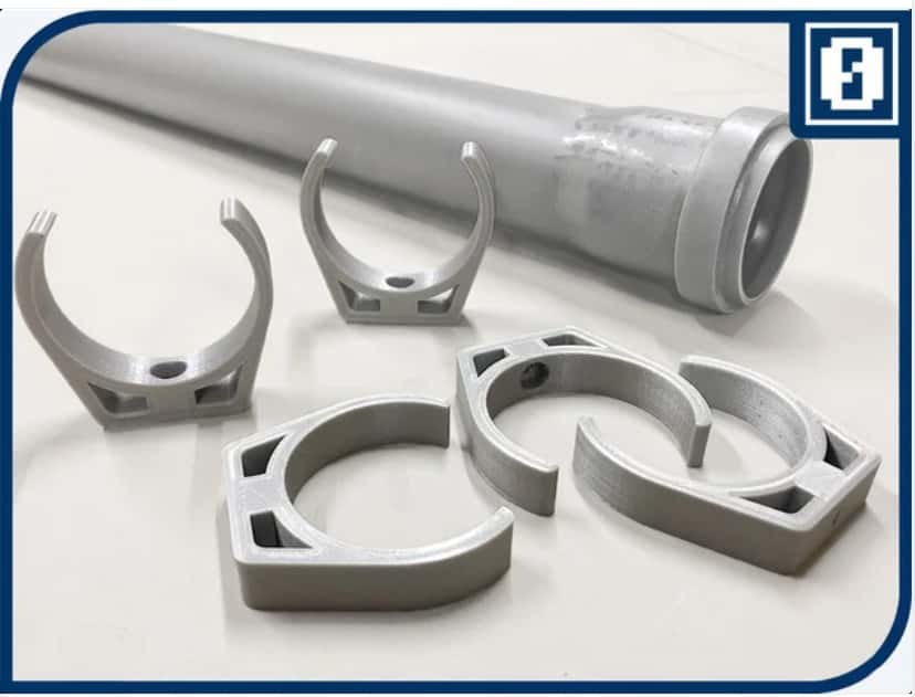
These are some of the models I based mine on:
Parametric pipe clamp.
Pipe clamp snap on one screw.
PVC pipe clamp.
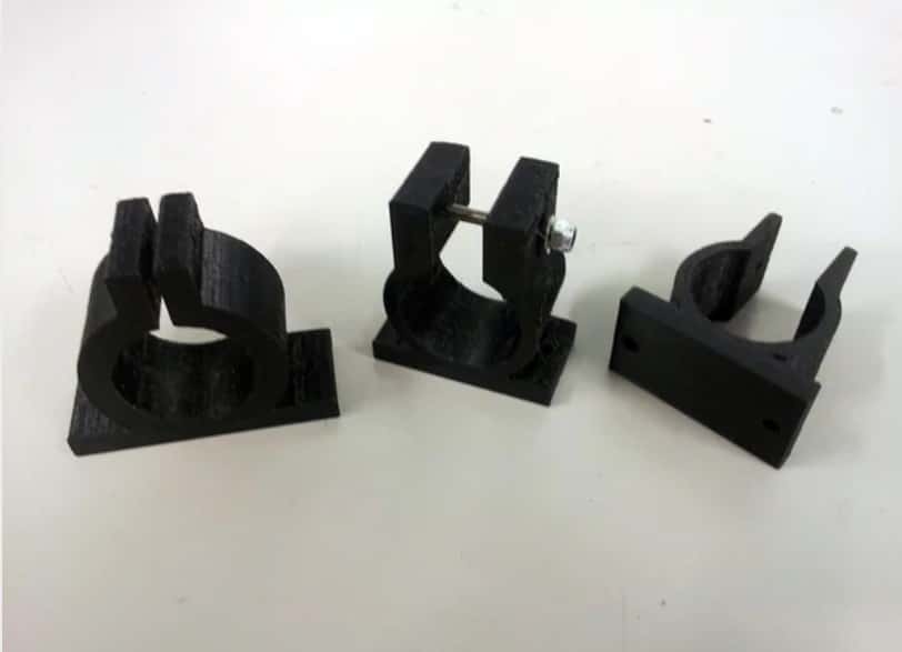
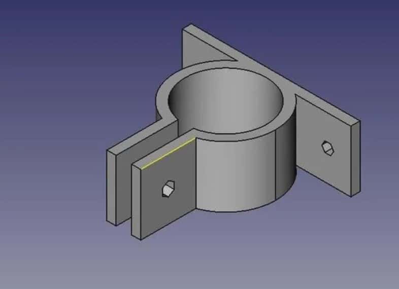
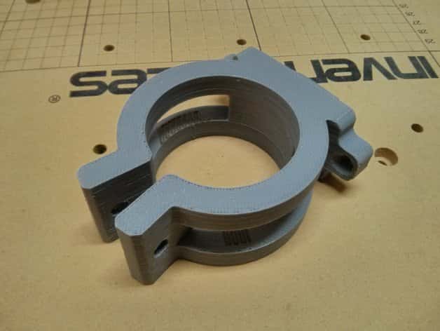
The first one I printed was too tight, and when we tried it, it broke a bit.
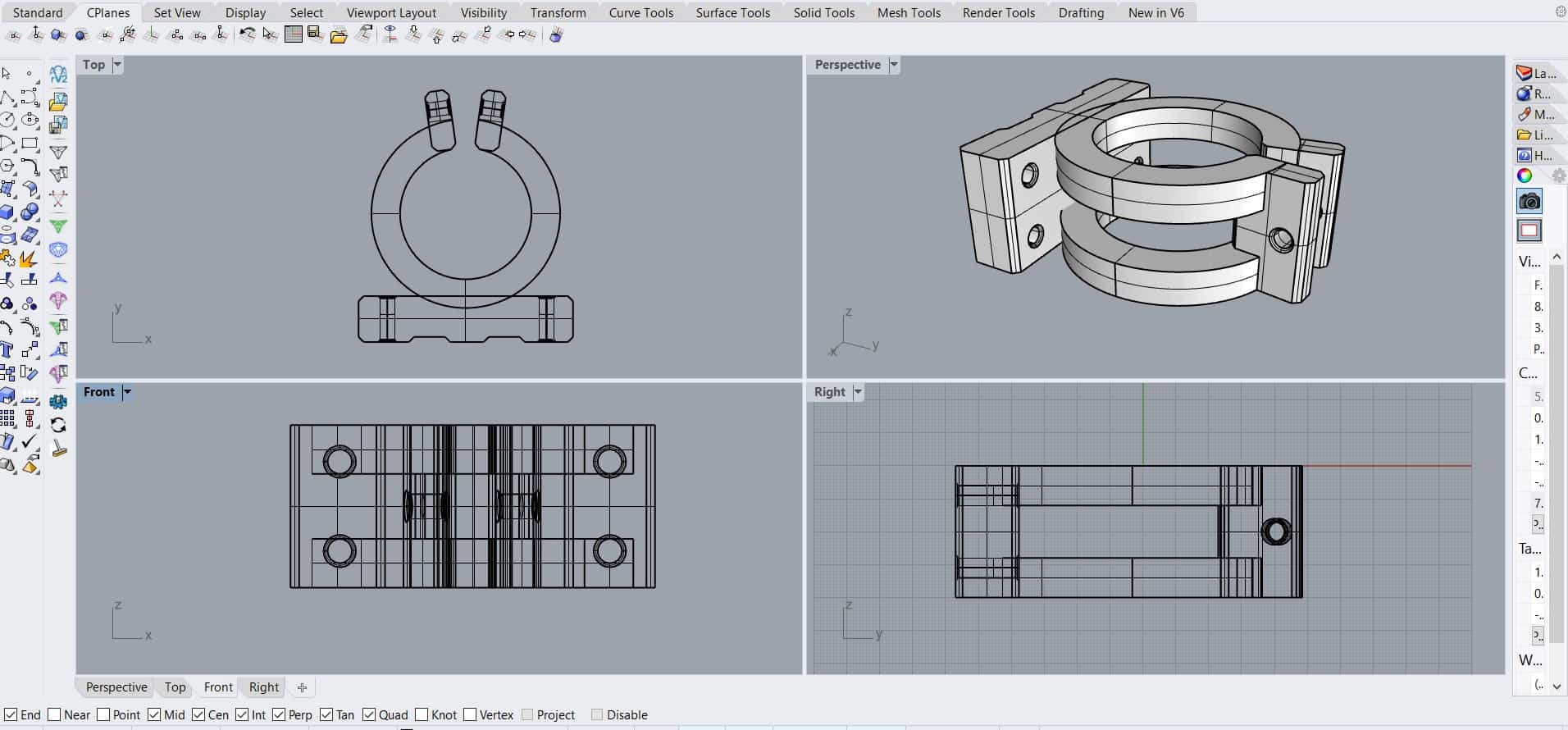
I modified the diameter of the shaft, added the limit switch on one side to make a single integrated piece.
It fit perfect for what we needed.
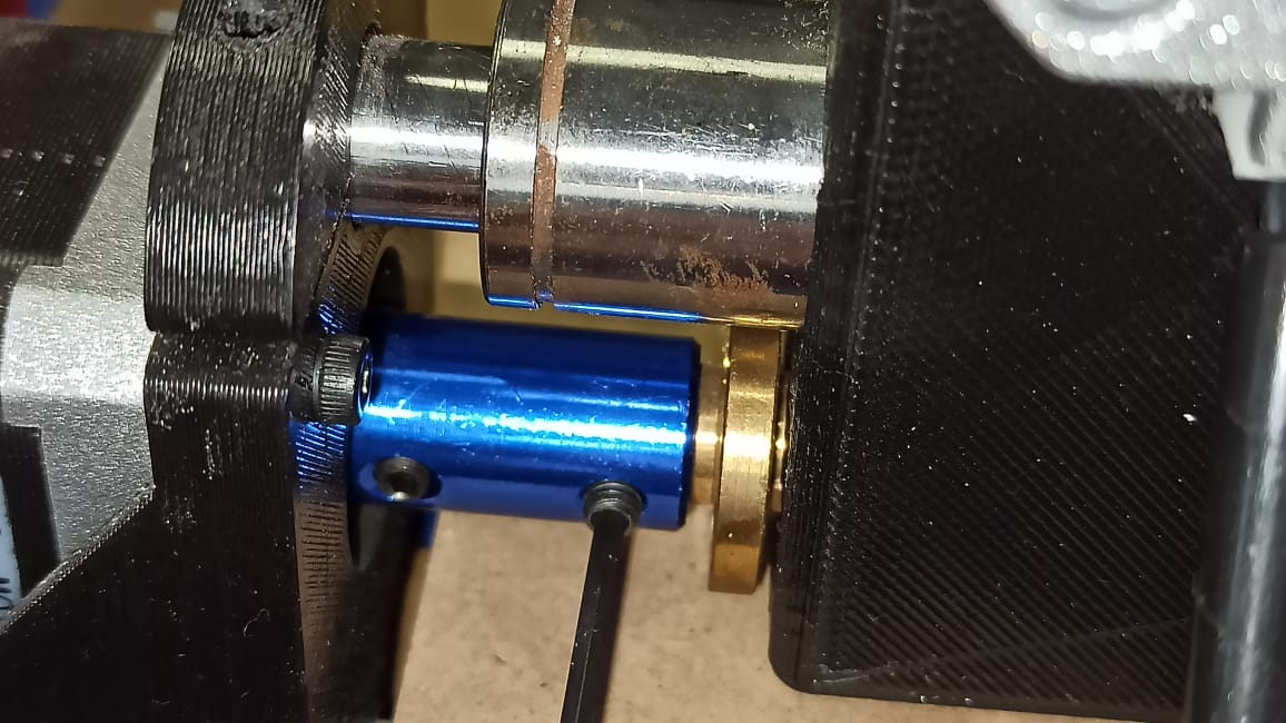
Two of this supports needed to hold the laser, I adapted it for both axes.
The next piece is designed to hold the phototransistor that responds by matching the laser.
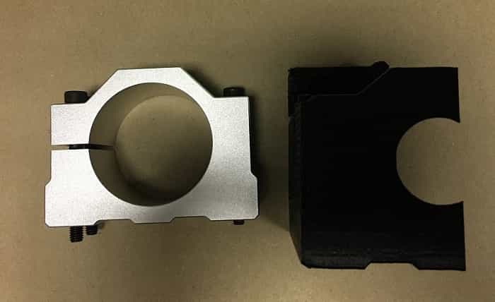
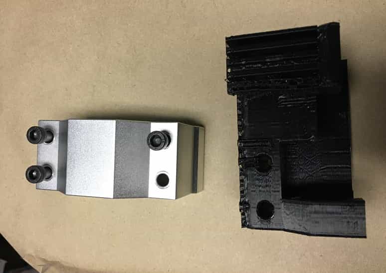
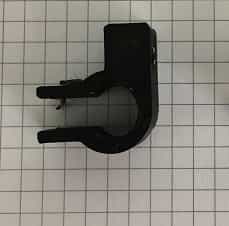
Printed once more the dremel support, this is the result:
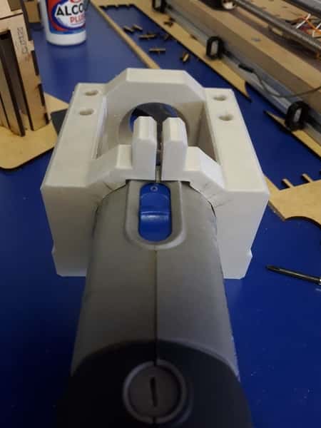
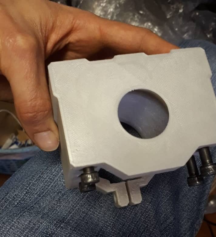
The dremel still doesn't fit, once more increased the diameter measures, reduced the total depth of the piece,
increased the diameter for the bolts and this is the result:
FILES
Here you can find the files we used for the 3d printed pieces
End stopsCables holder
Dremel holder
Laser holder
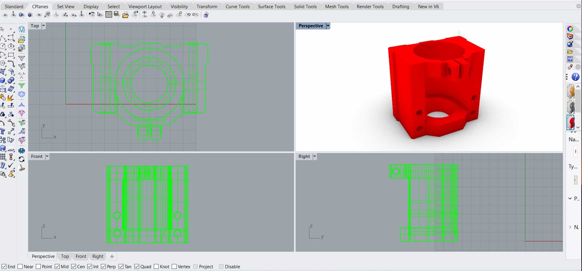
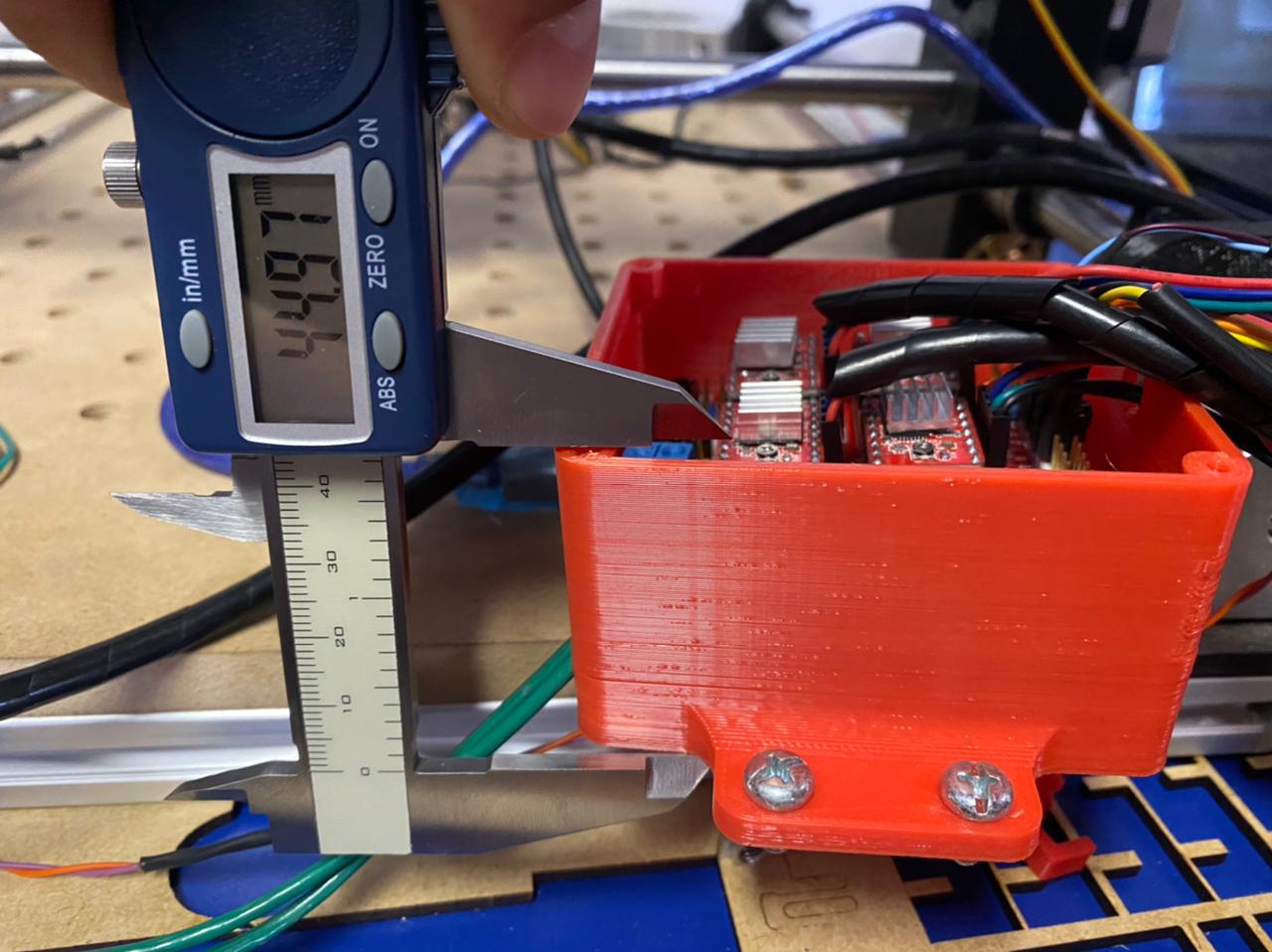
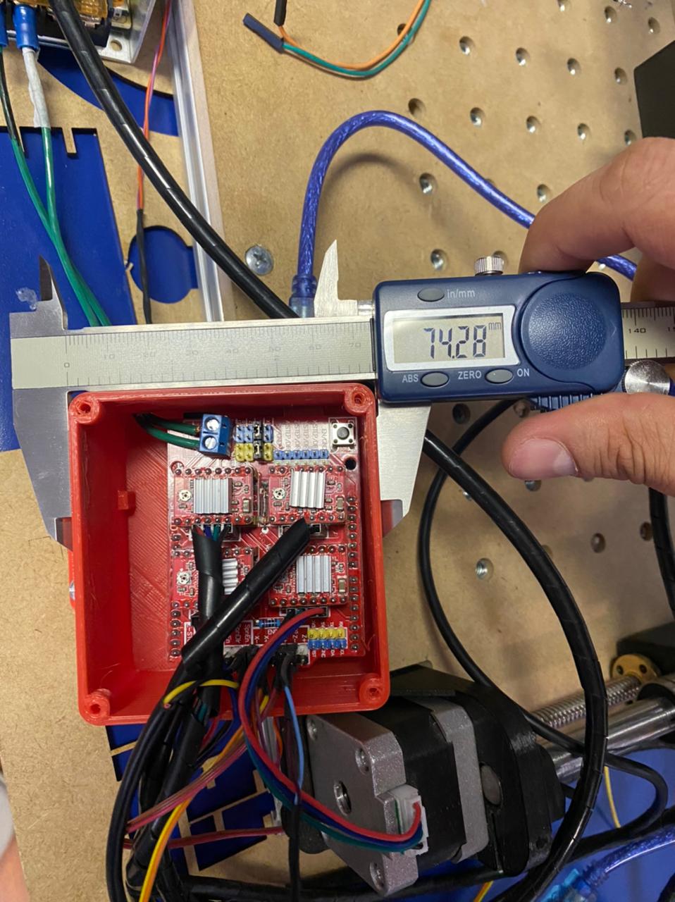
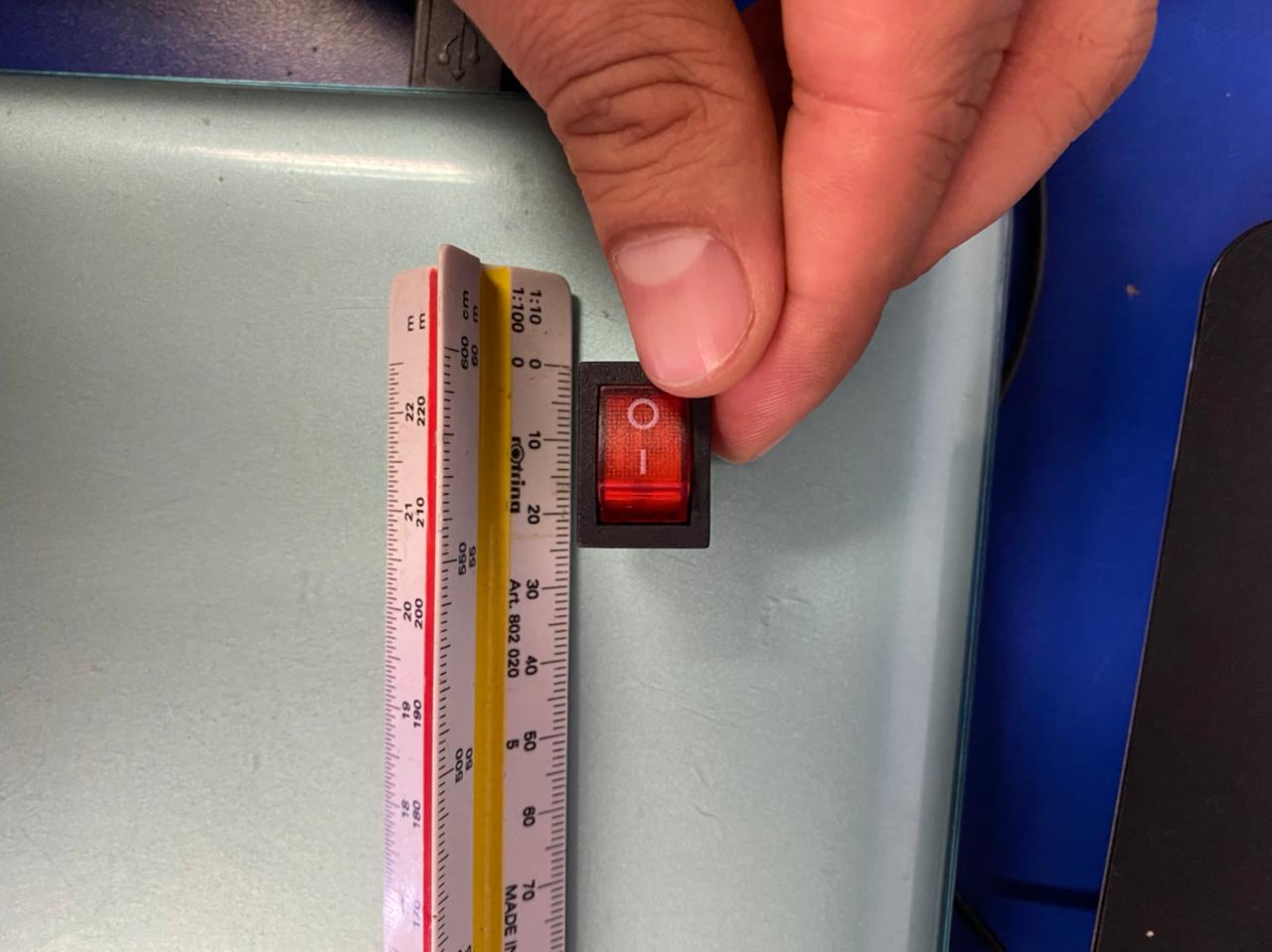
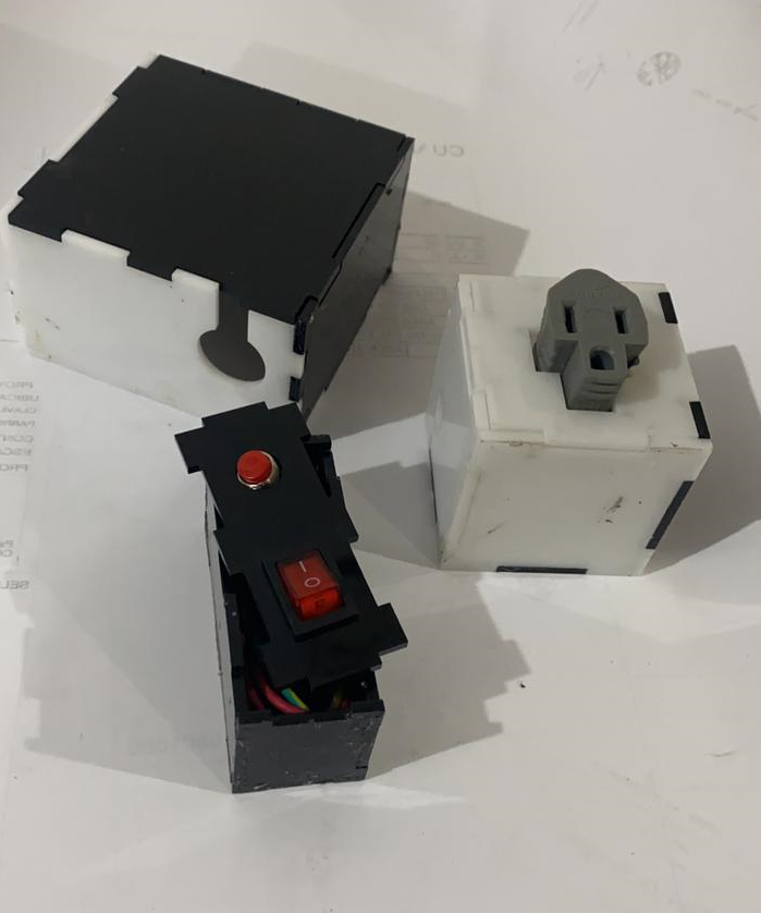
DESIGN AND PRINT @Roberto
@RobertoMoya has been in charge of the design and implementation of the cases for the electronic components of the machine. Thanks to his experience in 3D modeling and design, there was no problem in both design and manufacturing.
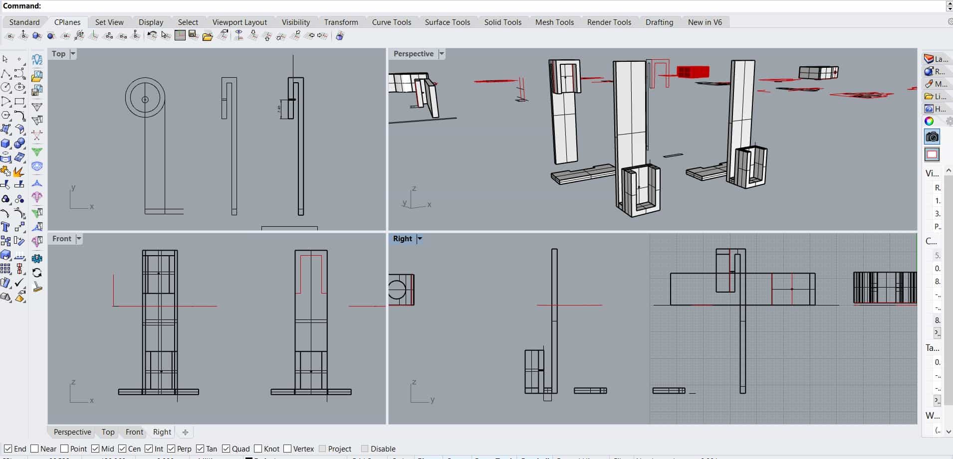
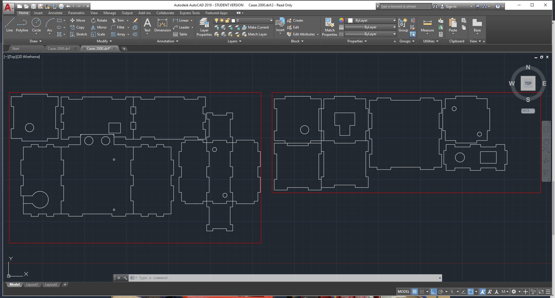
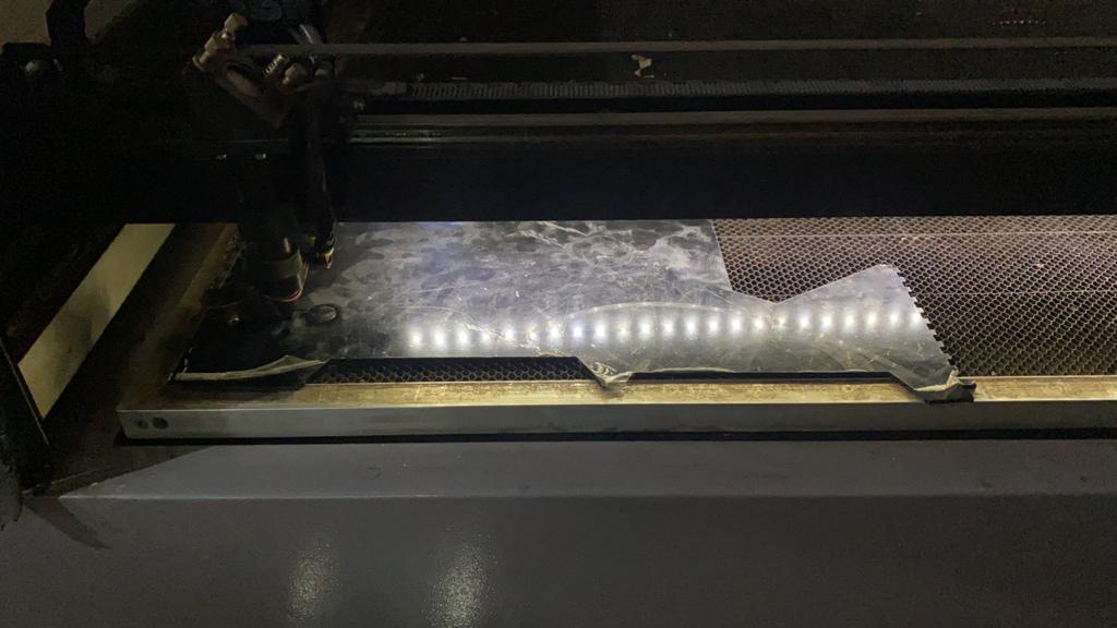
Initially, it was thought to make the manufacturing through 3D printing, however, in order to practice the techniques learned, it was chosen to manufacture through the laser cutting process, so it will greatly optimize the manufacturing times. For the design process, the 2D AutoCAD design software was used, in order to train skills in this software, no other tool such as Maker Case that could have streamlined the design process is used.
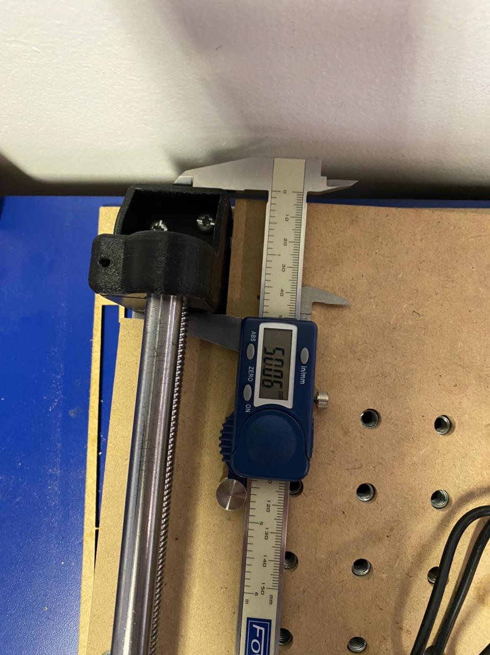
Before proceeding with the design, we obtained the dimensions of the existing components and were able to improve and adapt them to our needs.
Design in Autocad
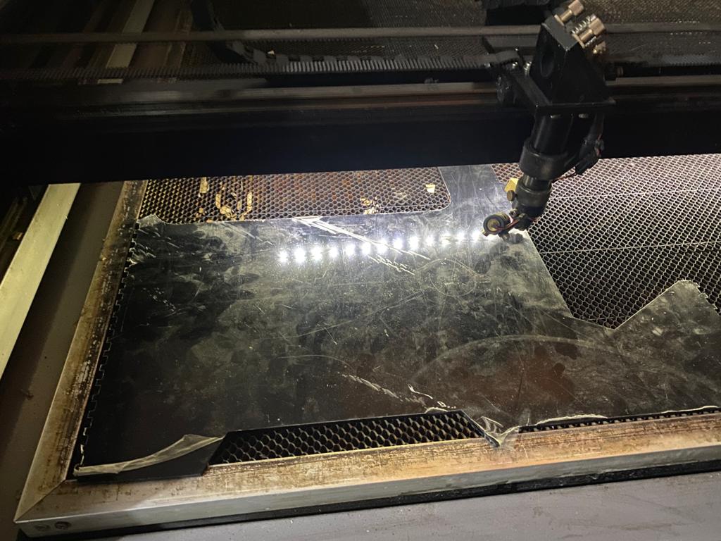
Manufacturing process by laser cutting
Case completed
PHASE III - SOFTWARE
In order to control the machine we decided to use bCNC, this is the process we followed to get the machine going:
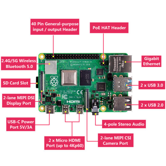
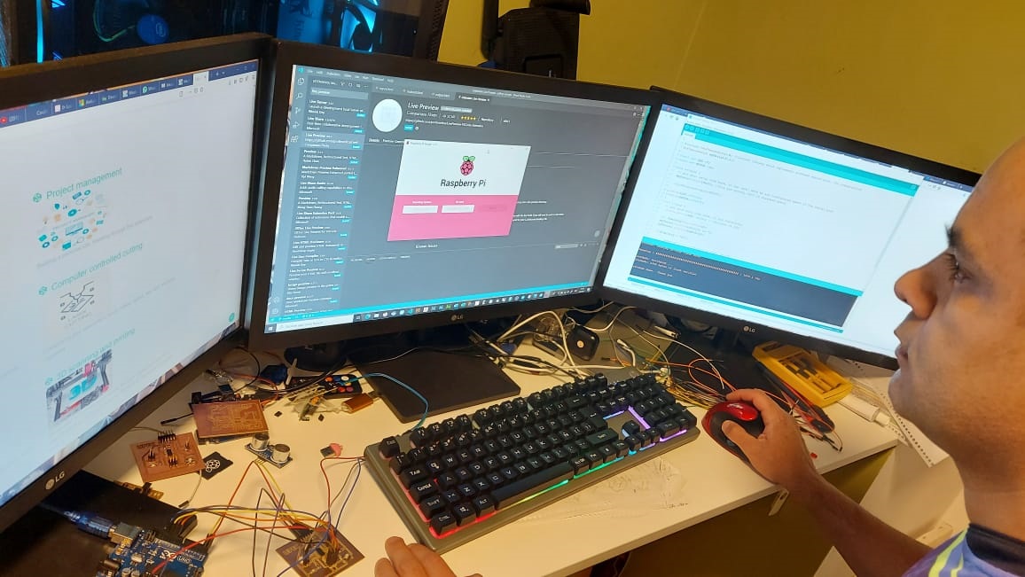
Using Raspberry Pi @Jeffery
Raspberry Pi, is a "it's a credit card size computer that connects to your TV and a keyboard." It is a board that
supports various components necessary in a common computer. ... These ports allow you to connect the minicomputer
to other devices, keyboards, mice, and displays
Installing operating system @Jeffery
To install the operating system on our Raspberry we will use Raspberry Pi Imager that we can download from the following link Raspberry Pi Imager Once we download and install it, we can choose the operating system that we want to install. this will be installed in a micro usb memory
For this assignment we will install the 32-bit Raspberry Pi Os which is a linux-based operating system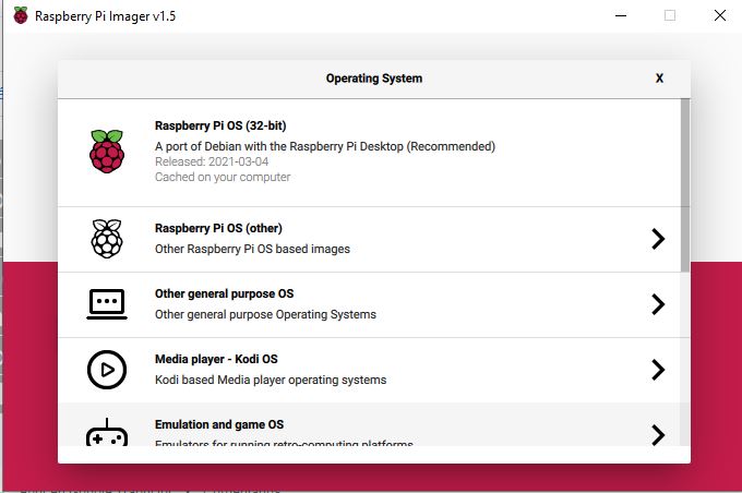
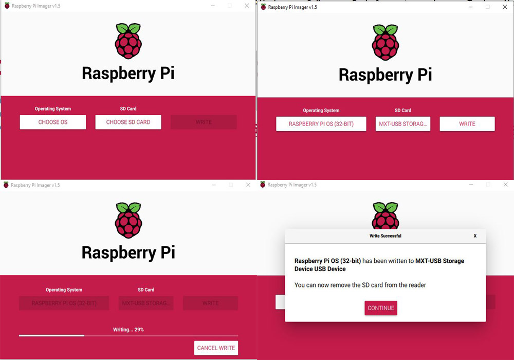
Once the installation is finished, it is necessary that our Raspberry has an internet connection, this can be by cable or through WiFi
To control the cnc we will use an arduino in conjunction with a cnc shield, the problem with this is that we cannot send large files, so we will use the Raspberry, for this we will install the Bcnc software, doing the following steps, remember we are in linuxInstallation (using pip = recommended!)
This is short overview of installation proces, for more see the bCNC installation wiki page. This is how you install (or upgrade) bCNC along with all required packages. You can use any of these commands (you need only one):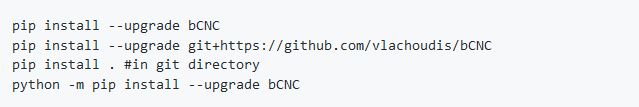 This is how you launch bCNC:

Programming
The ATtiny44 used on the board need to be programmed to achieve the laser and end switch sensing and react accordantly. I first start using Platformio to write the program as is easier for me use VS code that writhing inn the ArduinoIDE, but some how the SoftwareSerial.h wasn't working on the ATtiny44 when programing with Platformio. And that force me to move to the ArduinoIDE.
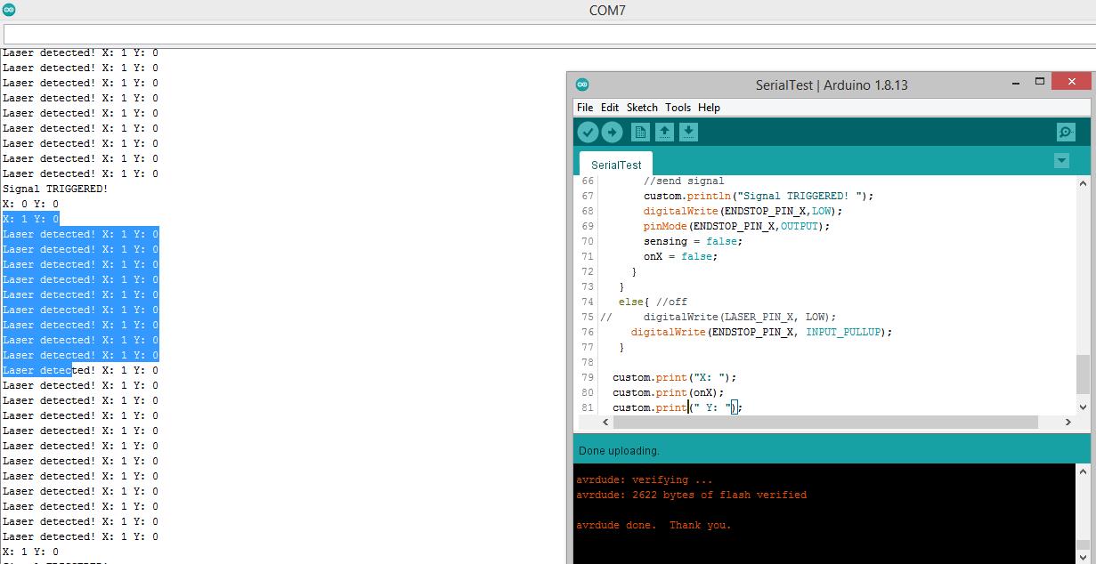
The first step was to make and analog read on the phototransistor pin and establish an approximate threshold to discriminate when the laser was pointing to phototransistor.
The complete code was a bit difficult because you have to check both axis on the same time so it can't uses any delay() function.

After some test it was working as intended but the program wasn't turning the signal off once it was sended, this bug take me a while to solve. I initially think that the state machine of the code was some how on and infinite loop. But after a lunch brake I finally catch my mistake it was a digitalWrite(ENDSTOP_PIN_X, INPUT) where it should be pinMode(ENDSTOP_PIN_X,INPUT)
Get the .ino fileUSE OF bCNC SOFTWARE
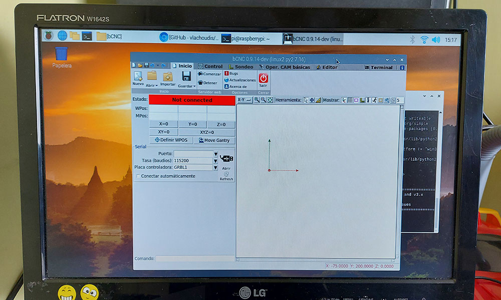
You can find a guide of how to install this open source Sotware HERE
bCNC is very usefull and there are a lot of information about it which is really helpfull. I will do this guide accross the steps on this tutorial if you want to watch it.
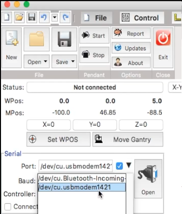
Connect to serial
It's important to mention this software is intended to use as GRBL CNC command sender and GRBL is recommended to work with Arduino so we are going to connect with the same COM port Arduino is connected as shown in the image below.
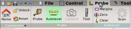
In the top bar we can find different menus we will use to do a milling or anything your machine and G-code are intended for. When bCNC open the defalt menu is "File" where the serial conection can be found. Next to the right we can see "Control", "Probe", "Tools", "Editor". every menu have different options we will find through the nexts steps.
Control
In this menu we can find the controls wich allow us to control the machine, in the top part we can see the Home button that take the Spindle to the cero point pre-configured in each axis. Unlock and Reset help us to take the control of the machine after chrushing or for any reason having an alarm activated.
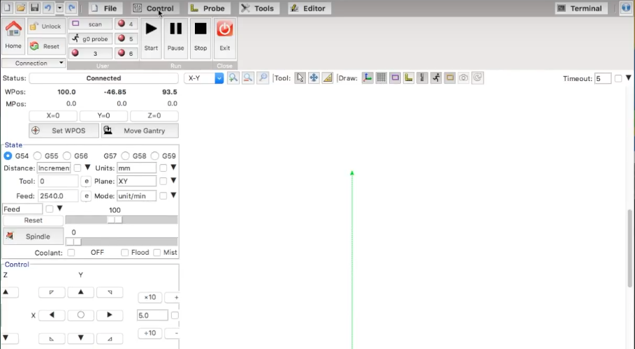
In the lower part we will find the arrows wich allow us to choose the direction of the movent in each axis.
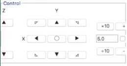
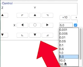
To the left there is a listbox where we can choose how many units each click will value, if your machine have no limit switch you have to be really carefull and choose right to not crash and cause any damage.
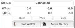
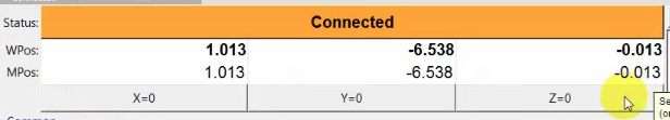
Bellow "status" we can see a relative position in each axis, this position is relative to the last cero set in each axis did by user
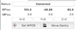
We can click on the button X=0 Y=0 Z=0 to make the actual posion the cero position, this potition it's not equivalent to the one stored in Home button, be careful with that
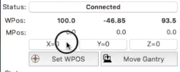
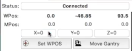
The position where is the point of interest to start milling is where we should cero the position on each axis so we can continue with the autolevel process.
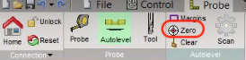
Autolevel
Before Starting this process is important to open the G-code file we want to mille on the top bar menu, go to file, then open and select the correct one go to Probe in the top menu and click on autolevel
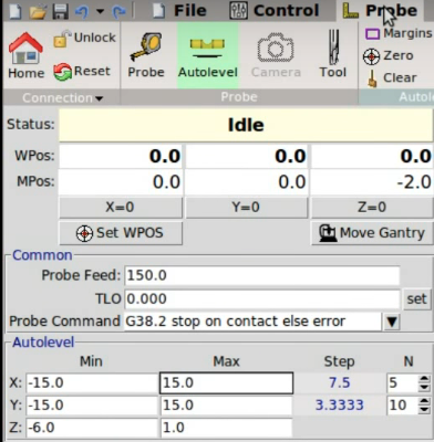
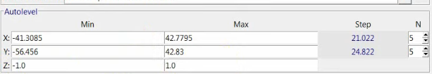
If you know the area of your milling space you can write it manually here, know that z parameters means how much the tool will go down and how much will go up to a safe distance. In this picture will down -1mm and up 1mm.
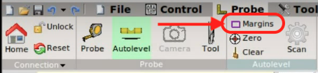
However I recomend to click on margins to make the programm select the area automatically, the you can choose the number of scans you want to make in that area, of course more points of scans makes better precision but takes more time to complete the scan, in the lab we use 7 scans and it's enough to have good results.
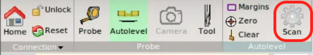
Then you can start the Scan process but be carefull. Note: To scan we have to use a sensor depending on the material you will work, if the material have good conductivity properties you can use a conductivity sensor, if not, you have to use a pressure sensor or similar. If you do the scan without a sensonsor or any probe tool the machine will crush against the material.
Now go to probe
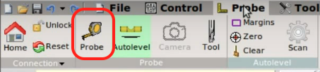
In Probe we will set the zero position of Z axis to ensure the depth of milling will be done with accuraccy.
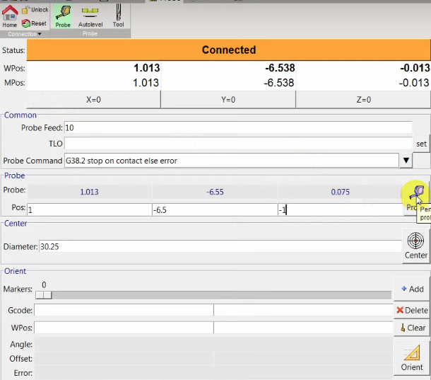
Once you click on the probe icon and the tool touch the material we have to make in this coordinate the zero of Z axis
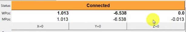
Now a very important step is go back to Autolel and press the Zero button, withoth this step the zero on Z axis will be wrong and the autolevel will have no sense then.
Things almost done, remove the sensor you are using, if your spindle turn on manually this is the time to do it and then on the top menu go to Control and click on Start. Now the machine should start milling well.
PHASE IV - TESTING
<You can find the result of our group on the machine page
See the final result!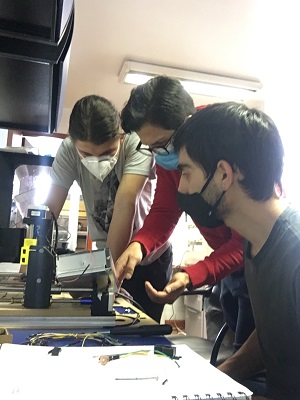
You can see the individual progress and contribution on our pages
EXTRA BONUS - TROUBLESHOOTING
Here you cans see the problems that we have and how we solve them.
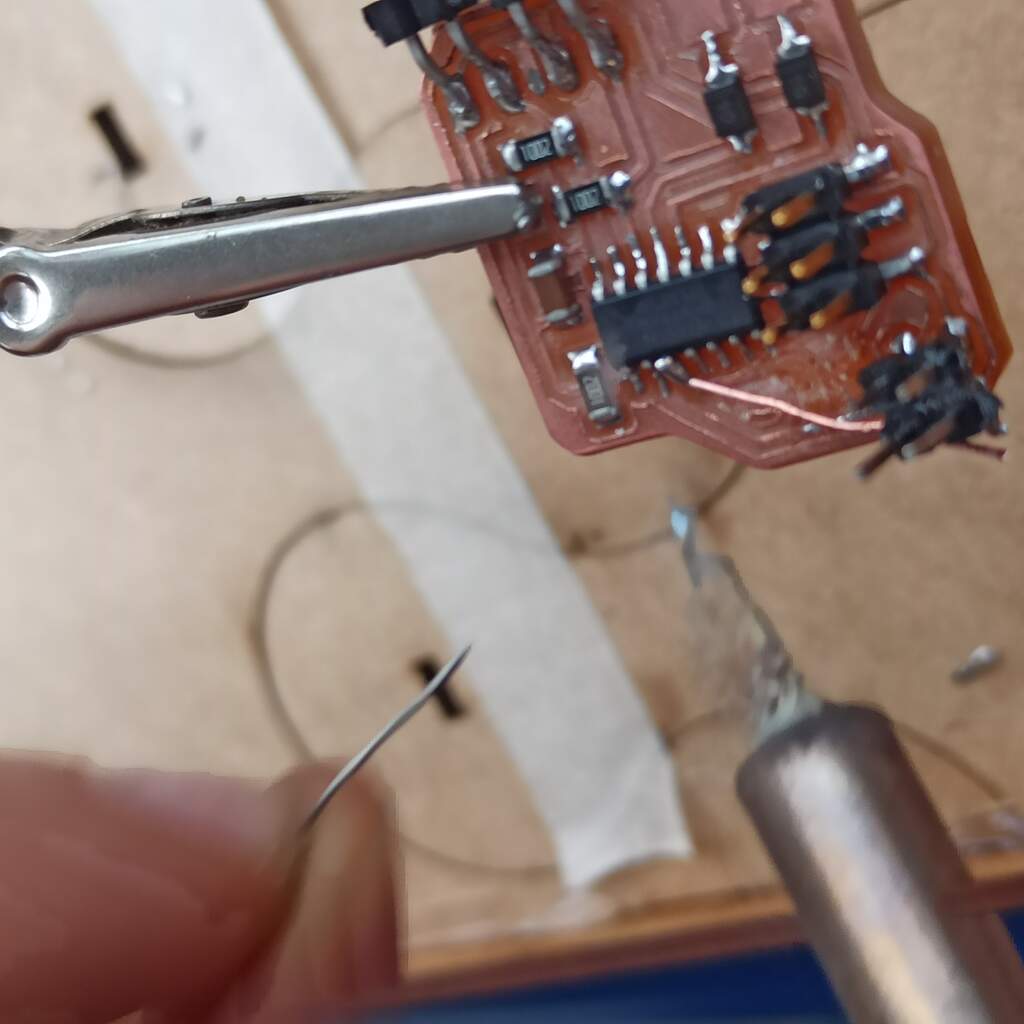
Broken pin on the circuit board
While programming and testing the board we have and inconvenience, one of the pin headers to connect the phototransistor broke, peeling off some traces. Luckily Camilo managed to solder the header again and using clear epoxi we secure everything on place again.