3D Scanning and Printing

3D Scanning

Is the process of capturing the geometry and sometimes texture of real-world objects and create a digital representation, then you can edit, render or print it using a 3D printer. Is useful in the video game industry to make realistic games, also the VR and AR fields use this technique. And can be used to measure and represent 3D spaces to make simulations or measurements, for example of archeological sites or caves. Has also application in the medical field.

There are various techniques to 3D scan, you can sense and measure the object from a lot of angles and calculate the geometry, emit a pulse of light and compute the result, this can be a laser, IR light, light, electrons, sound. You also can put the object inside a 3D scan that produces known lighting conditions and based on the reflection make the scan, this can get very accurate. There is also a way to use a physical probe to scan points on 3D space and reflect those on software.

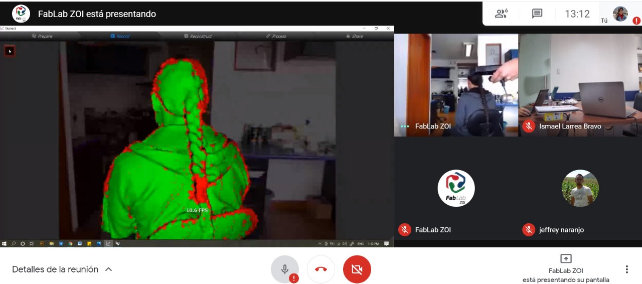
For this practice, we use a Kinect, a 3D sensor for the Xbox360 that can be used as a 3D scan when used with the software Skanect and scan ourselves on a spinning office chair, so the idea was to work on pairs, one scanning and the other as a model.

Scanning workflow

  1. Connect the Kinect to the computer and be sure that the program recognizes it.
  2. Prepare the area and set the scanning volume on the program to be sure the only object inside is the target to avoid noises.
  3. Press the record button and slowly spin the target, while moving the Kinect up and down trying to always frame the target in the center. This will help the software fill any holes.
  4. Turn the target for two revolutions to ensure that the software has enough data and can fill any blank spaces, you can visualize that in the viewport while scanning.
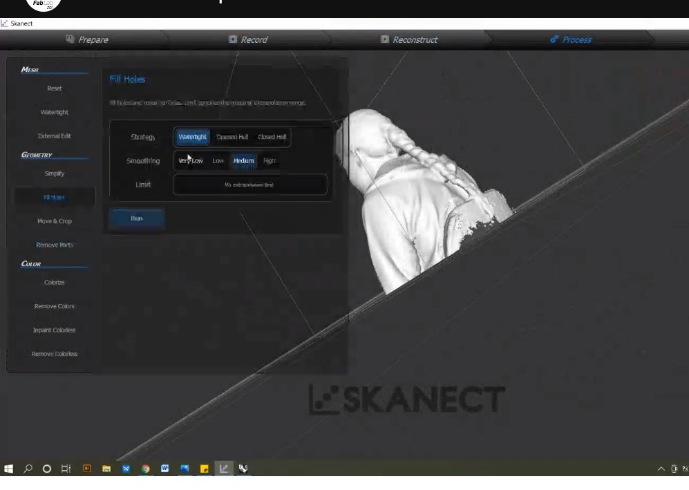
  5. Stop the recording and wait while it processes the data, you can verify if the scan was successful and also clean up some of the noise objects that can be around the model.
  6. And finally you can export it as .OBJ or share it.
3D scanning process 3D scanning process

Scanned object post-processing

As the scanning process isn't perfect you should always clean up the mesh and fill some holes. In the Skanect software, we try to apply the auto-fix holes function but it just gives the model a thickness with a hole going from the head to the bottom.

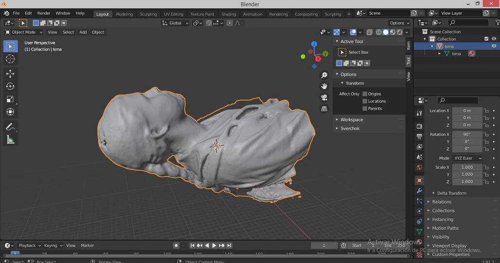
So I decided to use Blender to manipulate the mesh and fix it. I import the .OBJ file and scaled it down,then I started to clean the inner faces and fill the holes, this process takes a while but when I finally close the mesh.

I could switch to the sculpting mode and enable dyntopo a function that creates or eliminate geometry as needed and sculpt the mesh.

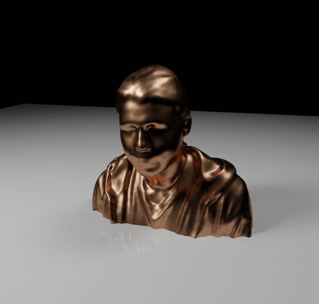
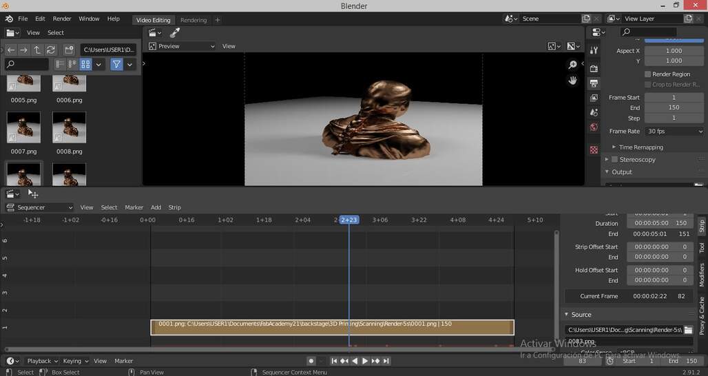
Using the smooth and inflate tools I fill some of the holes and fixing my jow. Then I set material with metallic properties and reddish color to imitate and sculpture. I set a plane as ground and make it reflective. I render a frame using Eevee the built-in real-time renderer. Then I set a short animation to be rendered with a 360 loop around the scanned object. And use blender to edit the video and add some text.

.obj imported on blender test frame rendered video editing on blender
Get the .stl file ready to print

3D Printing

This is the process of fabricating objects by adding material to create the final shape, is called additive fabrication. It can be made by different techniques, the most accessible is FDM (Fused Deposition Modelling), SLA (Stereolithography), SLS (Selective Laser Sintering) and much more, a really good explanation of each one and how to design considering the limitations and strengths of each technique can be found on this page.

Design considerations to 3D printing

You have to consider some key aspects to design things that will be 3D printed, sometimes in order to 3D print some features you have to use supports but this can waste material, so is always better to avoid the use of supports. Find the best position considering the layers and how it will affect the final object strength.

You can use this next table as reference:

Table of references and design rules to 3D printing

This table summarizes the different design rules for each additive technology as long explained on this page. This image was taken from Robin Brockotter blog.


Group Assignment

This week we have to figure out our lab 3D print machines capabilities and limitations, as well as the basic workflow to use each printer.

Check out our page!
Our first 3D stress test


My design for 3D printing

working on fusion 360

I use fusion 360 to create a parametric design of a walking cube. That will be printed on one piece and then be able to hopefully unfold and extend some 'legs', the key parameter here is the clearance between pieces to obtain mobility in the joints and legs.

The complicated part of this design was the hinges, I first intended to use a cylinder, but Robert advice me to apply an angle and make cones to avoid the need for support material while printing.

Folded cube Unfolded cube
Fusion 360 file of the walking cube .stl file

Printing

After some explanation about how to use the 3D printers we start to print, I use just a half of the model to reduce printing time while testing, the tests, and results of printing with PLA are shown in the table below.

Test Speed Infill Layer Height Line Width Temperature
Half 66 mm/s 10% 0.3 mm 0.4 mm 200 °C
Complete 55 mm/s 20% 0.2 mm 0.4 mm 200 °C
Note: on both printings no supports were used
Print preview with supports Print preview with out supports

Even though the Cura software was creating supports for some parts that have overhangs greater than 45°, they were very small areas and building supports will not improve a lot and make more difficult unfolding of the cube, and also require more cleaning.

Results

The first print was printed on the Ultimaker 3 and was a success, the printing quality wasn't the best, some rough lines were visible on the side faces but the mechanism was working pretty well, the hinges are a bit too lose, but the idea works and it folds and unfolds correctly.

second try folded

For the second attempt, I was planning on fixing some of the issues with the printing and pushing the limits on the hinges to get a more tight joint. But the extruder nozzle got obstructed and my time in the lab was also ending, so I let the G-code be printed on the Prusa i3 when it finished the group test. This came out looking pretty well but when was time for unfolding the hinges were soldered together, and when trying to open it broke, but I manage to understand where the problem was by breaking everything and see the merged spots on the hinges. Sadly it was all the inner circumference so it was pretty hard to break or separate.

End result, v 0.3 printing soon...

folded leg unfloded folded leg
standing folded leg closed complete model leg  broke model

Finally! it works!

Screenshot of Fusion 360 focused on the problem

As discovered before the problem was on the hinges, but on the CAD file. I initially set up my sketches for a cylindrical book hinge. But later I use a fillet to make a cone hinge and facilitate printing without supports

But I didn't take into account trigonometry... as the parallel lines now have an angle with the original sketch plane the distance (0.6)mm on the sketch was not the real distance of the surfaces, so they weld when printing. To fix it I divide the distance by the sin function of the new angle (45).

Walking cube on my hands Walking cube animation
closed walking cube standing walking cube upside down walking cube

Conclusions

This week was pretty fun, having the idea for a design that meets the requisites is a challenge but I reuse an old idea, that is simple but yet very interesting for me. Making a simpler model that can be printed was a challenge but is a pleasing experience to bring my digital creation to something more tangible.

The 3D scan was also a new experience, editing your own jaw and fixing holes on a 3D model of myself was fun and the end result even is not 3D printing I think came out pretty well.

Have I?


Prev Next