Week
Six
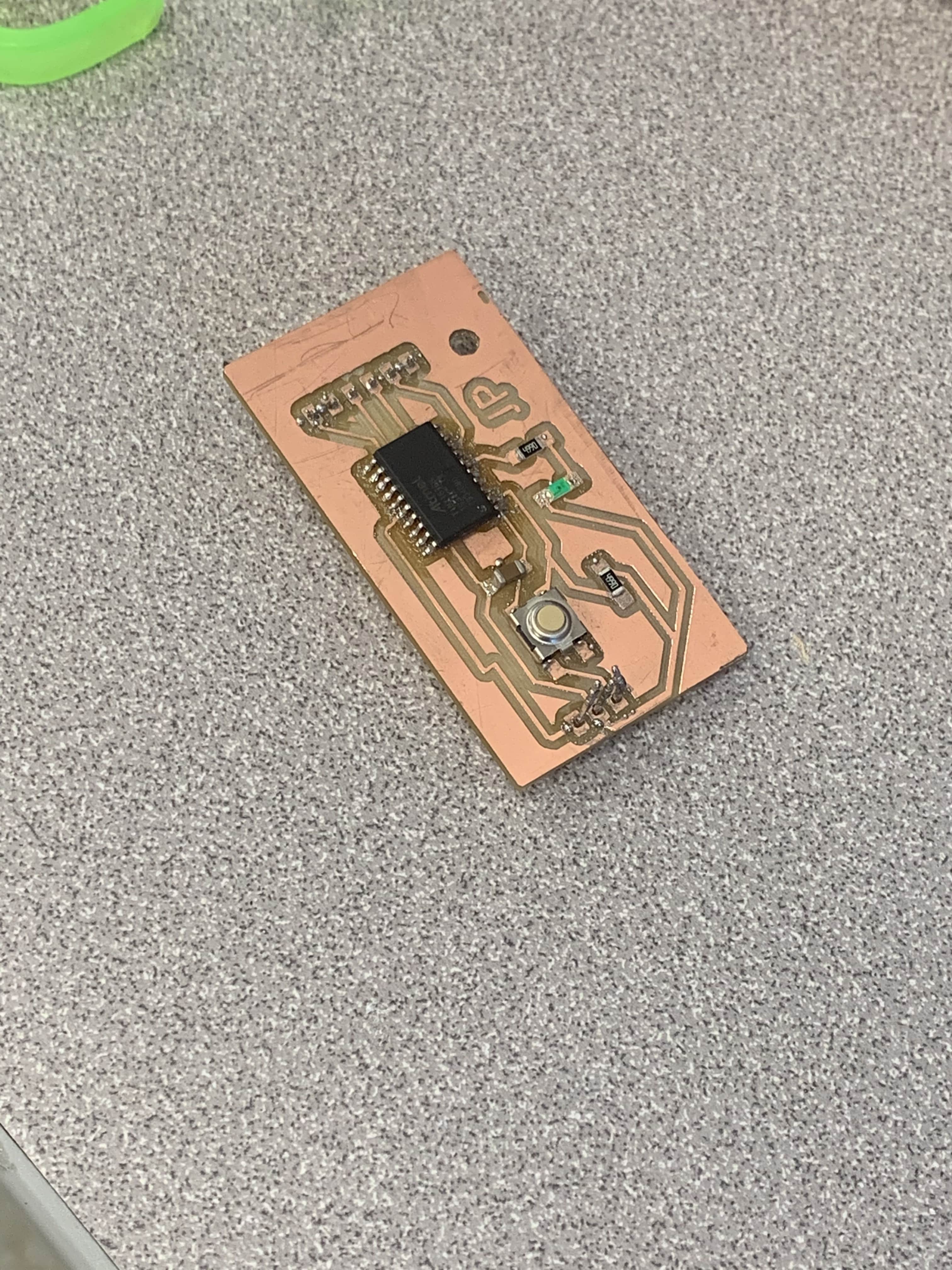
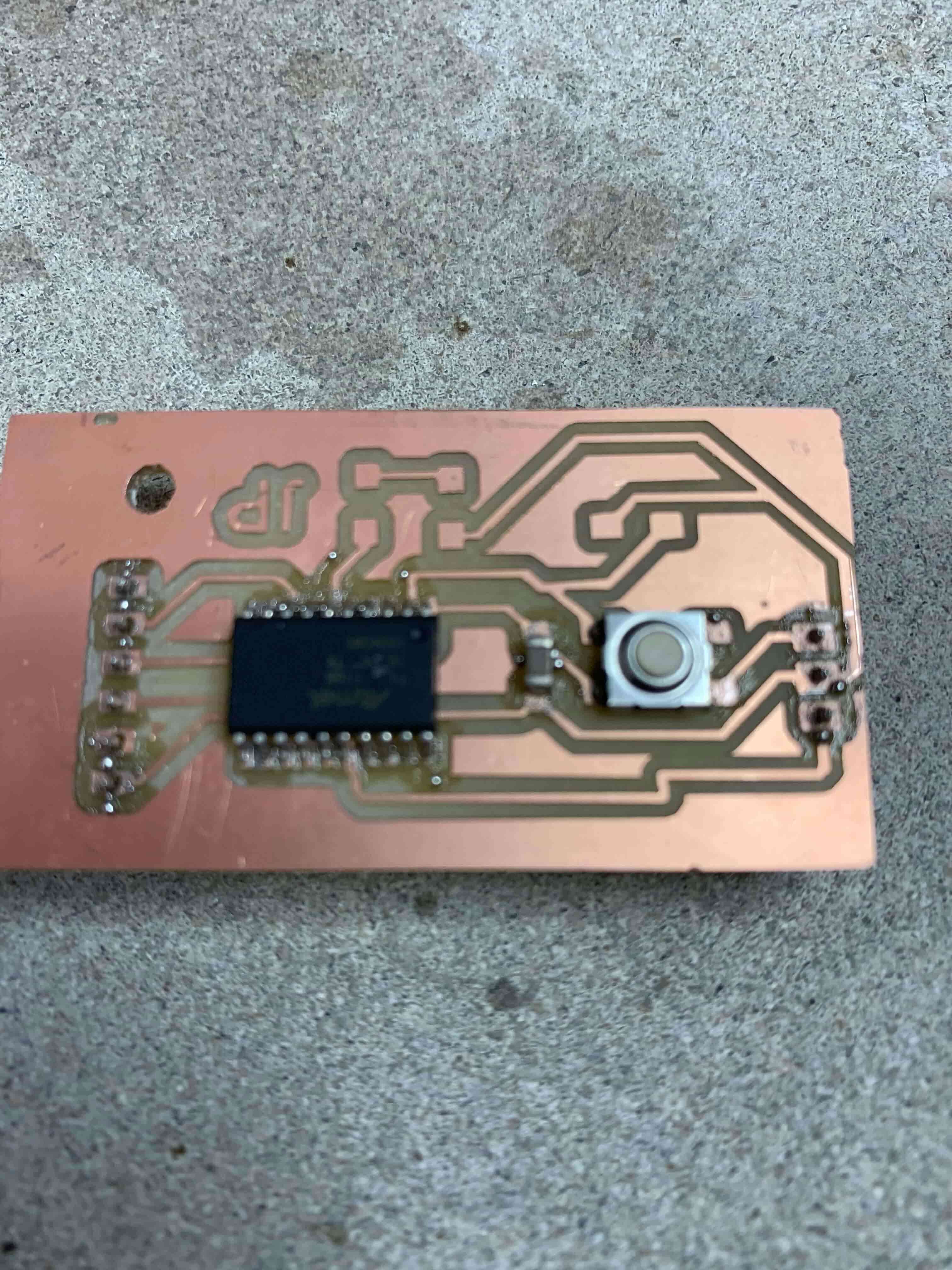
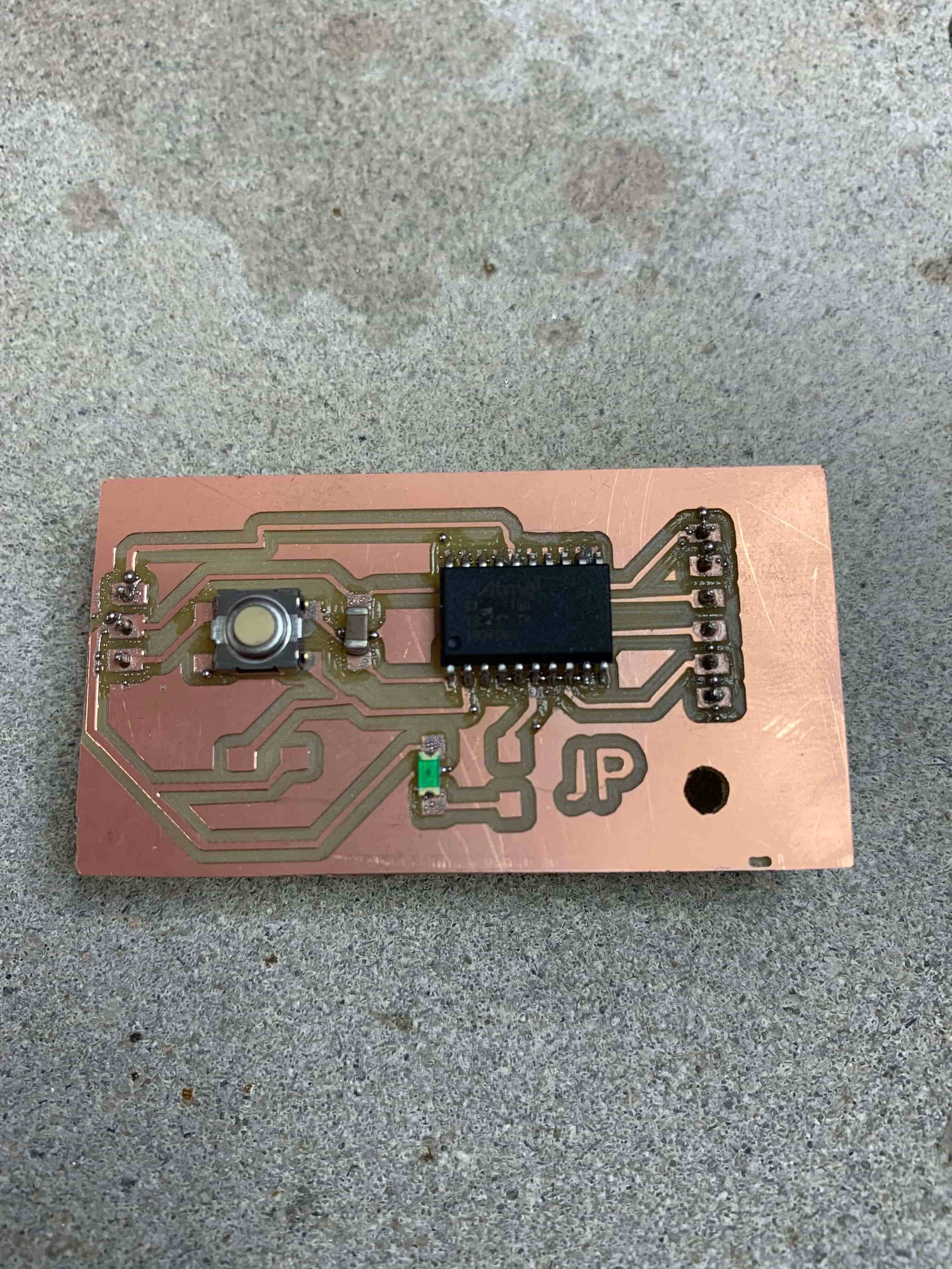
Customized Board
Group Project
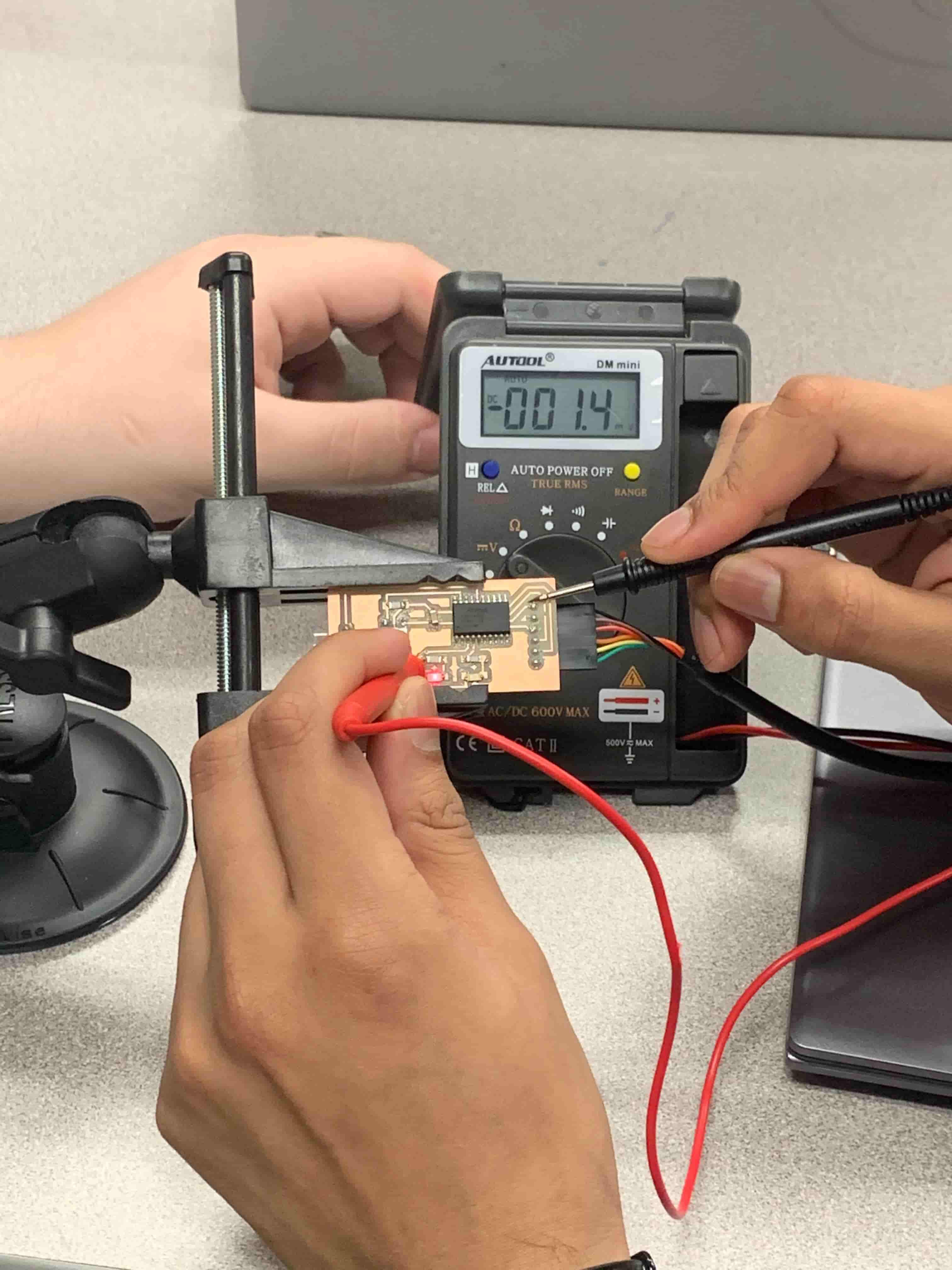
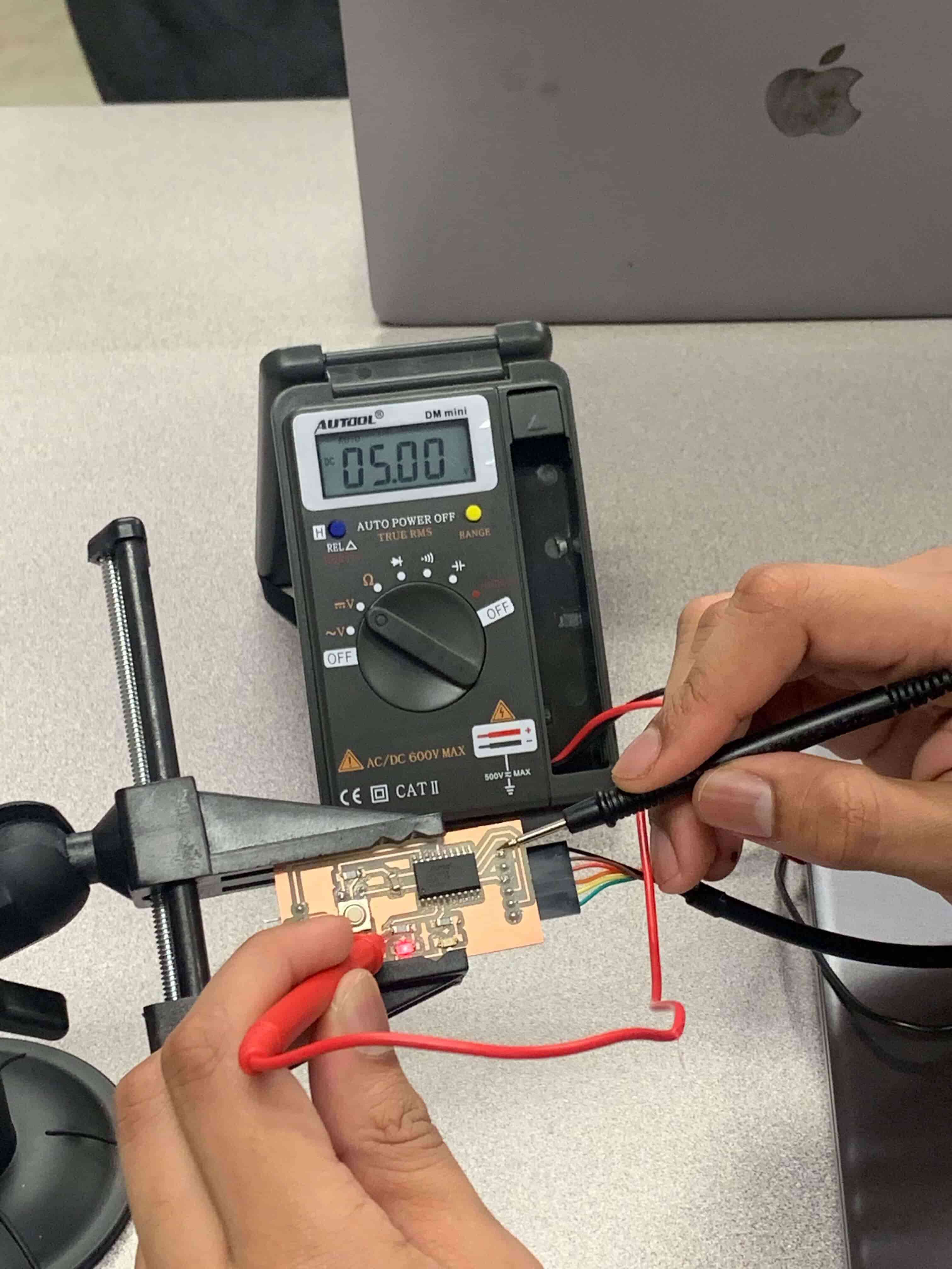
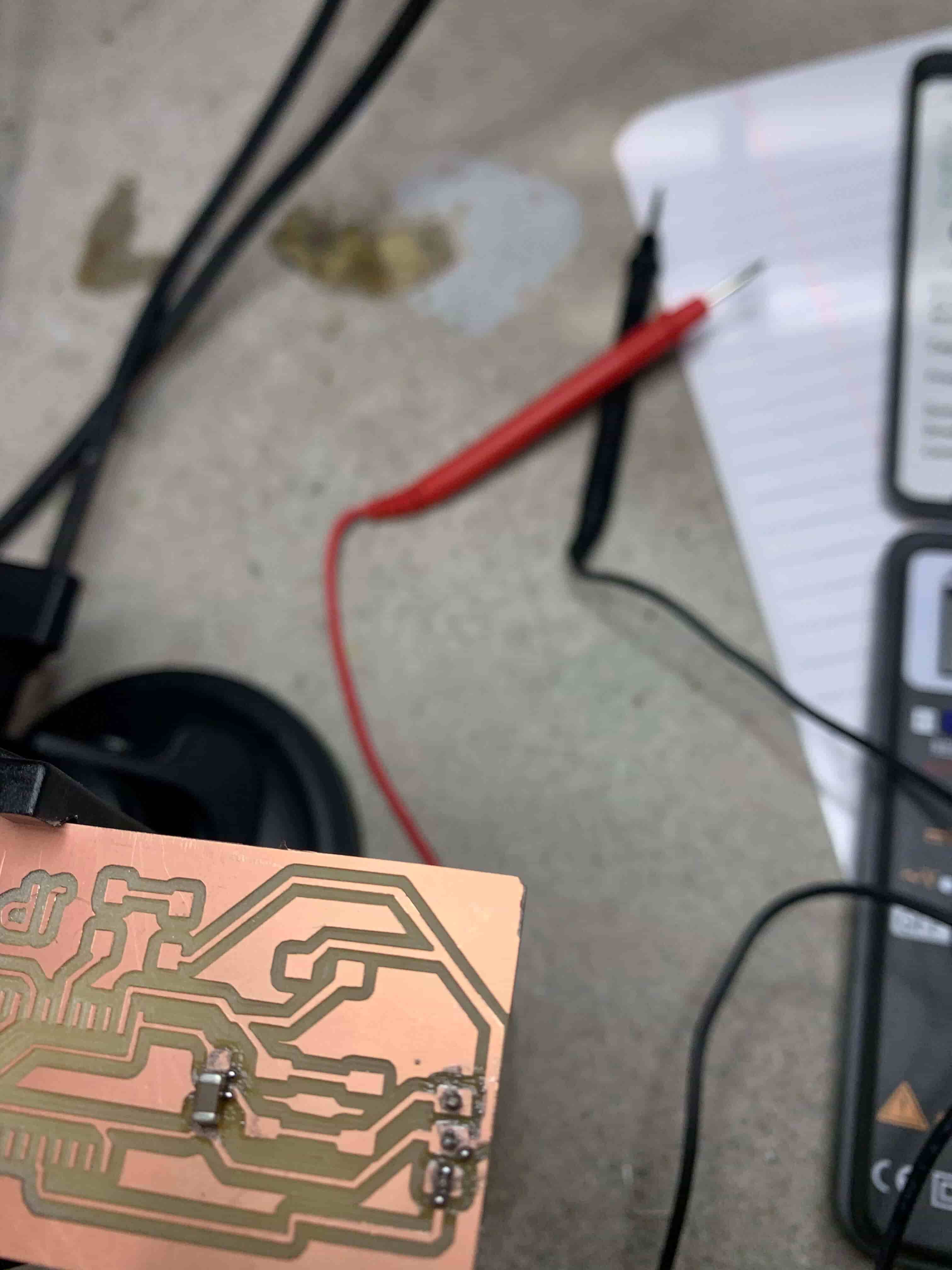
This week’s group project was to become familiar with the capabilities of the multimeters in the lab as well as the oscilloscope we have. The reason that we had to do this, is pretty straightforward, you can't see the electricity on the board. So having these tools available to us is incredibly important so that we can accurately troubleshoot problems in our boards. So with the multimeter, we did some voltage measurements. In doing these measurements we could see how voltage drops over resistors, and we could see that with a button there is no voltage when the button isn’t pressed, and then the voltage flows freely when the button is held down.
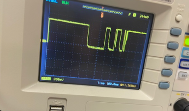
Next, we used an oscilloscope to look at voltage noise. What I mean by voltage noise is that using the oscilloscope we could see the ones and zeros the computer was sending as voltage surges. We could do this because the oscilloscope measures electrical signals at a much higher frequency than a multimeter does. This allows for us the users to notice things that are impossible to notice with a multimeter but still may cause problems.
Intro To Individual Assignment
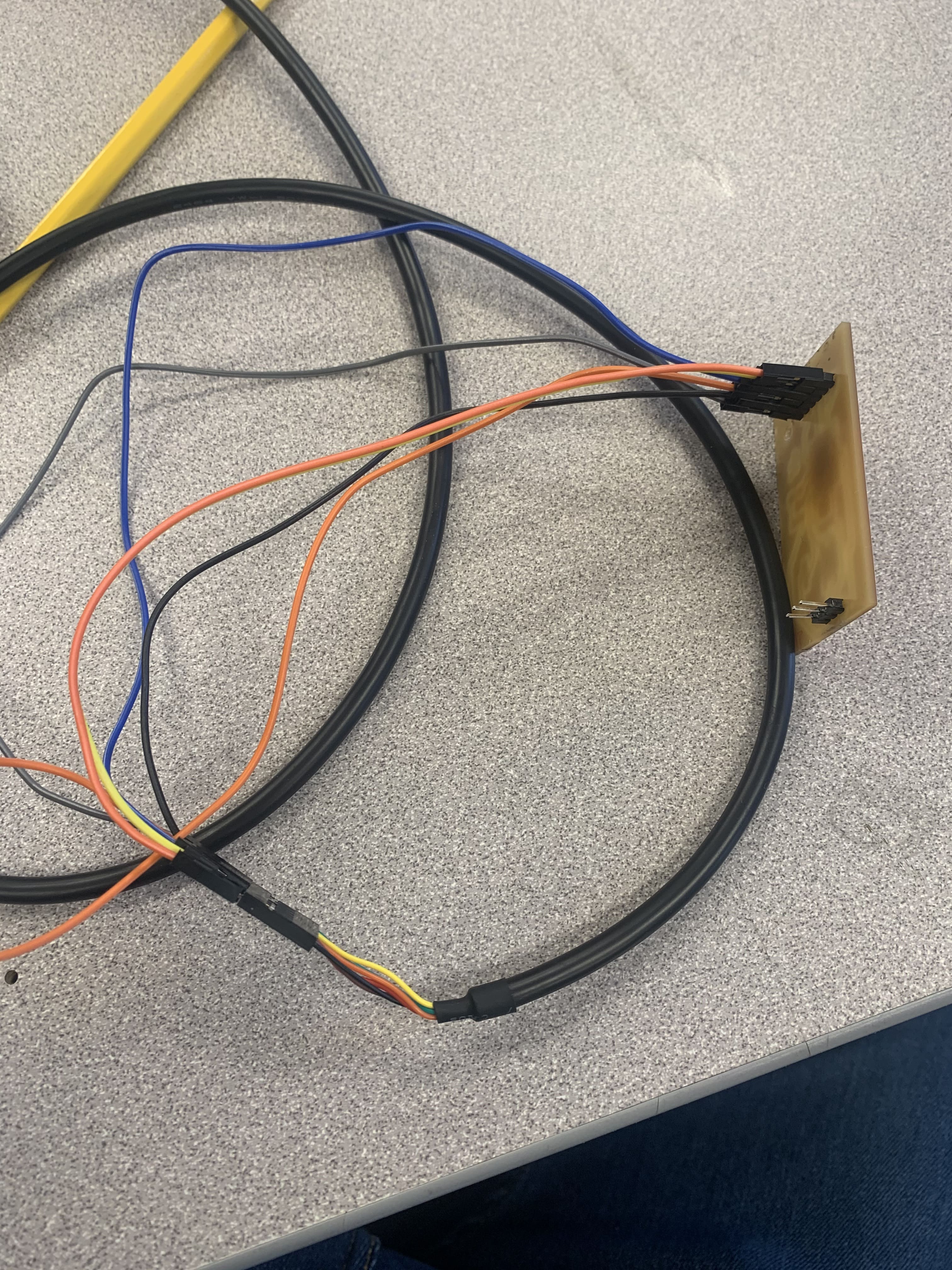
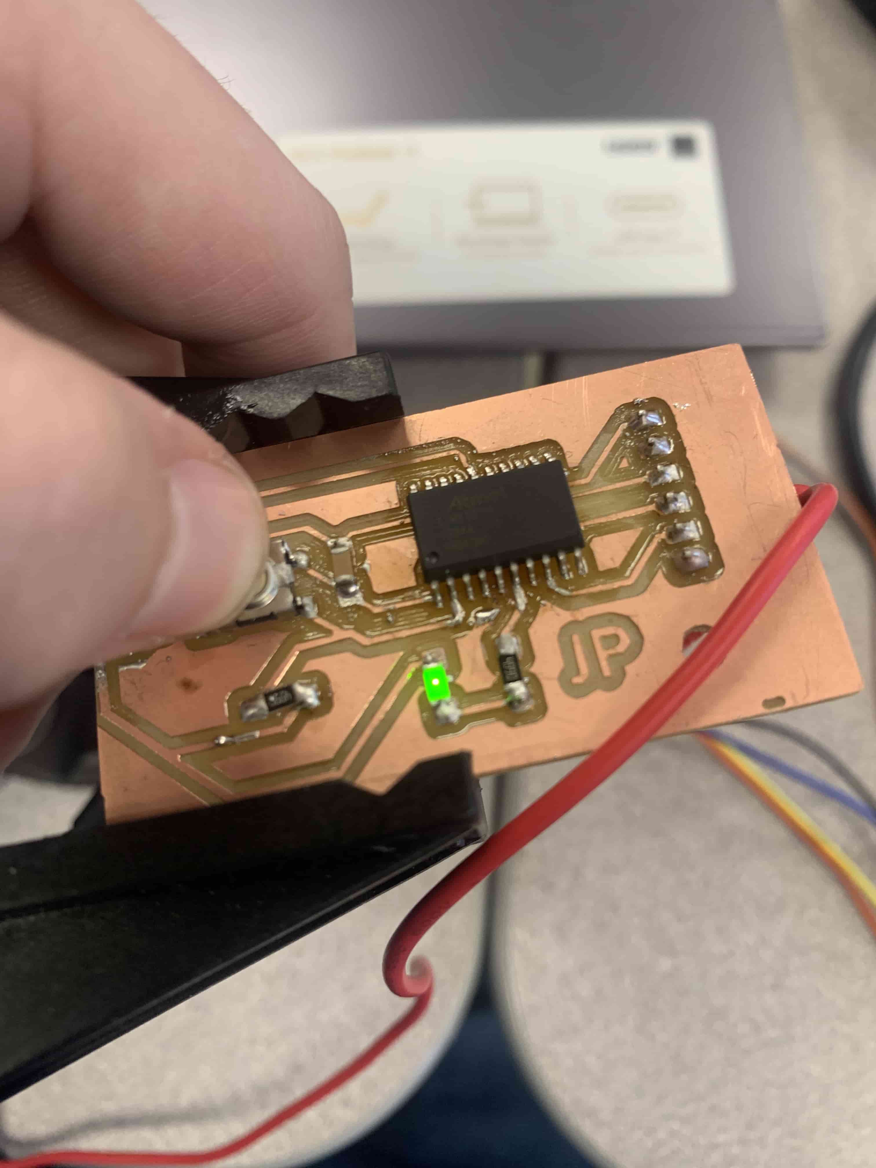
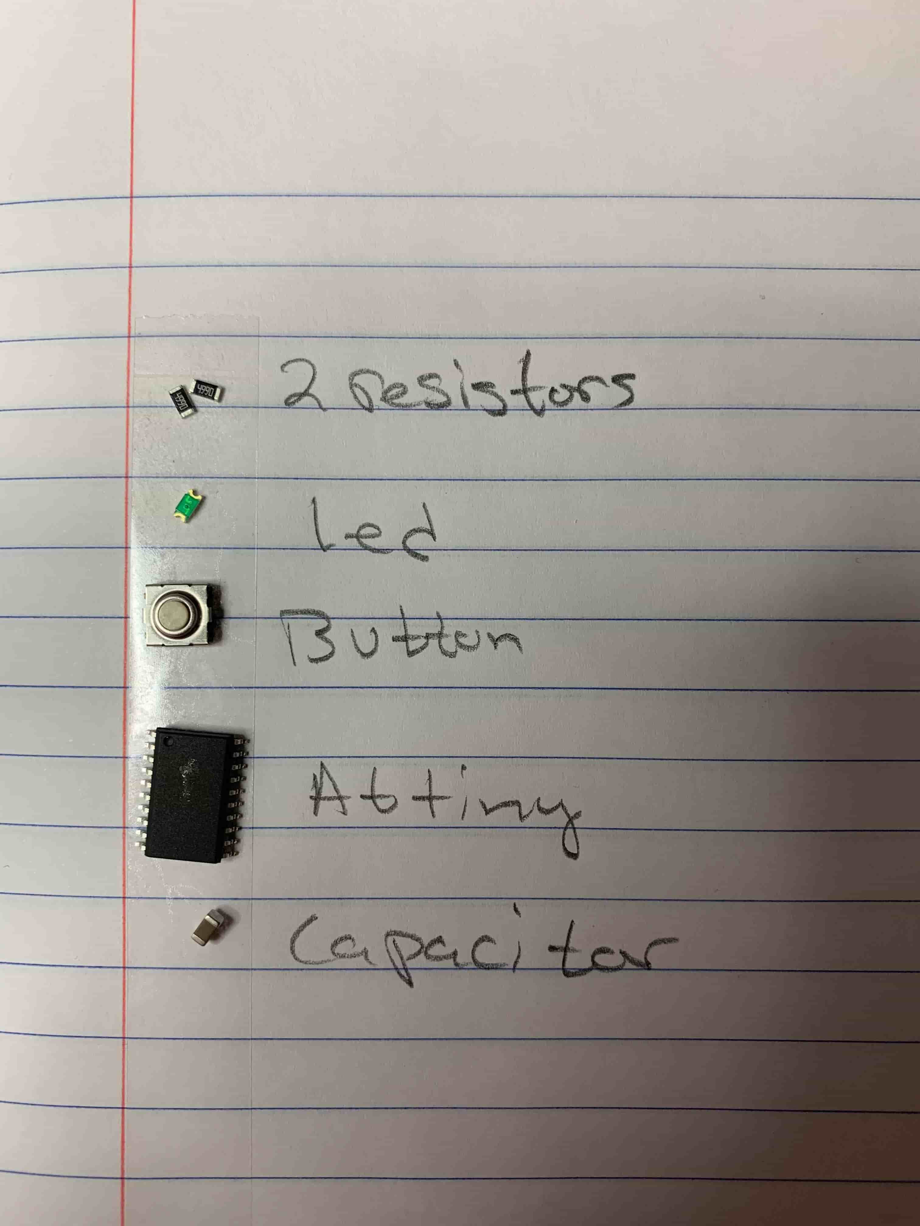
The end goal of this week’s assignment is to have a board that we can plug into a computer using a cord, and when you press a button on it, a LED turns on. Originally going through this week I wasn’t successful, and it took me quite a while to figure out what went wrong. With that being the case I will walk you through an overview of my process now, and I will break down all of the places where I failed spectacularly. I will have download files for the board I printed and the code I wrote at the bottom of this page.
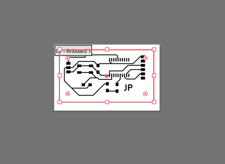
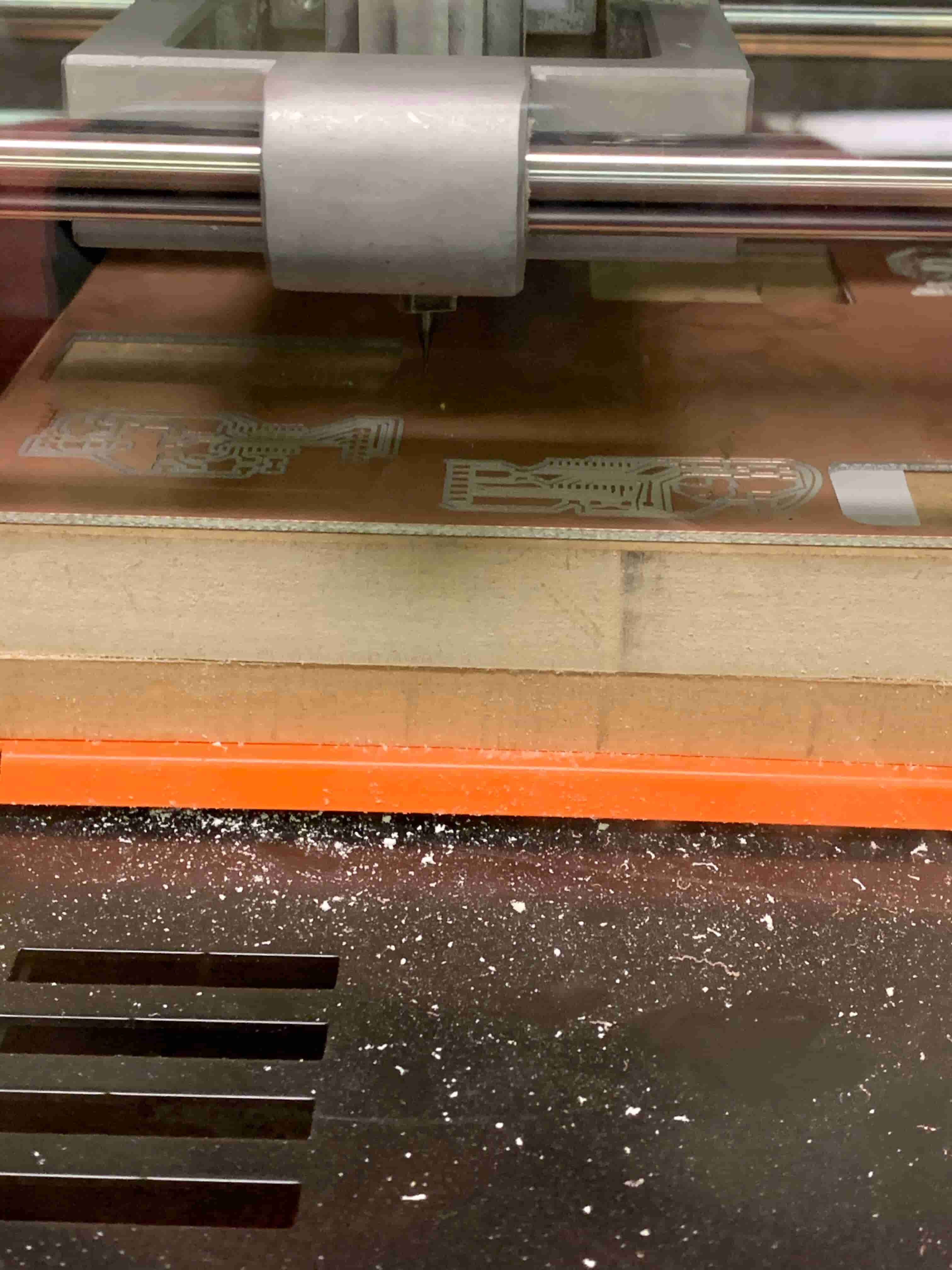
The first step of this process is designing the board in KiCad. Following this step, you need to take your .svg files into an image editing software to make it so that you can have functioning outlines and holes drilled for your through-hole parts. With the .pngs that you get from your image editing software, you can now start with mods. You can place each file into mods. Mods will give you .rml files that you can then bring over to your Roland mill. Now you can put it into Vpanel (not Vcarve) and carve out your board. With your newly carved board, your next step is to start soldering. Once all of your parts are soldered you're nearing the finish line! Now you can upload the hello echo code that you can get from FabAcademy, just to see that your board works. Then you can write a bit of code to make your board turn on the LED as you want it to, and upload that. Now you are done! That's so simple when everything is written out. I think I ran into trouble at nearly every step of this process.
KiCad
This is probably the step where the problems I faced were most easily overcome. My main problem here was my lack of puzzling skills, so I struggled positioning all of the parts so that the traces would work. This problem was overcome through sheer willpower, I just kept at it for a couple of hours until I was able to figure out how to make everything work. The other speed bump I hit was my inexperience in dealing with electronics. Just in case you didn't know having half an idea is so much worse than being clueless. I know just enough about electronics to feel that I don't need to look up any tutorials, of course, I can make a button start an LED... I was wrong. In a way. What happened was that a fellow student named Tuna looked over my circuit and noticed that my RX was connected to my TX and vice versa and he was kind enough to point that out to me… as an error. Now you reading this know, or will now learn that, that is how it supposed to be, they are supposed to be going into one another. This tiny mistake is what lead to my problem when I initially finished this assignment because all of the connections were good and the parts worked properly it was just this little mismatch. Luckily this isn’t a big deal it just means that I needed to swap my wires when coding this section. I’ll have photos of this at the bottom of the page with a big update section.
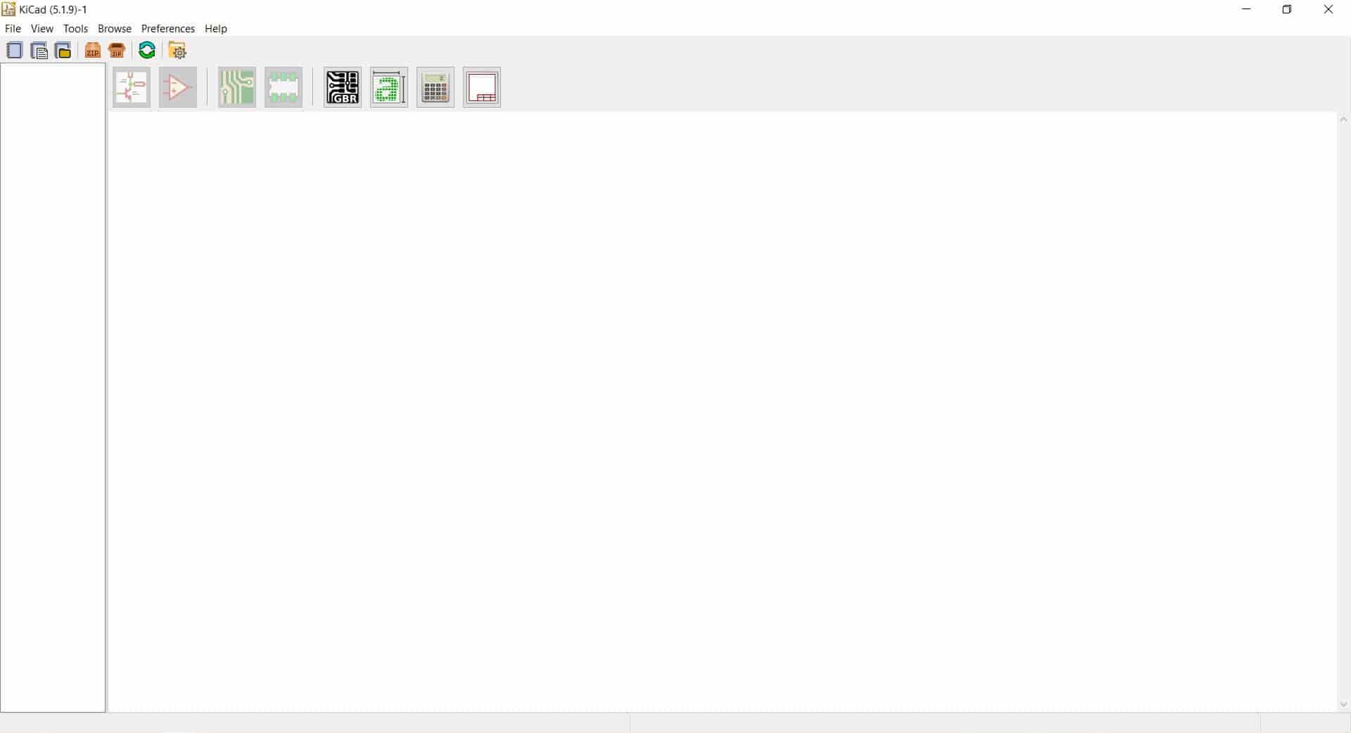
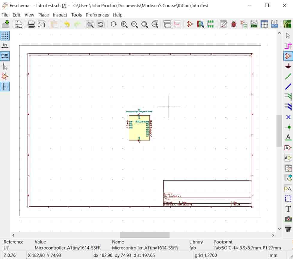
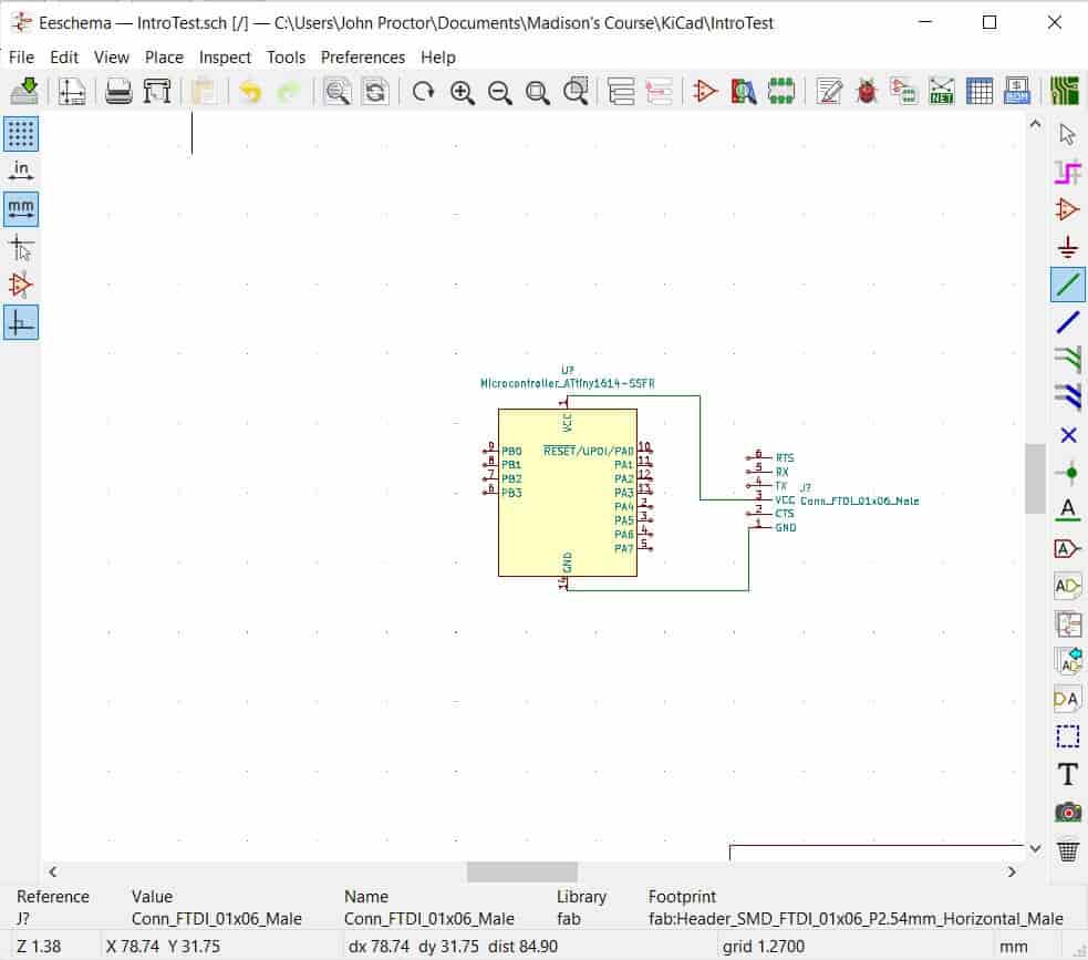
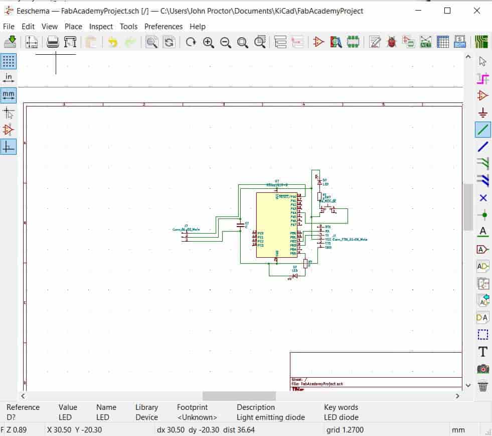
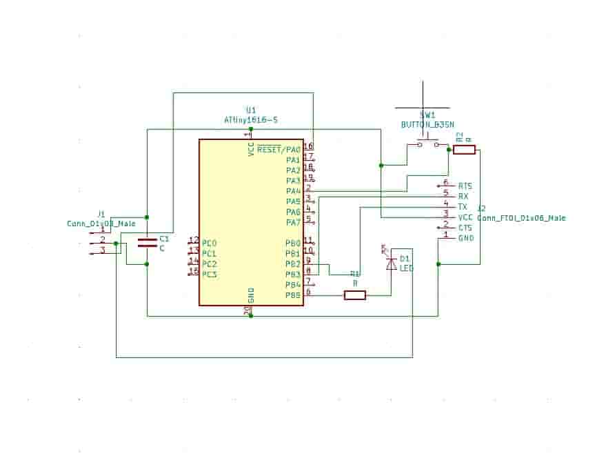
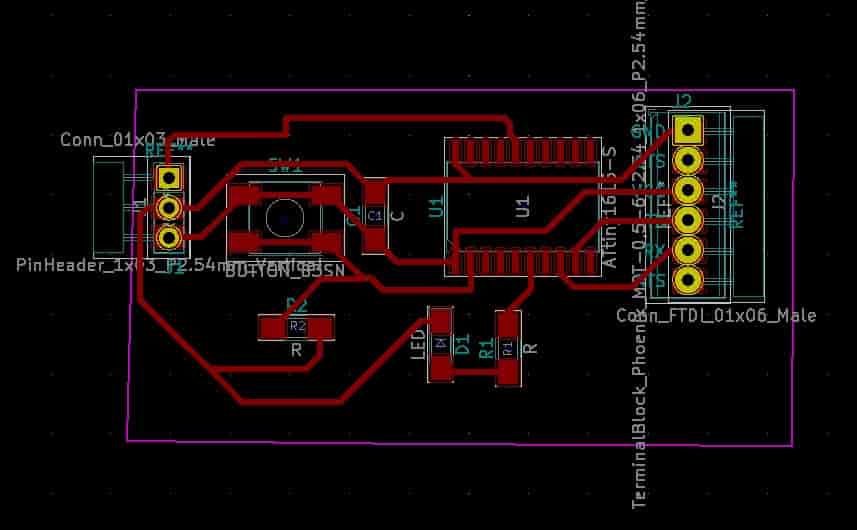
Image Editing
Going into this process I had the highfalutin idea that I could make do without doing the image editing step by simply using surface mounted parts. However, I was shortly informed that we didn't have any surface-mounted connectors. Doing this process was relatively simple you just need to separate the drill holes from the traces. Once they are separated you create a white square send it to the back, and you should have black holes where you need to drill holes and white everywhere else. Then you can separate all of your other parts into their layers so you can output .pngs of traces, outlines, and holes.
Mods
This step was one of the rare parts of this venture that I didn't have a whole lot of problems with. So long as I sent in good .pngs then it outputs good .rmls. This was just a matter of picking the right server program and changing it slightly so that the final step is to download the .rml file as opposed to operating the mill.
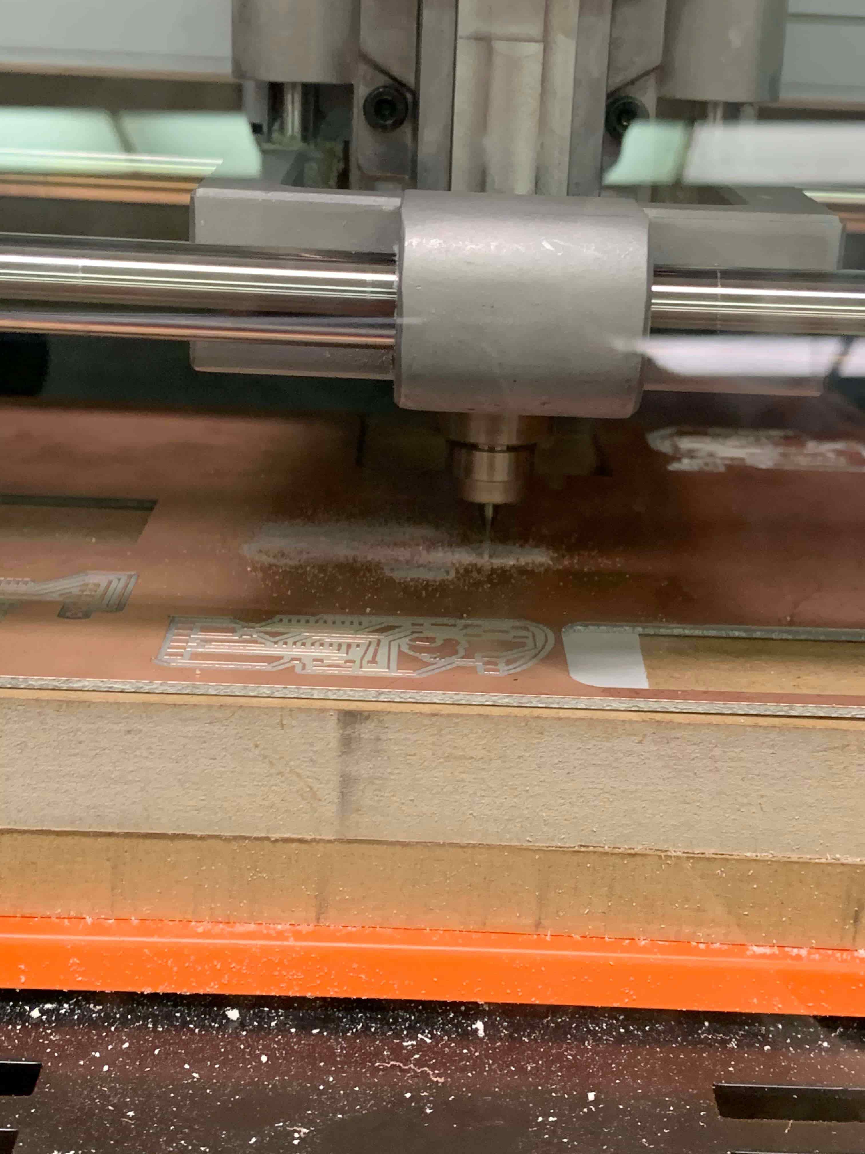
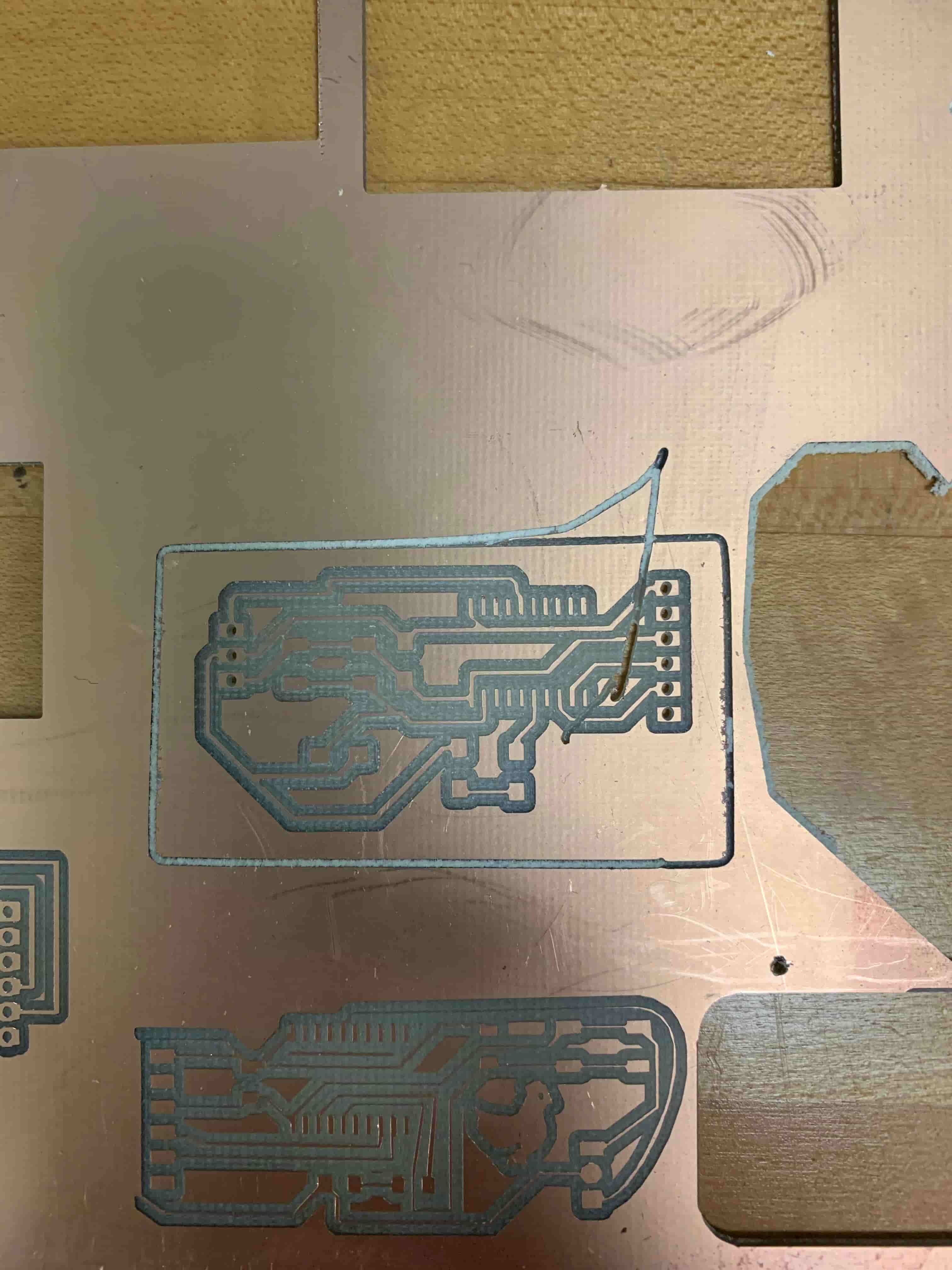
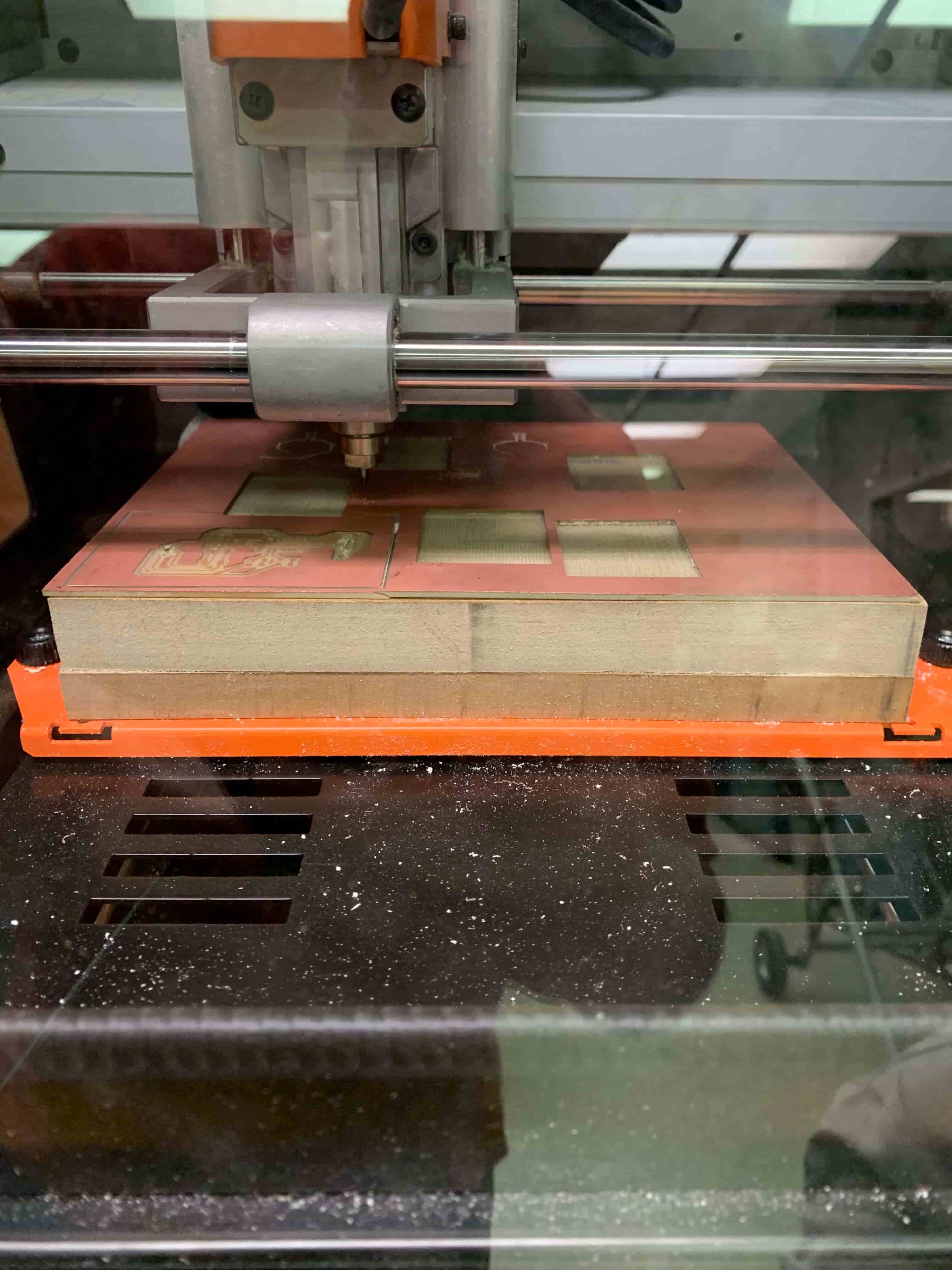
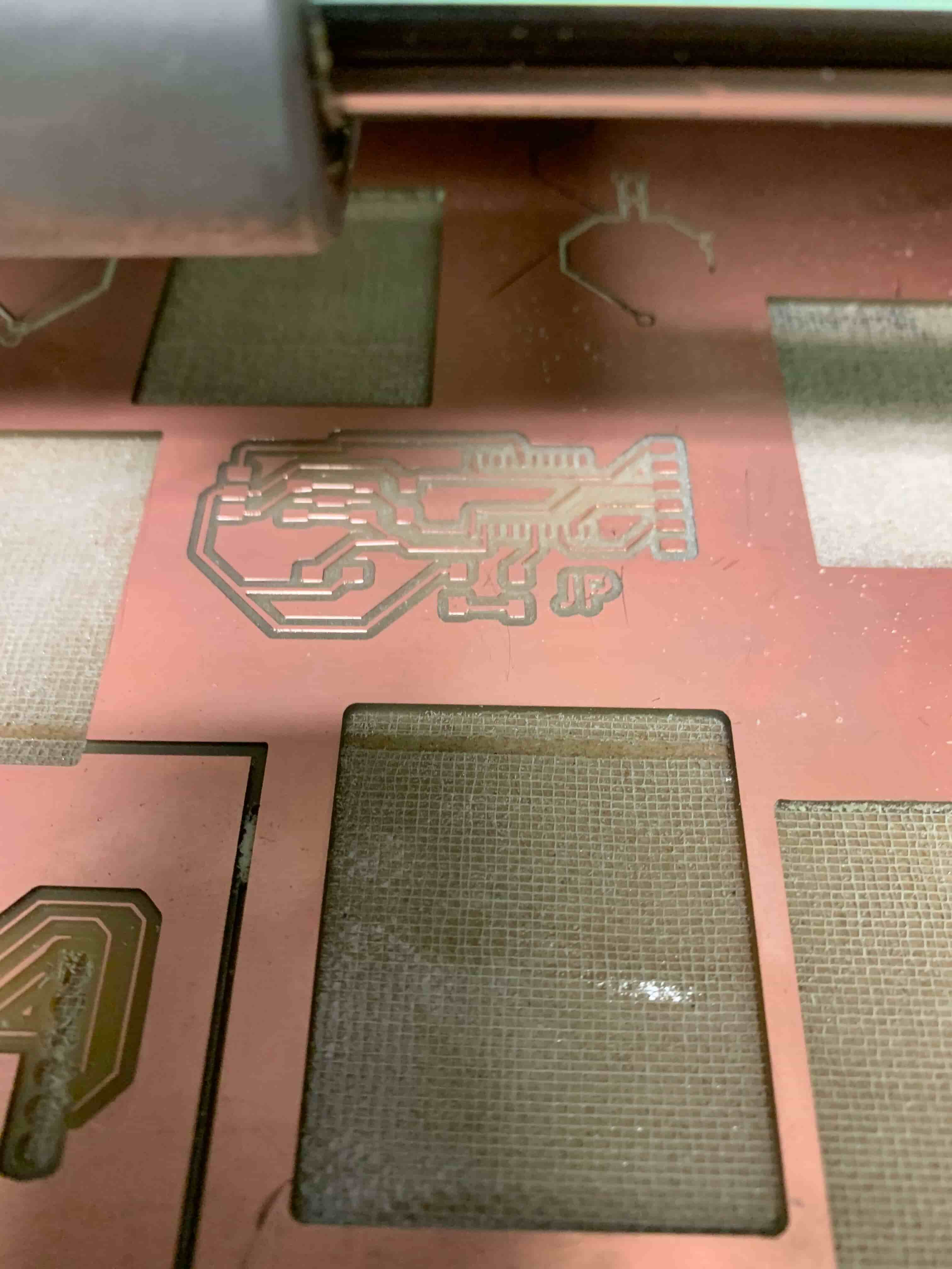
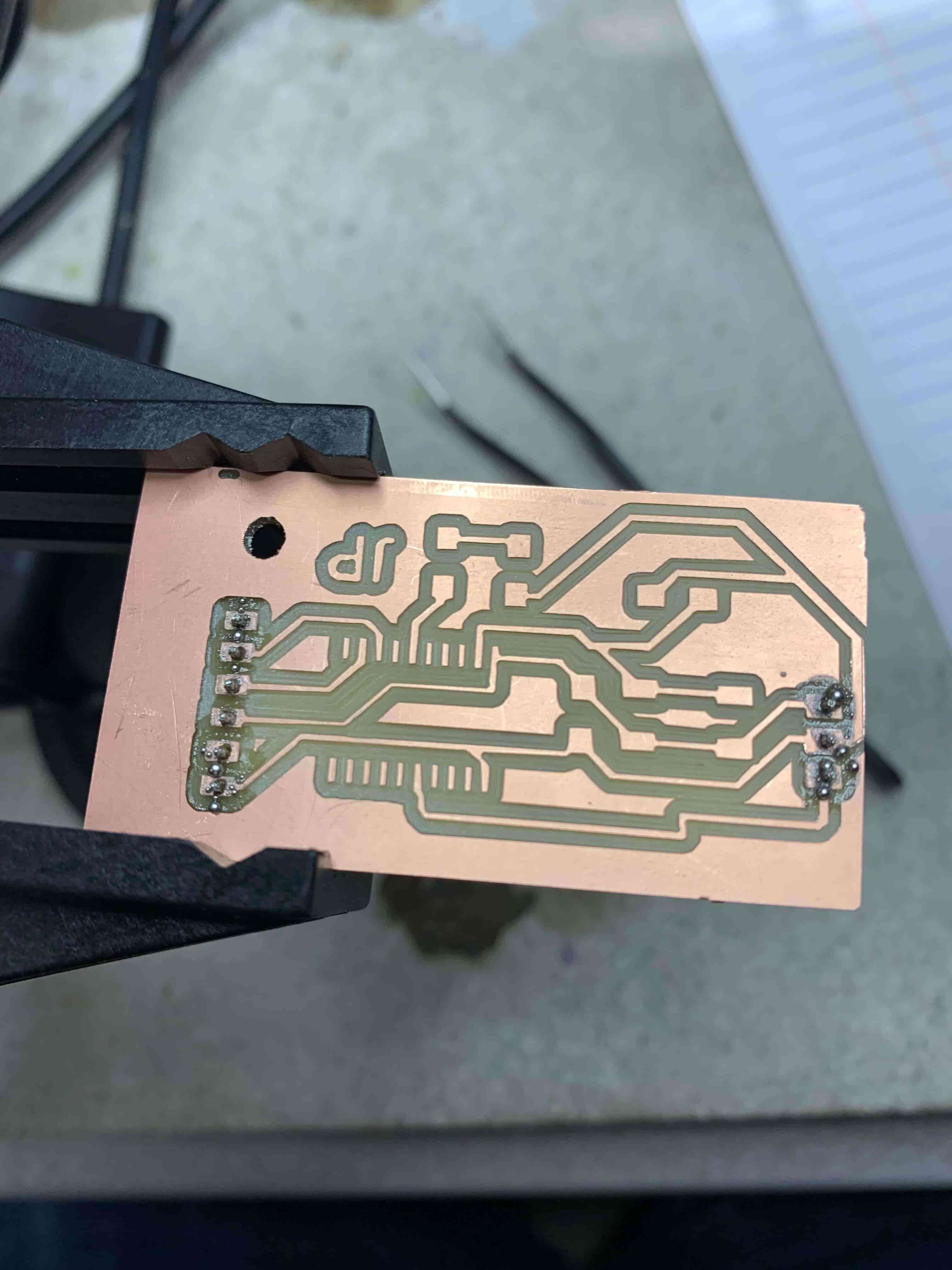
Carving
My nemesis is the Roland Mini Mill. If it wasn't for the exorbitant price tag I would take it from the shop and bury it in a shallow grave in the woods. However, that isn't an option and I need to mill a board so here I am. I had two main failures, that calmer heads would inform me had nothing to do with the mill its self. However, those calmer heads aren't here so I am going to attribute both of these instances to the malicious spirit living in the mill. The first instance was earlier on in my slow decline to madness. I had all of my files working and looking nice. I had the Z set well. Gosh, I even have the traces, and holes milled. However, when I went to cut the outline it quickly became apparent that whoever put the board I was cutting, onto the machine, didn't properly tape the board down. This cause the whole board to spin and the drill bit to drill right into my board ruining it.
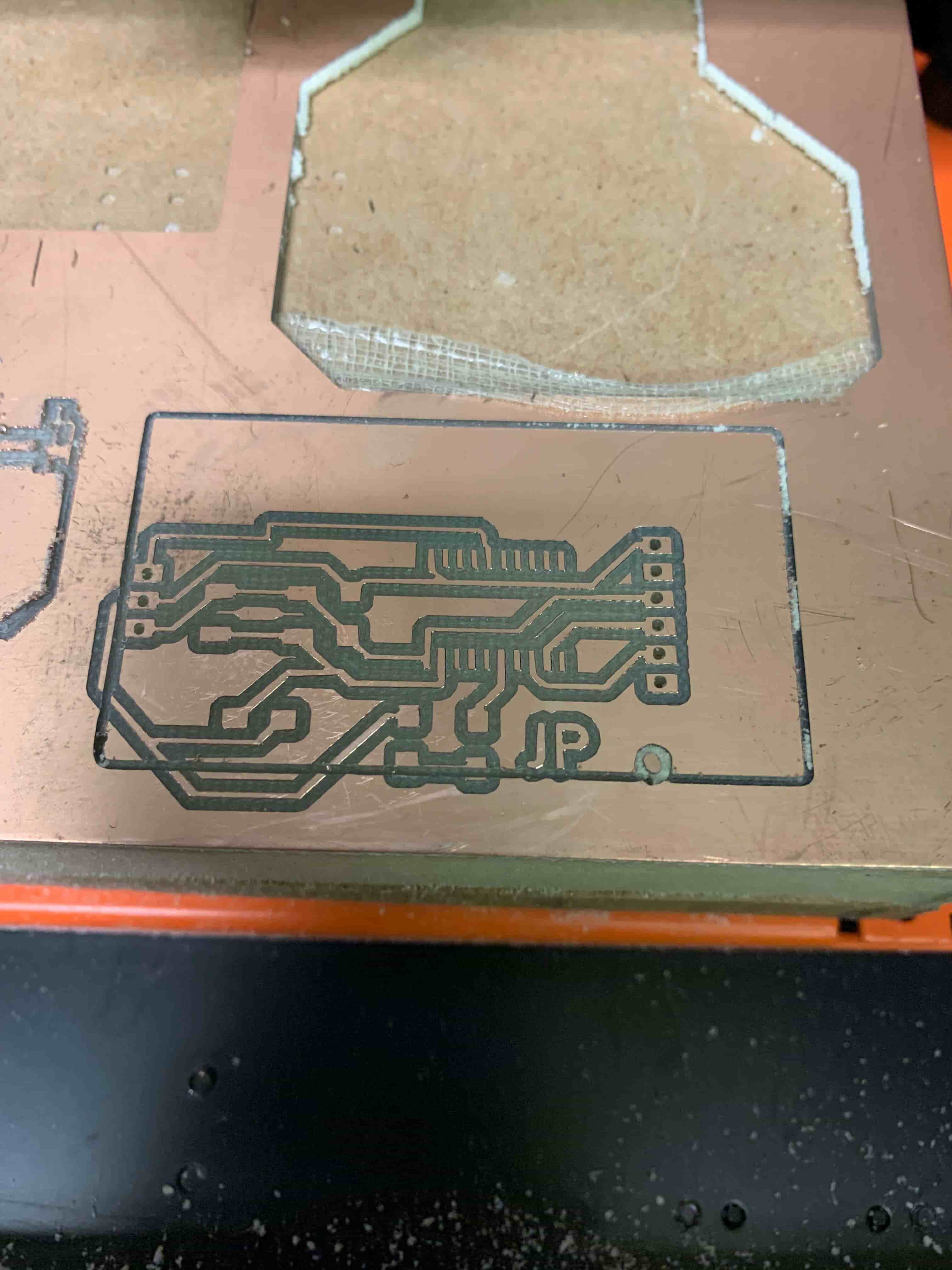
The second error came later along the line. It was just the next chance I could use the mill. This time I had to redesign my outline because there was less board left to cut from in the whole shop so the stakes were high. This time like the time before I had the traces done, the holes drilled all I needed to do was go over to the computer to grab the outline file. I should note that I was perhaps foolishly using a general lab computer for this purpose. When I discover that the demon living inside the mill manifested (really it was just another student by accident) and deleted the entire set of files that I had in Illustrator. Now you being a reasonable person who is like a hair more intelligent than I am, are probably thinking well you have the traces just create another outline! Wow, that is a good idea. I did have it I just didn't quite nail the execution. I super didn't nail it and the outline cut into the traces, and that was a shame.
I did eventually get this board milled with only a lot of tears, and to be honest I would struggle to even call this a learning experience. It was much more an assault on my patience and a test of my willingness to maintain basic human norms under pressure.
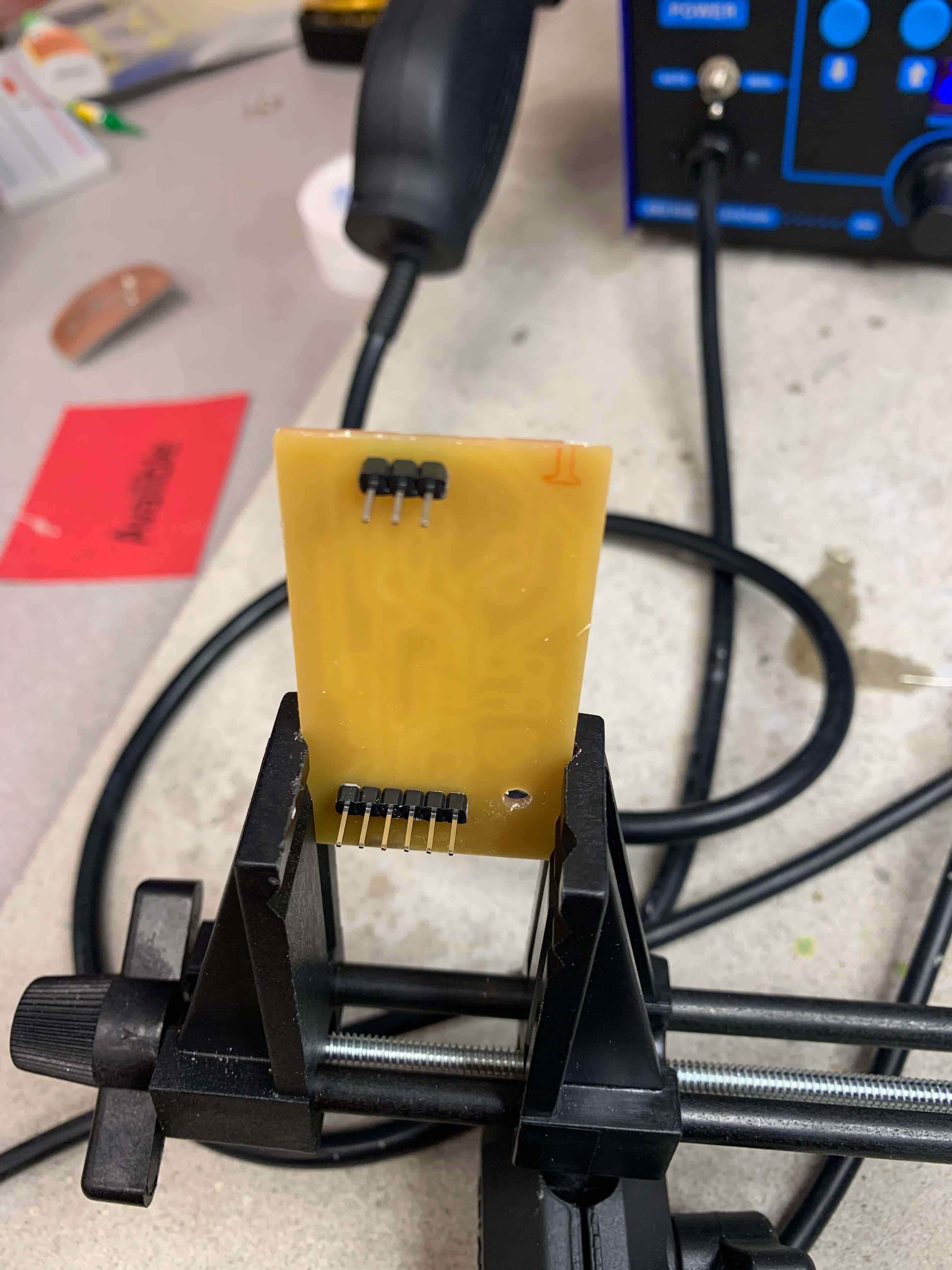
Soldering
This was another mostly easy-going process. There aren't a whole lot of parts to this board so there wasn't a lot of soldering that needed to be done. The thing that did mess me up though was solving the ATTiny 1616 just because all of the footings are so small, and there are so many of them. However, that was less of a problem more of a challenge, that I eventually overcame.
Programming
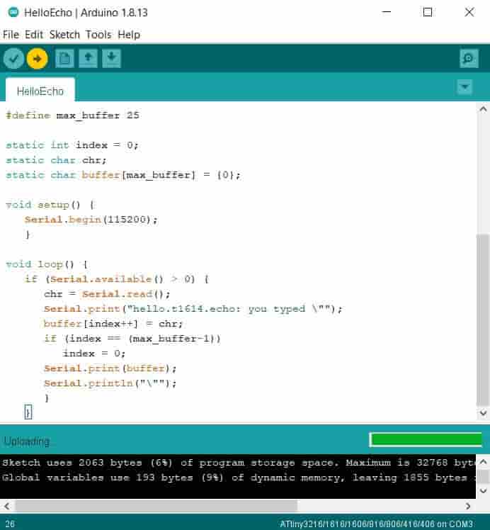
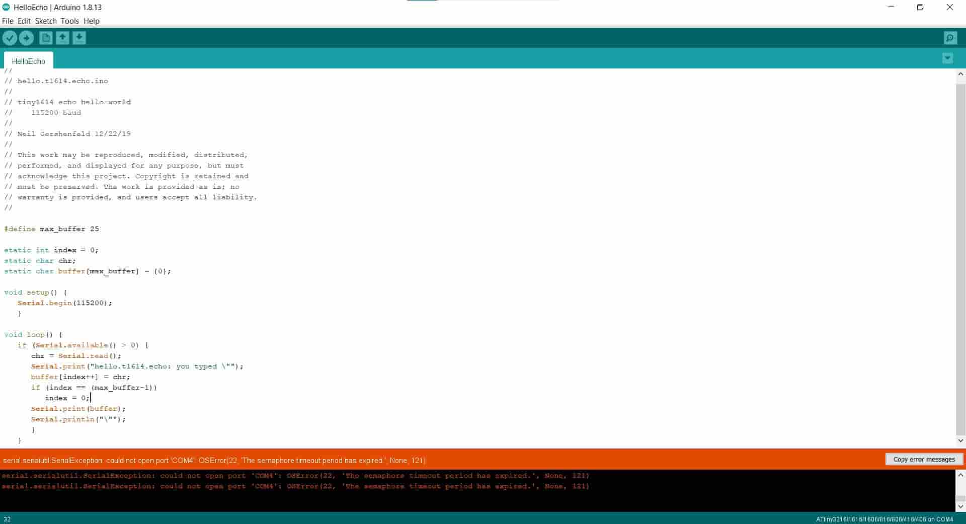
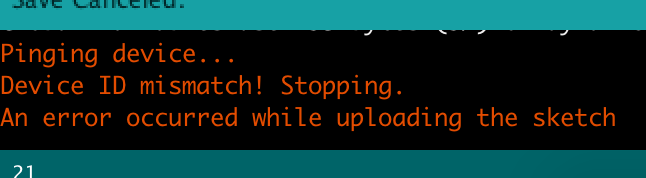
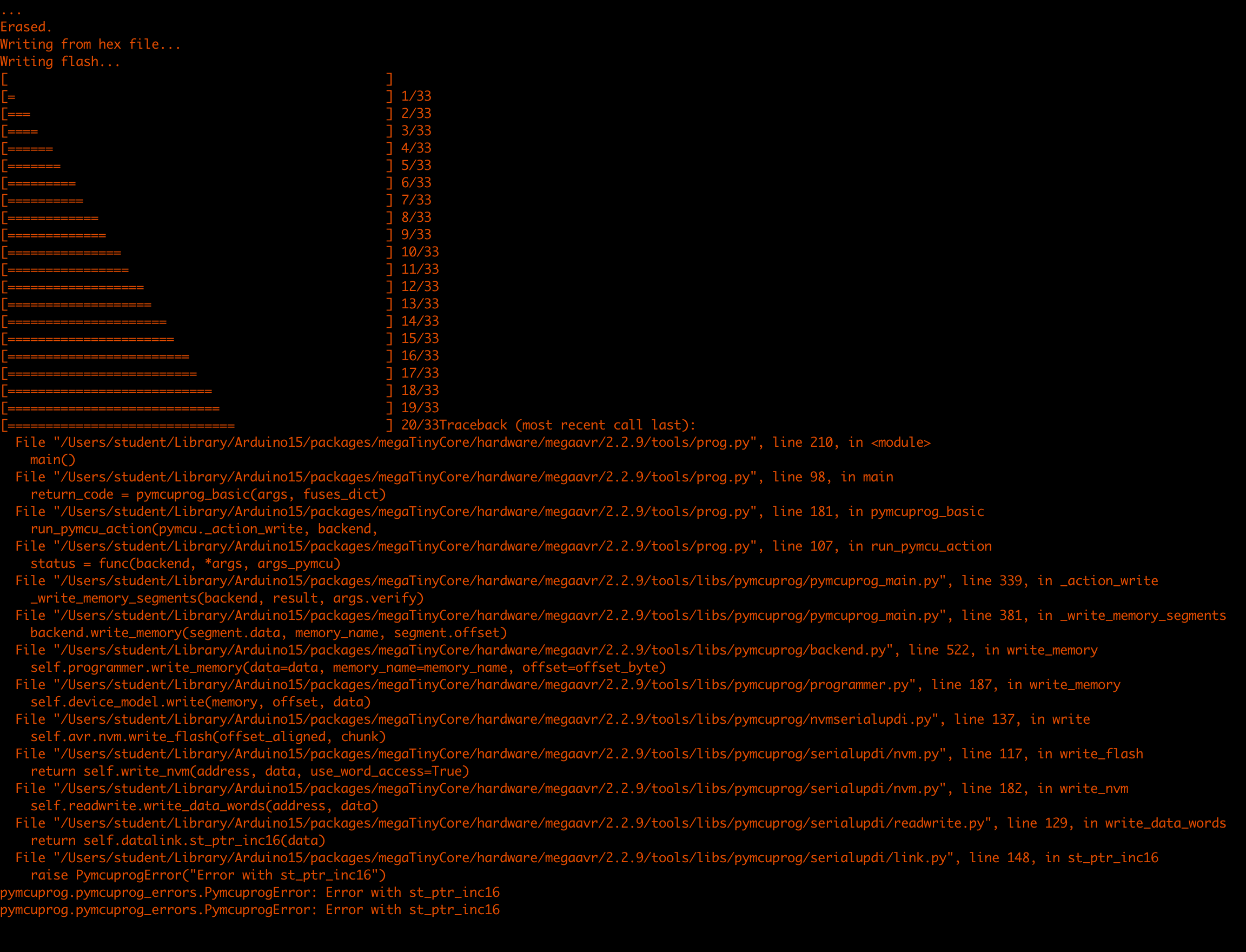
This is the part of the project where things just completely stopped going my way. To start with I should say that I'm using Arduino IDE to code my board since I've got a little bit of experience with it from an Arduino course that I took a couple of semesters ago. Arduino code is pretty much C++ so if you have any experience with that this would be great for you. Now Arduino for whatever reason doesn't recognize my USB slots, which was a darn shame, so I couldn't even try to upload the hello echo code from my laptop. I then went to one of the lab computers and went through the process of making Arduino on its able program AtTiny boards. That is mostly a process of importing the right library and making sure you have the right programming method selected. At this point, the computer told me that I had successfully programed my board. However, I couldn't type into the serial to have it write back. I thought that maybe this was just a problem with the serial monitor so I went through with the process of writing the code for LED. When I uploaded the code I got a response telling me that everything was properly uploaded. However, upon button press, nothing happened.
Potential Problems
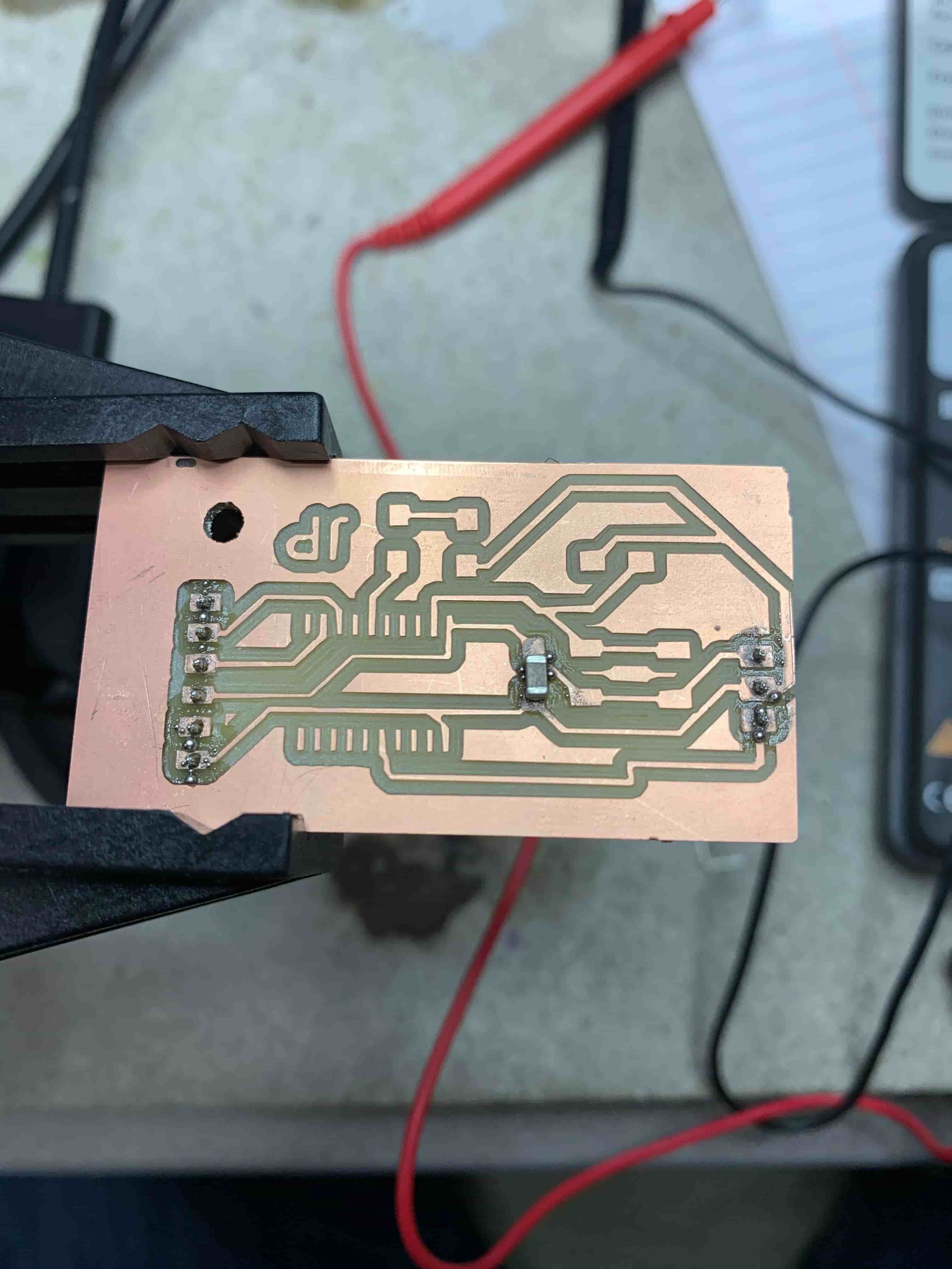
Now I know the first thought is that there is something wrong with the soldering, so that maybe something didn’t properly connect or that some traces are connected that aren't supposed to be. Those are good thoughts that I had too and I checked that very well with a multimeter, and it seemed like that was all set. The next thought in my mind is that maybe there is something wrong with the computer, however, when I program it the text says that it pings the ATTiny and it pings back so that means that must be working. All I can think is that something is fundamentally wrong with my design which is a shame, and I will add to this page once I actually can get things to work.
The solution
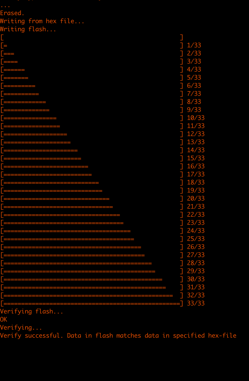
This whole process ended up having a very simple solution. I just needed to make it so that my TX and RX pins are flipped when I plug the wire into my board. I did this with some dupont wires, and it worked like a charm. I also re-sautered the pieces on just to make sure that it wasn’t a connectivity issue. Previously I said that this was a big section now that I’m writing it I don’t have a lot to say so it’s going to be on the smaller side.