Networking and Communications
Group Project
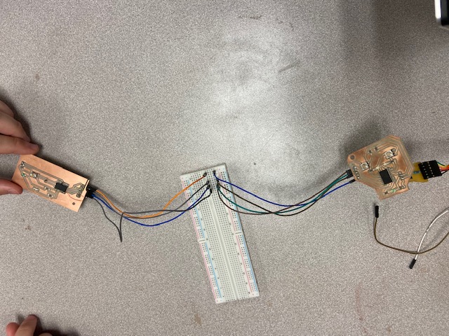
The group project this week was to make two boards from our group communicate with each other. Our group decided to replicate the game Quick Draw. The rules for Quick Draw are quite simple. Each player has a button. A light will flash at a random time, and whichever player hits their button first wins. To create this, we had one board with one LED and two buttons. We programmed the LED to turn on at random intervals. Each player would try to hit their button first. With each button press, the first board would communicate with the second board, which had two LEDs, telling it to turn on the LED assigned to the winner of the round. If you would like the code, I put the links down below.
Individual Project
My college's final exams are this week. This means that there is both good news and bad news for my Fab Academy assignments. The good news is that, after this week, I will have much more time to spend on assignments. The bad news is that I only could only carve out a small portion of time for this week's assignment. My project isn't fully working yet, but if you read this again more than five days from now, everything should be fully functional.
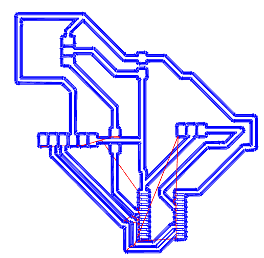
My initial plan was to tweak the board I designed at the end of last week to add a 6-pin connector to connect to an FTDI cable. I went into Kicad and updated the schema. My design has a microcontroller, a capacitor, a connector for UPDI, a connector for the output device, and another for the FTDI cable. I knew that one part would be impossible to wire, so I added a zero Ohm resistor that serves as a bridge of sorts for the electricity.
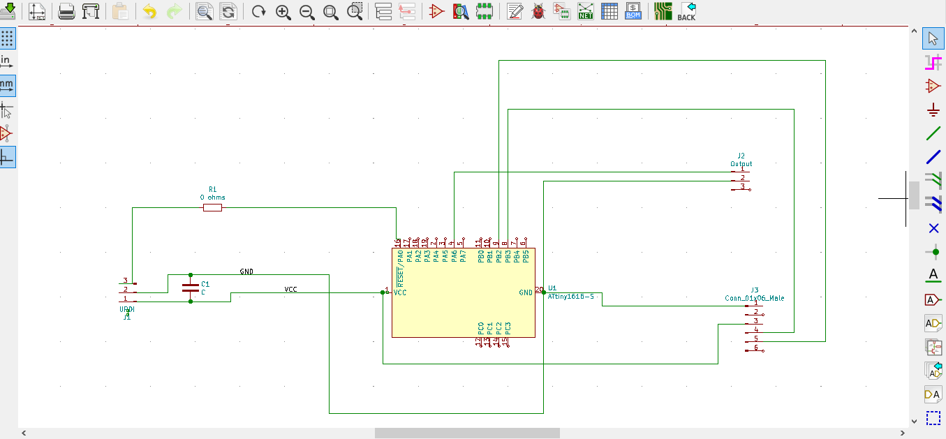
Then I Turned it into a PCB and connected everything.
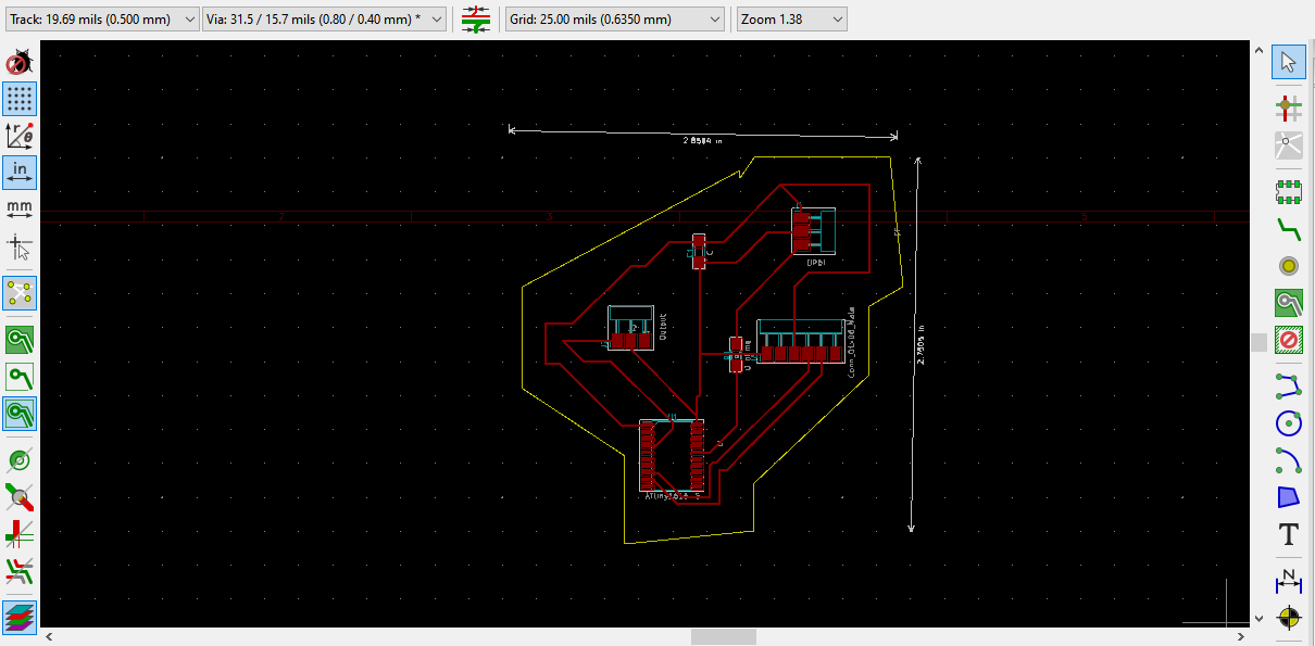
After that I went through the whole MODs process to convert it to an RML.
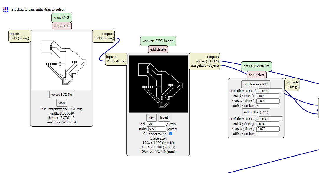
Then it was time to mill! I admittedly forgot to get pictures of this process, so I will just explain in great detail. Milling was a bit rough. The first time, I milled the board, then noticed a track I thought was connected to a pad was really just right next to the pad, and not touching. I went back and fixed that, then put everything a little bit closer to each other to use up less PCB board. When I went back to mill again, the bit was barely cutting through the board. I spent about an hour trying to remedy this. My board was secured to the bed using double stick tape, which I'm thinking made everything a bit uneven. However, I will have to ask around the lab to see if anyone else had similar problems because, if so, the bed may not be entirely level. The solution ended up being setting to Z axis to about a millimeter below where it should have been.
After that painstakingly long process was complete, I soldered all of the components onto the board.
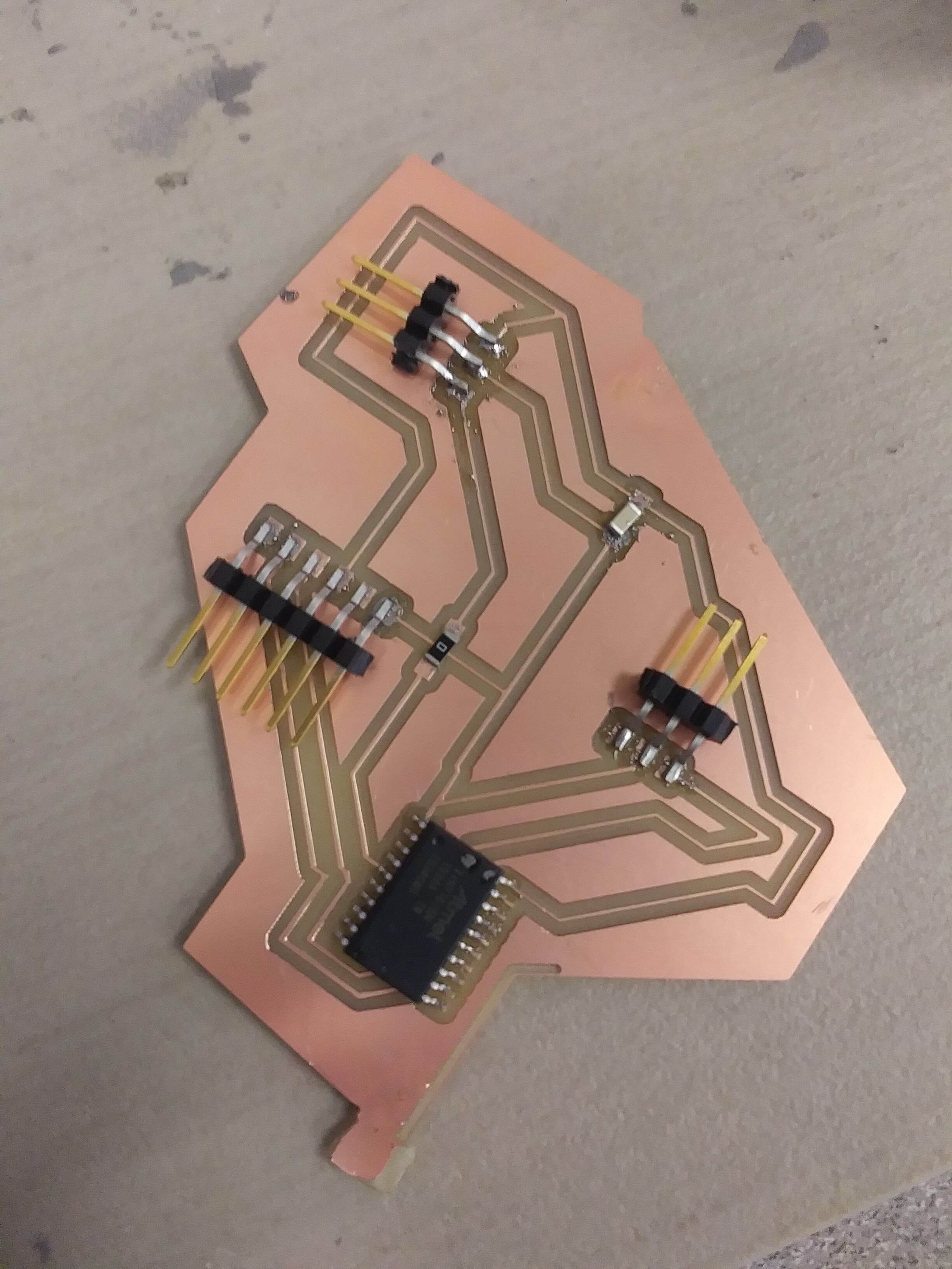
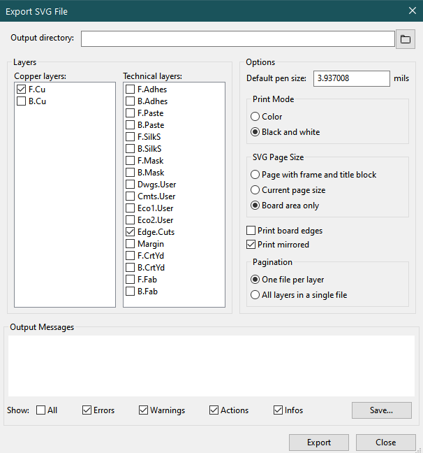
And that's when everything once again went awry. As I sat down to program the board and plugged the board into the computer, I referred to my Kicad traces to make sure I was not mixing up the Output and UPDI connectors. That's when I noticed my board was a mirror image of the trace. Appearently, I had forgotten to deselect the option to print to mirrored board before I exported the file as an SVG.
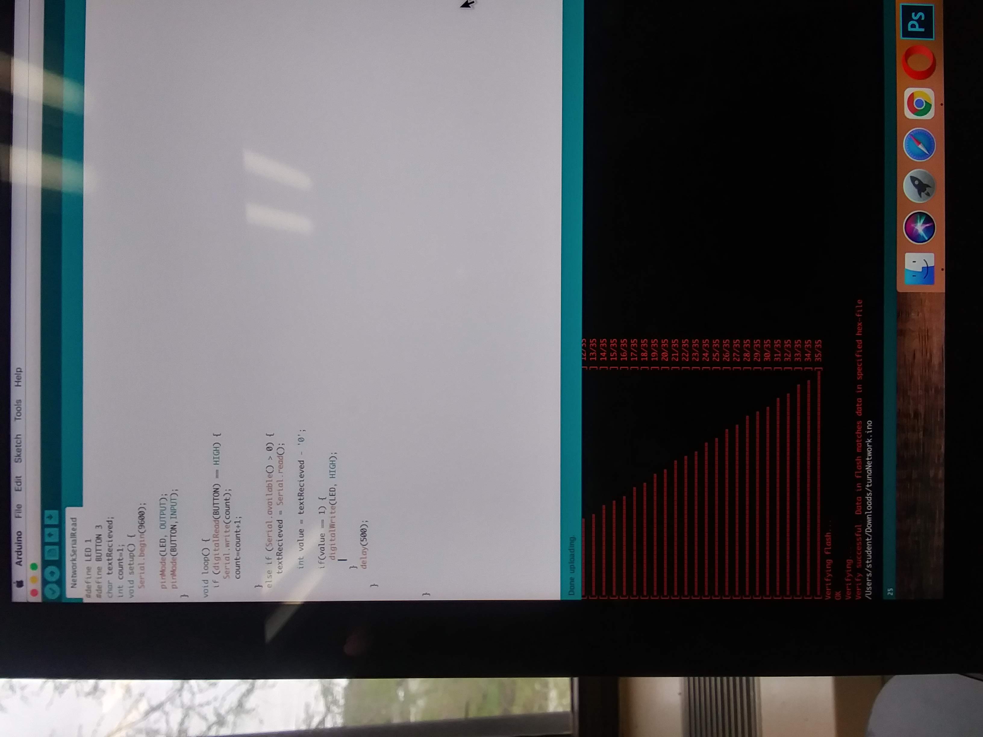
This ruined all of the connections and rendered my board unusable, which was quite unfortunate to say the least. At that point, the Machine Shop was closed, so I was not able to mill the board again. I was beginning to make plans to return to my dorm and mask my feelings of defeat with chocolate, when I realized I had a working board from Electronics Design Week. I grabbed that, then borrowed a board someone else in the lad had made to communicate with my board. They coded their board, and I coded my own. The goal was to have the button on my board be pressed, then send a value to the other board. That board would multiply the number by five, then send it back. I put my code below.
I managed to upload the code onto my board.
There unfortunately ended up being a UPDI error on the other board, so I ultimately was not able to get the board to communicate with it. On the bright side, I have 74.5 more hours until I will have completed all of my assesments and projects, and I will have the free time to mill the first design again.
Updates
Well, it's a couple of weeks later and I have finally gotten around to redoing this week. Fab Academy is basically over at this point which means A. I don't clearly remember what my prior progress on this week was and B. The board I designed for this week no longer exists (I needed the microcontrller for something else, and there is a chip shortage due to the pandemic, so I no longer have access to 1616s). So the current plan is to reprogram the working board I used in my final project and have it communicate with an Arduino Uno. If you want the files for my board design, go to
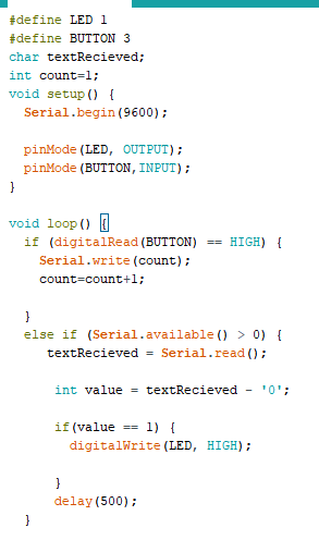
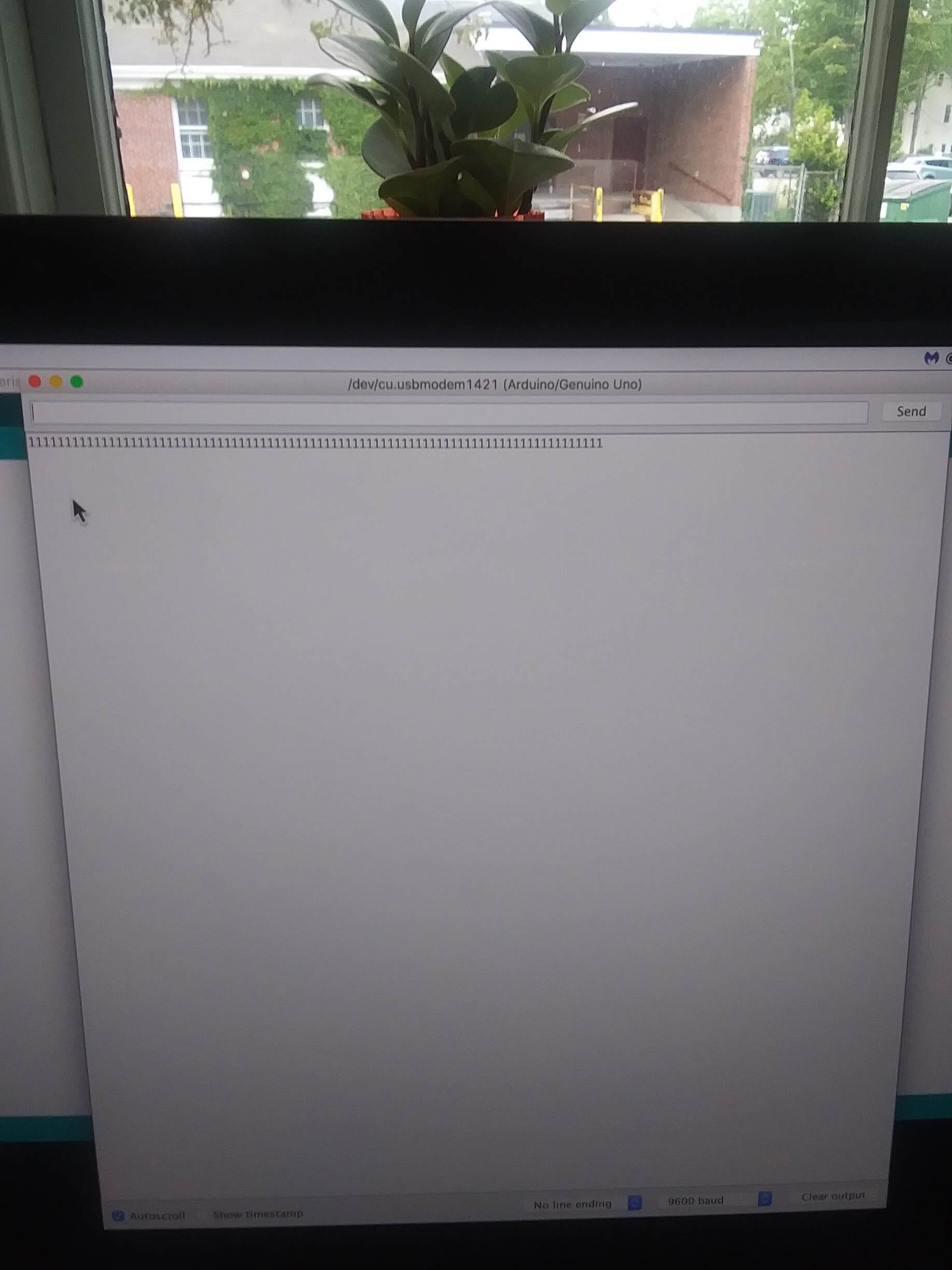
My Final Project PageI wrote two Arduino codes: one for reading and one for writing. The writing one sent the words "Hello other board" over to the other board. Much like my microcontrollers, my brain is fried, so that was the most creative thing I could come up with. I'll link to the code at theh bottom of the page. I initially wrote another code that recieved the message and would print a polite sarcastic response in the serial monitor, but didn't end up using it because when I went to program the board a few hours later, I opened the wrong code (one I had written before for something outside of this class) and found it was easier to recode parts of that than to dig through my folders to find the correct code. Typically I am not this lazy, but I was in a slight hurry and figured I could make it work. The reading code takes the input from the other code, checks to see if it is a zero, and if not prints out the count variable, which I had set to one. It will then print "1" exery half second. Retrospectively, I probably should have printed a phrase, or at least something that made a bit more sense contextually, but anyways, here is a picture of the output in Serial Monitor. And, as always, the code is linked below.
I also wrote a code that demonstrates addressing, so that if there are several boards on the same network, the two correct boards would be communicating. I had the sending code send "1A". The receiving code would then check the first character of the message it receives. If there is an "A" after the "1", it would print out "1A" into the Serial Monitor. If the first character after the 1 is not an A, than it would print an error message. I ran that code and got the below in the Serial Monitor:
.jpg)
Links
Group Project WriteGroup Project Read
Kicad Traces
Reading Code
Writing Code
Sending Code With Addressing
Receiving Code With Addressing